warning SKODA ROOMSTER 2007 1.G Repair Manual
[x] Cancel search | Manufacturer: SKODA, Model Year: 2007, Model line: ROOMSTER, Model: SKODA ROOMSTER 2007 1.GPages: 248, PDF Size: 46.44 MB
Page 76 of 248
Seats and Stowage75
Using the systemSafetyDriving TipsGeneral MaintenanceBreakdown assistancePraktikTechnical Data
Fold the armrest
– Press the lower button on the end face of the armrest ⇒page 74,
fig. 85 in order to fold the armrest. Fold the armrest forwards and
release the button.
Opening stowage compartment
– The armrest includes a stowage compartment. The storage compart-
ment is unlocked by pressing the upper button and then can be
opened to the top.
Note
The moving space of the arms can be restricted if the armrest is folded down. In city traffic the armrest should not be folded down.
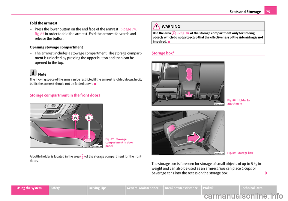
Storage compartment in the front doors
A bottle holder is located in the area of the storage compartment for the front doors.
WARNING
Use the area ⇒fig. 87 of the storage compartment only for storing objects which do not project so that the effectiveness of the side airbag is not impaired.
Storage box*
The storage box is foreseen for storage of small objects of up to 5 kg in
weight and can also be used as an armrest. You can place 2 cups or
beverage cans into the recess on the storage box.
Fig. 87 Stowage compartment in door panel
AB
AA
Fig. 88 Holder for attachment
Fig. 89 Storage box
NKO A05R 20 MR08.book Page 75 Wednesday, March 28, 2007 9:42 AM
Page 77 of 248
Seats and Stowage76
Installing storage box
– In order to create a better access to the middle seat, fold one outer
backrest forwards.
– Fold the backrest of the middle seat forwards.
– Release the fixing hook from the secured position.
– Move the fixing holder ⇒page 75, fig. 88 from the rear between the
seat cushion and seat backrest, then align the seat backrest to the
vertical position.
– Move the fixing arms of the storage box into the locking eyes of the
fixing holder until they lock in place ⇒page 75, fig. 89.
– Check the interlock of both fixing arms by pulling on the storage
box.
Removing storage box
– Simultaneously press on each side of the storage box the red button in
direction opposite the seat backrest. The storage box releases.
– Fold the seat backrest forwards and remove the fixing holder, then
move the seat backrest into the original position.
WARNING
•Do not place any hot beverages into th e cup holder. If the vehicle moves, the hot beverages may spill - risk of scalding!
•Do not use any cups or beakers which are made of brittle material (e.g. glass, porcelain). You might be injured by them in the event of an accident.
•While driving, the storage box can only be used as an armrest in its closed position.
Caution
Do not open the beverages in the cup holder while driving. There is a risk of spilling e.g. when braking and therefore the electrical components or the seat upholstery can be damaged.
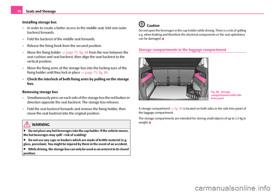
Storage compartments in the luggage compartment
A storage compartment ⇒fig. 90 is located on both sides in the side trim panel of the luggage compartment.
The storage compartments are intended for storing small objects of up to 1.5 kg in weight.
Fig. 90 Storage compartments in the side trim panel
NKO A05R 20 MR08.book Page 76 Wednesday, March 28, 2007 9:42 AM
Page 78 of 248
Seats and Stowage77
Using the systemSafetyDriving TipsGeneral MaintenanceBreakdown assistancePraktikTechnical Data
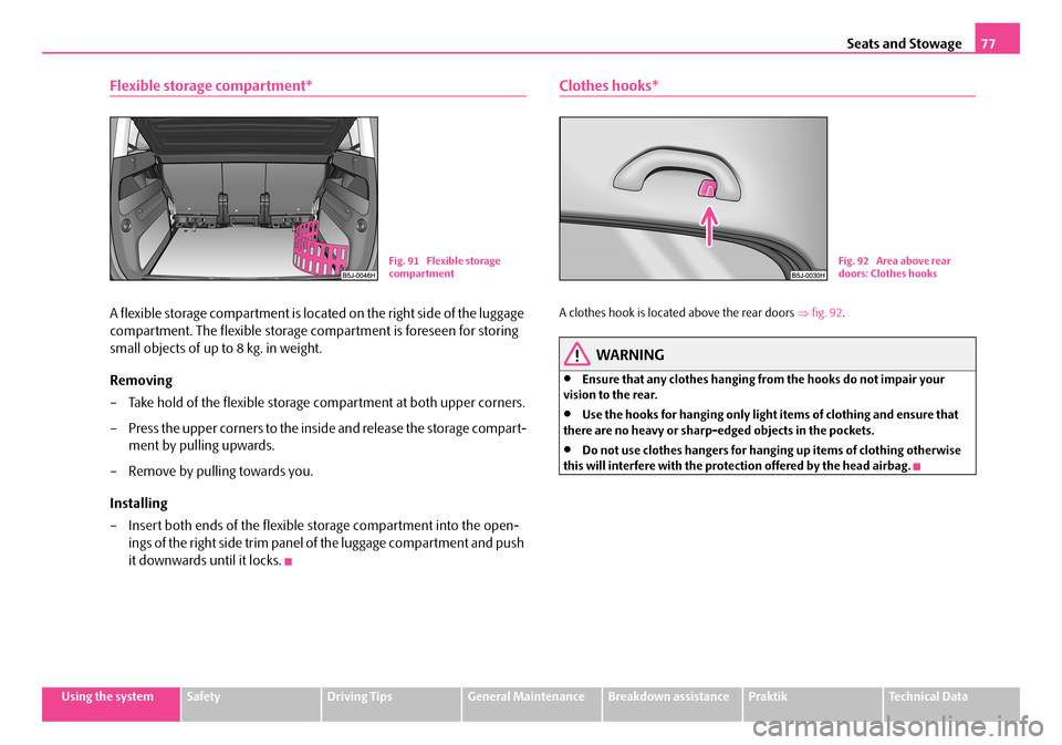
Flexible storage compartment*
A flexible storage compartment is located on the right side of the luggage
compartment. The flexible storage compartment is foreseen for storing
small objects of up to 8 kg. in weight.
Removing
– Take hold of the flexible storage compartment at both upper corners.
– Press the upper corners to the inside and release the storage compart-
ment by pulling upwards.
– Remove by pulling towards you.
Installing
– Insert both ends of the flexible storage compartment into the open-
ings of the right side trim panel of the luggage compartment and push
it downwards until it locks.
Clothes hooks*
A clothes hook is located above the rear doors ⇒fig. 92.
WARNING
•Ensure that any clothes hanging from the hooks do not impair your vision to the rear.
•Use the hooks for hanging only light items of clothing and ensure that there are no heavy or sharp-e dged objects in the pockets.
•Do not use clothes hangers for hanging up items of clothing otherwise this will interfere with the protection offered by the head airbag.
Fig. 91 Flexible storage compartmentFig. 92 Area above rear doors: Clothes hooks
NKO A05R 20 MR08.book Page 77 Wednesday, March 28, 2007 9:42 AM
Page 79 of 248
Heating and air conditioning system78
Heating and air conditioning system
Heating
Using the system
The heating system delivers air into the interior of the vehicle and
warms it as required.
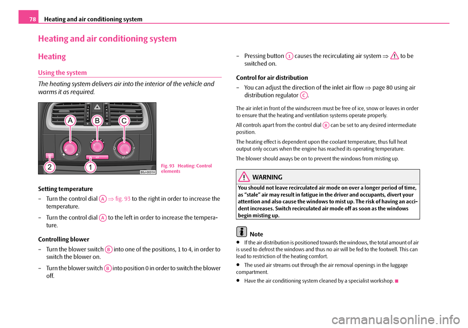
Setting temperature
– Turn the control dial ⇒fig. 93 to the right in order to increase the
temperature.
– Turn the control dial to the left in order to increase the tempera-
ture.
Controlling blower
– Turn the blower switch into one of the positions, 1 to 4, in order to
switch the blower on.
– Turn the blower switch into position 0 in order to switch the blower
off.
– Pressing button causes the recirculating air system ⇒ to be
switched on.
Control for air distribution
– You can adjust the direction of the inlet air flow ⇒page 80 using air
distribution regulator .
The air inlet in front of the windscreen must be free of ice, snow or leaves in order to ensure that the heating and ventilation systems operate properly.
All controls apart from the control dial can be set to any desired intermediate position.
The heating effect is dependent upon th e coolant temperature, thus full heat output only occurs when the engine has reached its operating temperature.
The blower should aways be on to prevent the windows from misting up.
WARNING
You should not leave recirculated air mode on over a longer period of time, as “stale” air may result in fatigue in the driver and occupants, divert your attention and also cause the windows to mist up. The risk of having an acci- dent increases. Switch recirculated air mode off as soon as the windows begin misting up.
Note
•If the air distribution is positioned towa rds the windows, the total amount of air is used to defrost the window s and thus no air will be fed to the footwell. This can lead to restriction of the heating comfort.
•The used air streams out through the air removal openings in the luggage compartment.
•Have the air conditioning system cleaned by a specialist workshop.
Fig. 93 Heating: Control elements
AA
AA
AB
AB
A1
AC
AB
NKO A05R 20 MR08.book Page 78 Wednesday, March 28, 2007 9:42 AM
Page 81 of 248
Heating and air conditioning system80
WARNING
You should not leave recirculated air mode on over a longer period of time, as “stale” air may result in fatigue in the driver and occupants, divert your attention and also cause the windows to mist up. The risk of having an acci- dent increases. Switch recirculated air mode off as soon as the windows begin misting up.
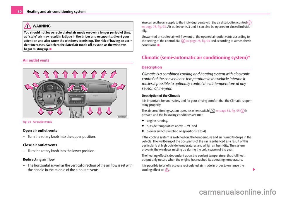
Air outlet vents
Fig. 94 Air outlet vents
Open air outlet vents
– Turn the rotary knob into the upper position.
Close air outlet vents
– Turn the rotary knob into the lower position.
Redirecting air flow
– The horizontal as well as the vertical direction of the air flow is set with
the handle in the middle of the air outlet vents.
You can set the air supply to the individual vents with the air distribution control ⇒ page 78, fig. 93. Air outlet vents 3 and 4 can also be opened or closed individu- ally.
Unwarmed or cooled air will flow out of the opened air outlet vents according to the setting of the control dial ⇒page 78, fig. 93 and according to atmospheric conditions.
Climatic (semi-automatic air conditioning system)*
Description
Climatic is a combined cooling an d heating system with electronic
control of the convenience temperat ure in the vehicle interior. It
makes it possible to optimally co ntrol the air temperature at any
season of the year.
Description of the Climatic
It is important for your safety and for your driving comfort that the Climatic is oper- ating properly.
The air conditioning system operates when switch ⇒page 81, fig. 95 is pressed and the following conditions are met:
•engine running,
•outside temperature above +2°C and
•blower switch switched on (positions 1 to 4).
If the cooling system is switched on, the temperature and air humidity drops in the vehicle. The wellbeing of the occupants of the car is enhanced as a result of this particularly at high outside temperatures and a high air humidity. The system prevents the windows misting up during the cold season of the year.
The heating effect is dependent upon th e coolant temperature, thus full heat output only occurs when the engine has reached its operating temperature.
It is possible to briefly activate recirculated air mode in order to enhance the cooling effect ⇒.
AC
AA
ACAE
NKO A05R 20 MR08.book Page 80 Wednesday, March 28, 2007 9:42 AM
Page 82 of 248
Heating and air conditioning system81
Using the systemSafetyDriving TipsGeneral MaintenanceBreakdown assistancePraktikTechnical Data
Air at a temperature of about 5°C may flow out of the vents under certain circum- stances when the cooling system is operating. Lengthy and uneven distribution of the air flow out of the vents (in particular at the leg area) and large differences in temperature, for example when getting out of the vehicle, can result in chills in sensitive persons.
The air inlet in front of the windscreen must be free of ice, snow or leaves in order to ensure that the heating and cooling systems operate properly.
After switching on the cooling Condensation from the evaporator of the air condi- tioning may drip down and form a puddle below the vehicle. This is quite normal and not an indication of a leak!
WARNING
•For your own safety and that of other road users, ensure that all the windows are free of ice, snow and mistin g. Please familiarize yourself about how to correctly operate th e heating and ventilation systems, how to demist and defrost the windows, as well as with the cooling mode.
•You should not leave recirculated air mode on over a longer period of time, as “stale” air may result in fatigue in the driver and occupants, divert your attention and also cause the windows to mist up. The risk of having an accident increases. Switch recirculated air mode off as soon as the windows begin misting up.
Note
•We recommend that you do not smoke in the vehicle when the recirculating air mode is operating since the smoke which is drawn at the evaporator from the inte- rior of the vehicle forms deposits in the evaporator of the air conditioning system. This produces a permanent odour when the Climatic is operating which can only be eliminated through considerable effort and expense (replacement of compressor).
Using the system
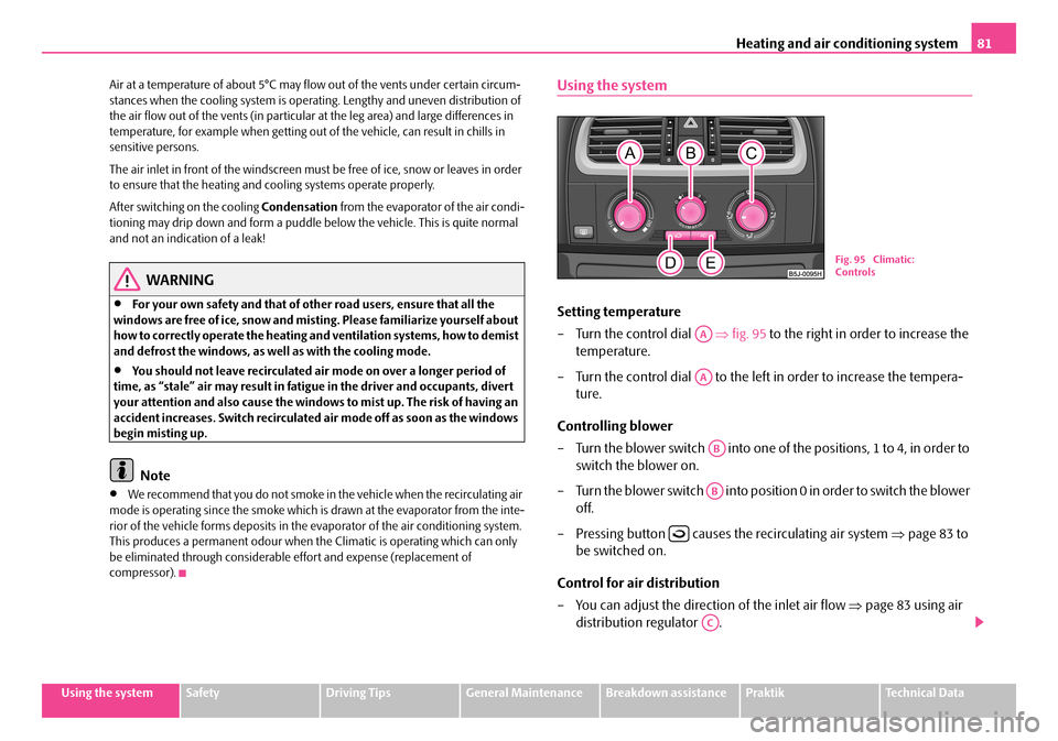
Setting temperature
– Turn the control dial ⇒fig. 95 to the right in order to increase the
temperature.
– Turn the control dial to the left in order to increase the tempera-
ture.
Controlling blower
– Turn the blower switch into one of the positions, 1 to 4, in order to
switch the blower on.
– Turn the blower switch into position 0 in order to switch the blower
off.
– Pressing button causes the recirculating air system ⇒page 83 to
be switched on.
Control for air distribution
– You can adjust the direction of the inlet air flow ⇒page 83 using air
distribution regulator .
Fig. 95 Climatic: Controls
AA
AA
AB
AB
AC
NKO A05R 20 MR08.book Page 81 Wednesday, March 28, 2007 9:42 AM
Page 84 of 248
Heating and air conditioning system83
Using the systemSafetyDriving TipsGeneral MaintenanceBreakdown assistancePraktikTechnical Data
Cooling down the inside of the vehicle as rapidly as possible
•close all windows
•Control dial at the desired heat temperature
•Blower switch in position 4
•Turn the air distribution control into the position
•Open the air outlet vents 3 and 4
•Switch on the cooling system by pressing button
•We recommend that you briefly switch on the recirculated air mode with the pushbutton .
Optimum cooling
•Control dial at the desired heat temperature. This temperature will be main- tained automatically.
•Blower switch in position 1, 2 or 3
•Turn the air distribution control into the position
•Open the air outlet vents 3 and 4
•Switch on the cooling system by pressing button
•We recommend setting the air outlet vents 3 and 4 in such a way that the air flows to the rear over the heads of the occu pants. Do not switch to recirculated air mode.
Recirculated air mode
In recirculated air mode air is sucked out of the interior of the vehicle
and then fed back into the interior.
Recirculated air mode prevents polluted air outside the vehicle from
getting into the vehicle, for example when driving through a tunnel or
when standing in a traffic jam.
Switching recirculated air mode on
– Press switch ⇒page 81, fig. 95 the switch symbol lights up.
Switching recirculated air mode off
– Press button again, the button symbol goes out.
The recirculated air mode is switched off au tomatically if the air distribution control is in position ⇒page 81, fig. 95. You can also switch recirculated air mode on again from this setting by repeatedly pressing button .
WARNING
You should not leave recirculated air mode on over a longer period of time, as “stale” air may result in fatigue in the driver and occupants, divert your attention and also cause the windows to mist up. The risk of having an acci-dent increases. Switch recirculated air mode off as soon as the windows begin misting up.
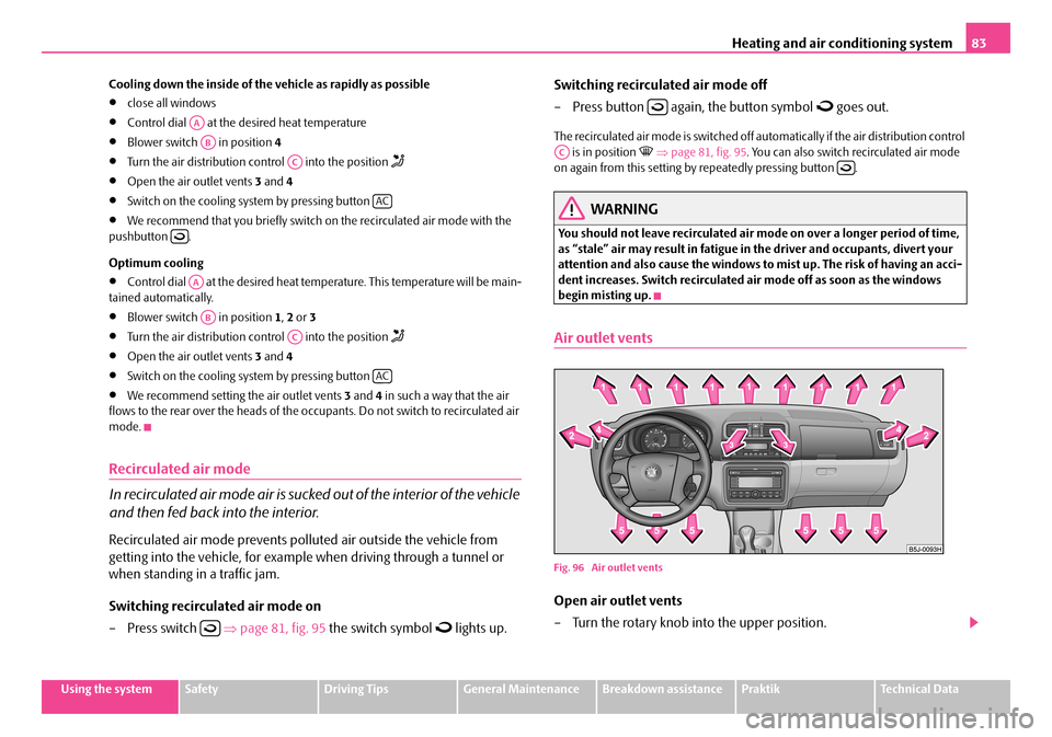
Air outlet vents
Fig. 96 Air outlet vents
Open air outlet vents
– Turn the rotary knob into the upper position.
AA
AB
AC
AC
AA
AB
AC
AC
AC
NKO A05R 20 MR08.book Page 83 Wednesday, March 28, 2007 9:42 AM
Page 86 of 248
Heating and air conditioning system85
Using the systemSafetyDriving TipsGeneral MaintenanceBreakdown assistancePraktikTechnical Data
The heating effect is dependent upon th e coolant temperature, thus full heat output only occurs when the engine has reached its operating temperature.
It is possible to briefly activate recirc ulated air mode in order to enhance the cooling effect ⇒.
The air inlet in front of the windscreen must be free of ice, snow or leaves in order to ensure that the heating and cooling systems operate properly.
The AC compressor is switched off at a hi gh coolant temperature in order to provide cooling at a high load of the engine.
After switching on the cooling Condensation from the evaporator of the air condi- tioning may drip down and form a puddle below the vehicle. This is quite normal and not an indication of a leak!
Recommended setting for al l periods of the year:
•Set the temperature to 22 °C.
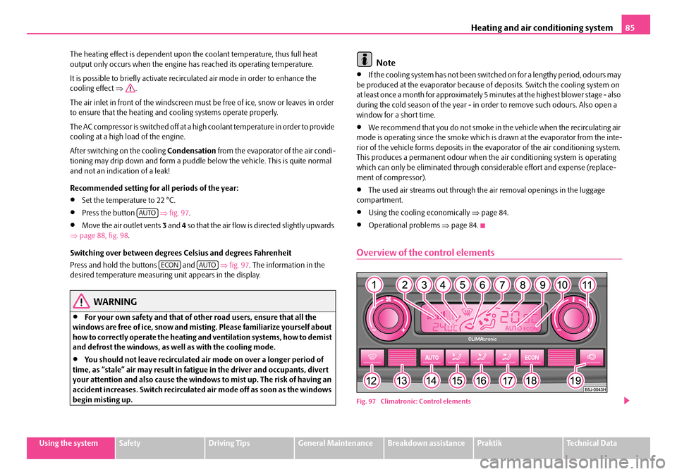
•Press the button ⇒fig. 97.
•Move the air outlet vents 3 and 4 so that the air flow is directed slightly upwards ⇒ page 88, fig. 98.
Switching over between degrees Celsius and degrees Fahrenheit
Press and hold the buttons and ⇒fig. 97. The information in the desired temperature measuring unit appears in the display.
WARNING
•For your own safety and that of other road users, ensure that all the windows are free of ice, snow and mistin g. Please familiarize yourself about how to correctly operate th e heating and ventilation systems, how to demist and defrost the windows, as well as with the cooling mode.
•You should not leave recirculated air mode on over a longer period of time, as “stale” air may result in fatigue in the driver and occupants, divert your attention and also cause the windows to mist up. The risk of having an accident increases. Switch recirculated air mode off as soon as the windows begin misting up.
Note
•If the cooling system has not been switched on for a lengthy period, odours may be produced at the evaporator because of deposits. Switch the cooling system on at least once a month for approximately 5 mi nutes at the highest blower stage - also during the cold season of the year - in order to remove such odours. Also open a window for a short time.
•We recommend that you do not smoke in the vehicle when the recirculating air mode is operating since the smoke which is drawn at the evaporator from the inte- rior of the vehicle forms deposits in the ev aporator of the air conditioning system. This produces a permanent odour when th e air conditioning system is operating which can only be eliminated through co nsiderable effort and expense (replace- ment of compressor).
•The used air streams out through the air removal openings in the luggage compartment.
•Using the cooling economically ⇒page 84.
•Operational problems ⇒page 84.
Overview of the control elements
Fig. 97 Climatronic: Control elements
AUTO
ECONAUTO
NKO A05R 20 MR08.book Page 85 Wednesday, March 28, 2007 9:42 AM
Page 88 of 248
Heating and air conditioning system87
Using the systemSafetyDriving TipsGeneral MaintenanceBreakdown assistancePraktikTechnical Data
Please refer to the information regarding recirculated air mode ⇒page 87.
Defrosting windscreen
Defrosting windscreen - switching on
– Press the button ⇒page 85, fig. 97.
Defrosting windscreen - switching off
– Once again press the button or the button .
The temperature control is controlled automa tically. More air flows out of the air outlet vents 1 and2.
Recirculated air mode
In recirculated air mode air is sucked out of the interior of the vehicle
and then fed back into the interior.
Recirculated air mode prevents polluted air outside the vehicle from
getting into the vehicle, for example when driving through a tunnel or
when standing in a traffic jam.
Switching recirculated air mode on
– Press button , the symbol appears on the display.
Switching recirculated air mode off
– Once again press the button or the button , the symbol or
the logo is no longer shown on the display.
WARNING
•You should not leave recirculated air mode on over a longer period of time, as “stale” air may result in fatigue in the driver and occupants, divert your attention and also cause the windows to mist up. The risk of having an
accident increases. Switch recirculated air mode off as soon as the windows begin misting up.
•After 15 minutes of constant recirculated air mode, the symbol flashes on the display of the Climatro nic for 5 minutes. Immediately switch off the recirculated air mode.
Note
If the windscreen mists up, press the button . After the windscreen has been demisted, press the button .
Setting temperature
– You can set the desired interior temperature after switching on the
ignition with the control dial .
You can set the interior temperature be tween +18°C and +29°C. The interior temperature is regulated automatically with in this range. If you select a tempera- ture of less than +18 °C, “LO” is shown on the display. If you select a temperature above +29 °C, “HI” is shown on the displa y. In both limit positions the Climatronic operates at maximum cooling or heating capacity, respectively. The temperature is not controlled in this case.
Lengthy and uneven distribution of the air flow out of the vents (in particular at the leg area) and large differences in temperat ure, for example when getting out of the vehicle, can result in chills in sensitive persons.
Controlling blower
There are a total of seven blower stages available.
The Climatronic system controls the bl ower stages automatically in line
with the interior temperature. You can also, however, adapt the blower
stages manually to suit your particular needs.
AUTO
AUTO
WARNING (continued)
AUTO
A11
NKO A05R 20 MR08.book Page 87 Wednesday, March 28, 2007 9:42 AM
Page 89 of 248
Heating and air conditioning system88
– Turn the control dial ⇒page 85, fig. 97 to the left (reduce blower
speed) or right (increase blower speed).
Switch off the blowers, the Climatronic is switched off and in the display shows OFF.
The set blower speed is displayed next to the control dial when the respective number of warning lights come on.
WARNING
•“Stale air” may result in fatigue in the driver and occupants, reduce attention levels and also cause the windows to mist up. The risk of having an accident increases.
•Do not switch the Climatronic system off for longer than necessary.
•Switch the Climatronic system on as soon as the windows mist up.
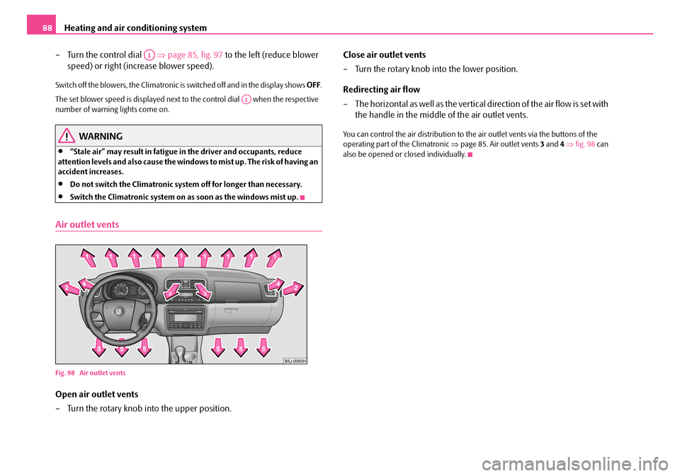
Air outlet vents
Fig. 98 Air outlet vents
Open air outlet vents
– Turn the rotary knob into the upper position.
Close air outlet vents
– Turn the rotary knob into the lower position.
Redirecting air flow
– The horizontal as well as the vertical direction of the air flow is set with
the handle in the middle of the air outlet vents.
You can control the air distribution to the air outlet vents via the buttons of the operating part of the Climatronic ⇒page 85. Air outlet vents 3 and 4 ⇒fig. 98 can also be opened or closed individually.
A1
A1
NKO A05R 20 MR08.book Page 88 Wednesday, March 28, 2007 9:42 AM