technical data SKODA ROOMSTER 2008 1.G Owner's Guide
[x] Cancel search | Manufacturer: SKODA, Model Year: 2008, Model line: ROOMSTER, Model: SKODA ROOMSTER 2008 1.GPages: 248, PDF Size: 46.44 MB
Page 46 of 248
Lights and Visibility45
Using the systemSafetyDriving TipsGeneral MaintenanceBreakdown assistancePraktikTechnical Data
WARNING
Never drive with side lights on - risk of accident! The side lights are not bright enough to light up the road sufficiently in front of you or to be seen by other oncoming traffic. In this case, always switch on the low beam when it is dark or if visibility is poor.
Note
•An audible warning will sound if you wi thdraw the ignition key and open the driver's door when the vehicle lights are still on.
•The acoustic warning signal is switched off over the door contact when the driver's door is closed (ignition off). The vehicle can be parked with the side lights on.
•If you park the car for a lengthy period , we recommend switching off all lights, or leaving only the side lights switched on.
•The switching on of the described lights should only be undertaken in accord- ance with the legal requirements.
•In the event of cool or humid weather co nditions, the headlights can be misted up from inside.
− The temperature difference between interior and external area of the head- light lenses is decisive.
− When the driving lights are switched on, the light outlet surfaces are free from mist after a short period. The headlight lenses can possibly mist up at the border areas.
− It also concerns reverse light and turn signal lights.
− This mist has no influence on the life of the lighting system.
Cornering lights*
For a better cornering illumination the cornering lights are controlled in the optimal position in line with the vehi cle speed and the steering angle.
If the warning light flashes for 1 minute while driving or after switching on the ignition and a warning signal sounds, a fault is confirmed.
WARNING
If there is a fault in the cornering lights, the warning light flashes in the instrument cluster. The cornering li ghts are automatically lowered to the emergency position, which prevents a po ssible dazzling of oncoming traffic. Thus the illuminated length of the road is shortened. Drive carefully and have the car inspected immedi ately by a specialist garage.
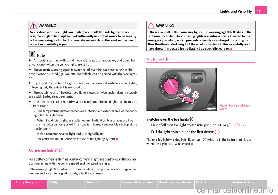
Fog lights*
Switching on the fog lights
– First of all turn the light switch into position or ⇒fig. 33.
– Pull the light switch out to the first detent .
The rear fog light warning light ⇒page 20 lights up in the instrument cluster when the fog light is switched off.
Fig. 33 Dash panel: Light switch
A1
NKO A05R 20 MR08.book Page 45 Wednesday, March 28, 2007 9:42 AM
Page 48 of 248
Lights and Visibility47
Using the systemSafetyDriving TipsGeneral MaintenanceBreakdown assistancePraktikTechnical Data
Caution
Set the headlight beam adjustment in such a way as to avoid dazzling oncoming traffic.
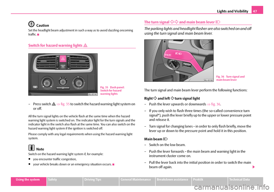
Switch for hazard warning lights
– Press switch ⇒fig. 35 to switch the hazard warning light system on
or off.
All the turn signal lights on the vehicle flash at the same time when the hazard warning light system is switched on. The in dicator light for the turn signals and the indicator light in the switch also flash at the same time. You can also switch on the hazard warning light system if the ignition is switched off.
Please comply with any legal requirements when using the hazard warning light system.
Note
Switch on the hazard warning light system if, for example:
•you encounter traffic congestion,
•your vehicle breaks down or an emergency situation occurs.
The turn signal and main beam lever
The parking lights and headlight flasher are also switched on and off
using the turn signal and main beam lever.
The turn signal and main beam le ver perform the following functions:
Right and left turn signal light
– Push the lever upwards or downwards ⇒fig. 36.
– If you only wish to flash three ti mes (the so-called convenience turn
signal*), push the lever briefly up to the upper or lower pressure point
and release it.
– Turn signal for changing lanes - in order to only flash briefly, move the
lever up or down to the pressure po int and hold it in this position.
Main beam
– Switch on the low beam.
– Push the lever forwards - the main beam and warning light in the
instrument cluster come on.
– Pull the lever back into the initial position in order to switch the main
beam off again.
Fig. 35 Dash panel: Switch for hazard warning lights
Fig. 36 Turn signal and main beam lever
NKO A05R 20 MR08.book Page 47 Wednesday, March 28, 2007 9:42 AM
Page 50 of 248
Lights and Visibility49
Using the systemSafetyDriving TipsGeneral MaintenanceBreakdown assistancePraktikTechnical Data
Lighting of storage compartment on the front passenger side
– When opening the flap of the storage compartment on the front
passenger side the lighting in the storage compartment comes on.
– The light switches on automatically when the parking light is switched
on and goes out when the flap is closed.
The interior light is switched on for abou t 20 seconds when a vehicle with a central locking system is unlocked, when a door is opened or when the ignition key is removed. The requirement for this is that the switch is in the door contact position. The inner light goes out out immediately after the ignition is switched on.
A time delay switch* causes the inner lighti ng on vehicles without a central locking system stays on for a few seconds after the doors have been closed. The inner light goes out out immediately after the ignition is switched on.
The interior lighting is switched off af ter about 30 minutes when a door has been left open in order to avoid discharging the battery of the vehicle.
Rear interior lighting*
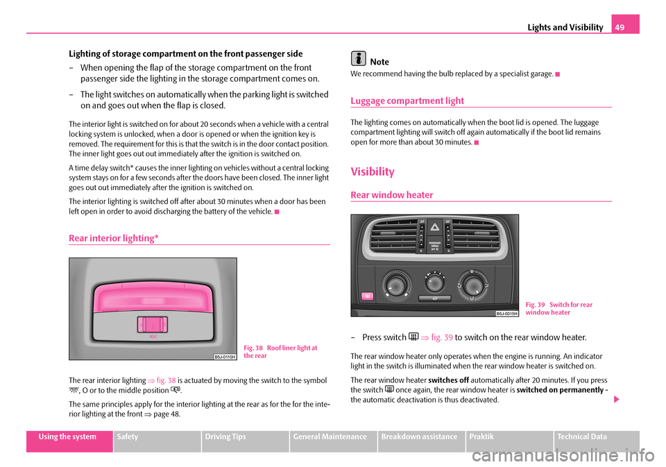
The rear interior lighting ⇒fig. 38 is actuated by moving the switch to the symbol , O or to the middle position .
The same principles apply for the interior lighting at the rear as for the for the inte- rior lighting at the front ⇒page 48.
Note
We recommend having the bulb replaced by a specialist garage.
Luggage compartment light
The lighting comes on automatically when the boot lid is opened. The luggage compartment lighting will switch off again automatically if the boot lid remains open for more than about 30 minutes.
Visibility
Rear window heater
– Press switch ⇒fig. 39 to switch on the rear window heater.
The rear window heater only operates when the engine is running. An indicator light in the switch is illuminated when the rear window heater is switched on.
The rear window heater switches off automatically after 20 minutes. If you press the switch once again, the rear window heater is switched on permanently - the automatic deactivation is thus deactivated.
Fig. 38 Roof liner light at the rear
Fig. 39 Switch for rear window heater
NKO A05R 20 MR08.book Page 49 Wednesday, March 28, 2007 9:42 AM
Page 52 of 248
Lights and Visibility51
Using the systemSafetyDriving TipsGeneral MaintenanceBreakdown assistancePraktikTechnical Data
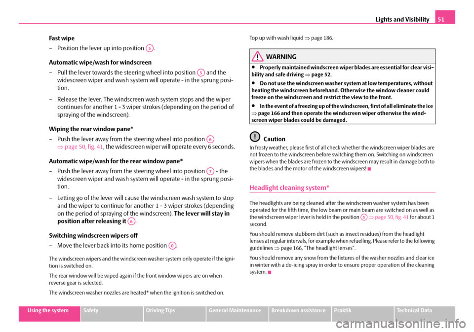
Fast wipe
– Position the lever up into position .
Automatic wipe/wash for windscreen
– Pull the lever towards the steering wheel into position and the
widescreen wiper and wash system wi ll operate - in the sprung posi-
tion.
– Release the lever. The windscreen wash system stops and the wiper
continues for another 1 - 3 wiper stro kes (depending on the period of
spraying of the windscreen).
Wiping the rear window pane*
– Push the lever away from the steering wheel into position
⇒ page 50, fig. 41, the widescreen wiper will operate every 6 seconds.
Automatic wipe/wash for the rear window pane*
– Push the lever away from the steering wheel into position - the
widescreen wiper and wash system wi ll operate - in the sprung posi-
tion.
– Letting go of the lever will cause the windscreen wash system to stop
and the wiper to continue for another 1 - 3 wiper strokes (depending
on the period of spraying of the windscreen). The lever will stay in
position after releasing it .
Switching windscreen wipers off
– Move the lever back into its home position .
The windscreen wipers and the windscreen washer system only operate if the igni- tion is switched on.
The rear window will be wiped again if the front window wipers are on when reverse gear is selected.
The windscreen washer nozzles are heated* when the ignition is switched on.
Top up with wash liquid ⇒page 186.
WARNING
•Properly maintained windscreen wiper blades are essential for clear visi- bility and safe driving ⇒page 52.
•Do not use the windscreen washer system at low temperatures, without heating the windscreen beforehand. Otherwise the window cleaner could freeze on the windscreen and restrict the view to the front.
•In the event of a freezing up of the wi ndscreen, first of all eliminate the ice ⇒ page 166 and then operate the windscreen wiper otherwise the wind- screen wiper blades could be damaged.
Caution
In frosty weather, please first of all check whether the windscreen wiper blades are not frozen to the windscreen before switching them on. Switching on windscreen wipers when the blades are frozen to the windscreen may result in damage both to the blades and the motor of the windscreen wipers!
Headlight cleaning system*
The headlights are being cleaned after the windscreen washer system has been operated for the fifth time, the low beam or main beam are switched on as well as the windscreen wiper lever is held in the position ⇒page 50, fig. 41 for about 1 second.
You should remove stubborn dirt (such as insect residues) from the headlight lenses at regular intervals, for example when refuelling. Please refer to the following guidelines ⇒page 166, “The headlight lenses”.
You should remove any snow from the fixtures of the washer nozzles and clear ice in winter with a de-icing spray in order to ensure proper operation of the cleaning system.
A3
A5
A6
A7
A6
A0
A5
NKO A05R 20 MR08.book Page 51 Wednesday, March 28, 2007 9:42 AM
Page 54 of 248
Lights and Visibility53
Using the systemSafetyDriving TipsGeneral MaintenanceBreakdown assistancePraktikTechnical Data
Attaching a wiper blade
– Position the wiper blade onto th e wiper arm and lock the locking
button .
– Check whether the wiper blade is correctly attached.
The same remarks apply here as for ⇒page 52.
Rear mirror
You can adjust the exterior mirrors electrically*.
Adjust the rear mirror before commencing to drive so that there is a clear
view to the rear.
Dimming the interior mirror
– Pull the lever on the bottom edge of the mirror toward rear (the lever
on the interior mirror must point forwards in it home position).
Heating of the external mirror*
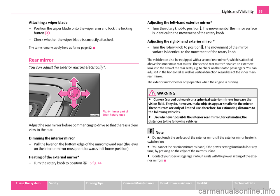
– Turn the rotary knob to position ⇒fig. 44.
Adjusting the left-hand exterior mirror*
– Turn the rotary knob to position . The movement of the mirror surface
is identical to the movement of the rotary knob.
Adjusting the right-hand exterior mirror*
– Turn the rotary knob to position . The movement of the mirror
surface is identical to the movement of the rotary knob.
The vehicle can also be equipped with a se cond rear mirror*, which is attached above the inner main rear mirror. The second rear mirror* enables an extensive look into the area of the rear seats, e.g. to check on the seated passengers. You can adjust it in the horizontal as well as vertical direction regardless of the inner main rear mirror.
The exterior mirror heater only operates when the engine is running.
WARNING
•Convex (curved outward) or a spherical exterior mirrors increase the vision field. They do, however, make objects appear smaller in the mirror. These mirrors are only of limited use, therefore, for estimating distances to the following vehicles.
•Use whenever possible the interior rear mirror, for estimating the distances to the following vehicles.
Note
•Do not touch the surfaces of the exterior mirrors if the exterior mirror heater is switched on.
•You can set the exterior mirrors by hand, if the power setting function fails at any time, by pressing on the ed ge of the mirror surface.
•Contact your specialist garage if a fault exists with the power setting of the exte- rior mirrors.
AA
Fig. 44 Inner part of door: Rotary knob
NKO A05R 20 MR08.book Page 53 Wednesday, March 28, 2007 9:42 AM
Page 56 of 248
Seats and Stowage55
Using the systemSafetyDriving TipsGeneral MaintenanceBreakdown assistancePraktikTechnical Data
Adjusting height of seat*
– Lift the seat if required by pulling or pumping lever upwards.
– Lower the seat if required by pushing or pumping lever down-
wards.
Adjust the angle of the seat backrest
– Relieve any pressure on the backrest (do not lean on it) and turn the
handwheel to adjust the angle of the backrest.
The driver's seat should be adjusted in such a way that the pedals can be pressed to the floor with slightly bent legs.
The backrest on the driver's seat should be adjusted in such a way that the upper point of the steering wheel can be easi ly reached with slightly bent arms.
WARNING
•Only adjust the driver seat when the vehicle is stationary - risk of injury!
•Take care when adjusting the seat! Adjusting the seat without care can lead to bruises or injuries.
•The backrests must not be angled too far back when driving otherwise this will affect proper operation of the seat belts and of the airbag system - risk of injury!
Head restraints
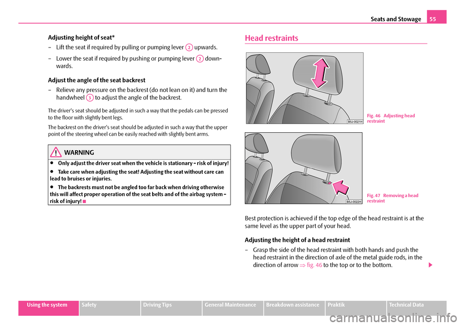
Best protection is achieved if the top edge of the head restraint is at the
same level as the uppe r part of your head.
Adjusting the height of a head restraint
– Grasp the side of the head restraint with both hands and push the
head restraint in the direction of axle of the metal guide rods, in the
direction of arrow ⇒fig. 46 to the top or to the bottom.
A2
A2
A3
Fig. 46 Adjusting head restraint
Fig. 47 Removing a head restraint
NKO A05R 20 MR08.book Page 55 Wednesday, March 28, 2007 9:42 AM
Page 58 of 248
Seats and Stowage57
Using the systemSafetyDriving TipsGeneral MaintenanceBreakdown assistancePraktikTechnical Data
Caution
•You should not kneel on the seats or otherwise apply pressure at specific points in order to avoid damaging the heating elements of the seat heaters.
•Do not clean the seats moist ⇒page 168.
Note
The seat heating should only be switched on when the engine is running. This has a significant effect of saving on the battery capacity.
Rear seats
Adjusting seats in forward/back direction
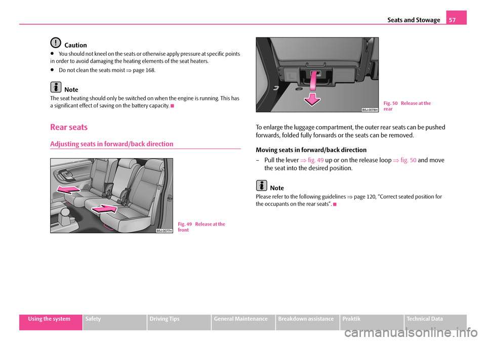
To enlarge the luggage compartment, the outer rear seats can be pushed
forwards, folded fully forwards or the seats can be removed.
Moving seats in forward/back direction
–Pull the lever ⇒fig. 49 up or on the release loop ⇒fig. 50 and move
the seat into the desired position.
Note
Please refer to the following guidelines ⇒page 120, “Correct seated position for the occupants on the rear seats”.
Fig. 49 Release at the front
Fig. 50 Release at the rear
NKO A05R 20 MR08.book Page 57 Wednesday, March 28, 2007 9:42 AM
Page 60 of 248
Seats and Stowage59
Using the systemSafetyDriving TipsGeneral MaintenanceBreakdown assistancePraktikTechnical Data
Note
Please refer to the following guidelines ⇒page 120, “Correct seated position for the occupants on the rear seats”.
NKO A05R 20 MR08.book Page 59 Wednesday, March 28, 2007 9:42 AM
Page 62 of 248
Seats and Stowage61
Using the systemSafetyDriving TipsGeneral MaintenanceBreakdown assistancePraktikTechnical Data
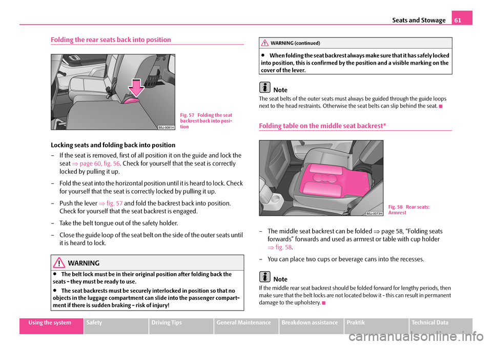
Folding the rear seats back into position
Locking seats and folding back into position
– If the seat is removed, first of all position it on the guide and lock the
seat ⇒page 60, fig. 56. Check for yourself that the seat is correctly
locked by pulling it up.
– Fold the seat into the horizontal posi tion until it is heard to lock. Check
for yourself that the seat is correctly locked by pulling it up.
– Push the lever ⇒fig. 57 and fold the backrest back into position.
Check for yourself that the seat backrest is engaged.
– Take the belt tongue out of the safety holder.
– C l o s e th e g u id e l o o p o f t h e s ea t b el t o n th e s i de o f t h e o u te r s e a t s u n t il
it is heard to lock.
WARNING
•The belt lock must be in their original position after folding back the seats - they must be ready to use.
•The seat backrests must be securely interlocked in position so that no objects in the luggage compartment ca n slide into the passenger compart- ment if there is sudden braking - risk of injury!
•When folding the seat back rest always make sure that it has safely locked into position, this is confirmed by the position and a visible marking on the cover of the lever.
Note
The seat belts of the outer seats must always be guided through the guide loops next to the head restraints. Otherwise the seat belts can slip behind the seat.
Folding table on the middle seat backrest*
– The middle seat backrest can be folded ⇒page 58, “Folding seats
forwards” forwards and used as armrest or table with cup holder
⇒ fig. 58.
– You can place two cups or beverage cans into the recesses.
Note
If the middle rear seat backrest should be folded forward for lengthy periods, then make sure that the belt locks are not located below it - this can result in permanent damage to the upholstery.
Fig. 57 Folding the seat backrest back into posi-tion
WARNING (continued)
Fig. 58 Rear seats: Armrest
NKO A05R 20 MR08.book Page 61 Wednesday, March 28, 2007 9:42 AM
Page 64 of 248
Seats and Stowage63
Using the systemSafetyDriving TipsGeneral MaintenanceBreakdown assistancePraktikTechnical Data
•On no account exceed the permissible axle loads and the permissible gross weight of the vehi cle - risk of accident!
•Never transport occupants in the luggage compartment.
Caution
Please ensure that the heating elements of the rear window heater are not damaged as a result of objects sliding in this area.
Note
•Tyre pressure must be adjusted to the load ⇒page 187, fig. 164.
•The air circulation in the interior of the car helps to prevent the windows from misting up. Stale air is diverted via the outlet nozzles into the luggage compartment below the bumper. Check for yourself that the outlet nozzles are not covered.
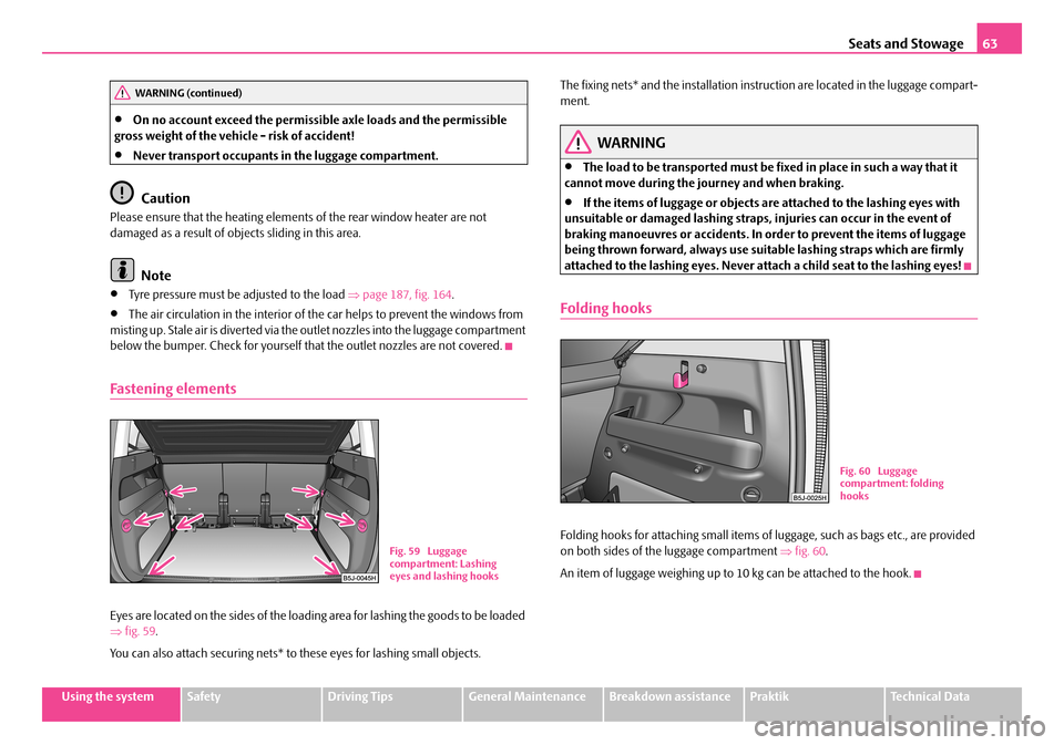
Fastening elements
Eyes are located on the sides of the loading area for lashing the goods to be loaded ⇒ fig. 59.
You can also attach securing nets* to these eyes for lashing small objects.
The fixing nets* and the installation inst ruction are located in the luggage compart- ment.
WARNING
•The load to be transported must be fixed in place in such a way that it cannot move during the journey and when braking.
•If the items of luggage or objects ar e attached to the lashing eyes with unsuitable or damaged lashing straps, injuries can occur in the event of braking manoeuvres or accidents. In order to prevent the items of luggage being thrown forward, always use suit able lashing straps which are firmly attached to the lashing eyes. Never atta ch a child seat to the lashing eyes!
Folding hooks
Folding hooks for attaching small items of luggage, such as bags etc., are provided on both sides of the luggage compartment ⇒fig. 60.
An item of luggage weighing up to 10 kg can be attached to the hook.
WARNING (continued)
Fig. 59 Luggage compartment: Lashing eyes and lashing hooks
Fig. 60 Luggage compartment: folding hooks
NKO A05R 20 MR08.book Page 63 Wednesday, March 28, 2007 9:42 AM