heater SKODA ROOMSTER 2008 1.G Owner's Manual
[x] Cancel search | Manufacturer: SKODA, Model Year: 2008, Model line: ROOMSTER, Model: SKODA ROOMSTER 2008 1.GPages: 248, PDF Size: 46.44 MB
Page 9 of 248
Cockpit8
Cockpit
General view
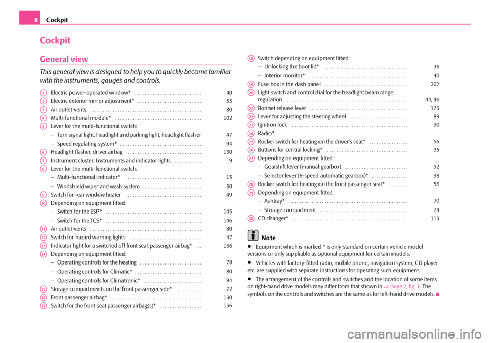
This general view is designed to help you to quickly become familiar
with the instruments, gauges and controls.
Electric power-operated window* . . . . . . . . . . . . . . . . . . . . . . . . . . .
Electric exterior mirror adjustment* . . . . . . . . . . . . . . . . . . . . . . . . . .
Air outlet vents . . . . . . . . . . . . . . . . . . . . . . . . . . . . . . . . . . . . . . . . . . . . .
Multi-functional module* . . . . . . . . . . . . . . . . . . . . . . . . . . . . . . . . . . .
Lever for the multi-functional switch:
− Turn signal light, headlight and parking light, headlight flasher
− Speed regulating system* . . . . . . . . . . . . . . . . . . . . . . . . . . . . . . . . .
Headlight flasher, driver airbag . . . . . . . . . . . . . . . . . . . . . . . . . . . . . .
Instrument cluster: Instruments and in dicator lights . . . . . . . . . . .
Lever for the multi-functional switch:
− Multi-functional indicator* . . . . . . . . . . . . . . . . . . . . . . . . . . . . . . .
− Windshield wiper and wash system . . . . . . . . . . . . . . . . . . . . . . . .
Switch for rear window heater . . . . . . . . . . . . . . . . . . . . . . . . . . . . . . .
Depending on equipment fitted:
− Switch for the ESP* . . . . . . . . . . . . . . . . . . . . . . . . . . . . . . . . . . . . . . .
− Switch for the TCS* . . . . . . . . . . . . . . . . . . . . . . . . . . . . . . . . . . . . . . .
Air outlet vents . . . . . . . . . . . . . . . . . . . . . . . . . . . . . . . . . . . . . . . . . . . . .
Switch for hazard warning lights . . . . . . . . . . . . . . . . . . . . . . . . . . . . .
Indicator light for a switched off front seat passenger airbag* . .
Depending on equipment fitted:
− Operating controls for the heating . . . . . . . . . . . . . . . . . . . . . . . . .
− Operating controls for Climatic* . . . . . . . . . . . . . . . . . . . . . . . . . . .
− Operating controls for Climatronic* . . . . . . . . . . . . . . . . . . . . . . .
Storage compartments on the front passenger side* . . . . . . . . . .
Front passenger airbag* . . . . . . . . . . . . . . . . . . . . . . . . . . . . . . . . . . . . .
Switch for the front seat passenger airbag(s)* . . . . . . . . . . . . . . . . .
Switch depending on equipment fitted:
− Unlocking the boot lid* . . . . . . . . . . . . . . . . . . . . . . . . . . . . . . . . . .
− Interior monitor* . . . . . . . . . . . . . . . . . . . . . . . . . . . . . . . . . . . . . . . .
Fuse box in the dash panel . . . . . . . . . . . . . . . . . . . . . . . . . . . . . . . . . .
Light switch and control dial for the headlight beam range regulation . . . . . . . . . . . . . . . . . . . . . . . . . . . . . . . . . . . . . . . . . . . . . . . . .
Bonnet release lever . . . . . . . . . . . . . . . . . . . . . . . . . . . . . . . . . . . . . . . .
Lever for adjusting the steering wheel . . . . . . . . . . . . . . . . . . . . . . . .
Ignition lock . . . . . . . . . . . . . . . . . . . . . . . . . . . . . . . . . . . . . . . . . . . . . . .
Radio*
Rocker switch for heating on the driver's seat* . . . . . . . . . . . . . . . .
Buttons for central locking* . . . . . . . . . . . . . . . . . . . . . . . . . . . . . . . . .
Depending on equipment fitted:
− Gearshift lever (manual gearbox) . . . . . . . . . . . . . . . . . . . . . . . . . .
− Selector lever (6-speed automatic gearbox)* . . . . . . . . . . . . . . .
Rocker switch for heating on the front passenger seat* . . . . . . . .
Depending on equipment fitted:
− Ashtray* . . . . . . . . . . . . . . . . . . . . . . . . . . . . . . . . . . . . . . . . . . . . . . . .
− Storage compartment . . . . . . . . . . . . . . . . . . . . . . . . . . . . . . . . . . . .
CD changer* . . . . . . . . . . . . . . . . . . . . . . . . . . . . . . . . . . . . . . . . . . . . . . .
Note
•Equipment which is marked * is only standard on certain vehicle model versions or only suppliable as optional equipment for certain models.
•Vehicles with factory-fitted radio, mobi le phone, navigation system, CD player etc. are supplied with separate inst ructions for operating such equipment.
•The arrangement of the controls and switches and the location of some items on right-hand drive models may differ from that shown in ⇒page 7, fig. 1. The symbols on the controls and switches are the same as for left-hand drive models.
A140
A253
A380
A4102
A5
47
94
A6130
A79
A8
13
50
A949
A10
145
146
A1180
A1247
A13136
A14
78
80
84
A1572
A16130
A17136
A18
36
40
A19207
A2044, 46
A21173
A2289
A2390
A24
A2556
A2635
A27
92
98
A2856
A29
70
74
A30113
NKO A05R 20 MR08.book Page 8 Wednesday, March 28, 2007 9:42 AM
Page 50 of 248
Lights and Visibility49
Using the systemSafetyDriving TipsGeneral MaintenanceBreakdown assistancePraktikTechnical Data
Lighting of storage compartment on the front passenger side
– When opening the flap of the storage compartment on the front
passenger side the lighting in the storage compartment comes on.
– The light switches on automatically when the parking light is switched
on and goes out when the flap is closed.
The interior light is switched on for abou t 20 seconds when a vehicle with a central locking system is unlocked, when a door is opened or when the ignition key is removed. The requirement for this is that the switch is in the door contact position. The inner light goes out out immediately after the ignition is switched on.
A time delay switch* causes the inner lighti ng on vehicles without a central locking system stays on for a few seconds after the doors have been closed. The inner light goes out out immediately after the ignition is switched on.
The interior lighting is switched off af ter about 30 minutes when a door has been left open in order to avoid discharging the battery of the vehicle.
Rear interior lighting*
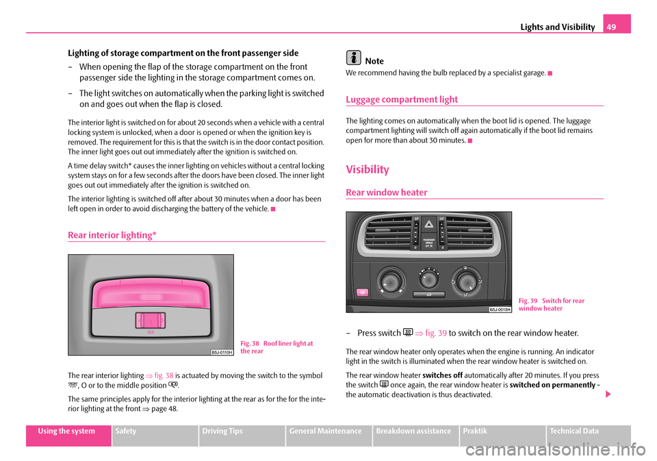
The rear interior lighting ⇒fig. 38 is actuated by moving the switch to the symbol , O or to the middle position .
The same principles apply for the interior lighting at the rear as for the for the inte- rior lighting at the front ⇒page 48.
Note
We recommend having the bulb replaced by a specialist garage.
Luggage compartment light
The lighting comes on automatically when the boot lid is opened. The luggage compartment lighting will switch off again automatically if the boot lid remains open for more than about 30 minutes.
Visibility
Rear window heater
– Press switch ⇒fig. 39 to switch on the rear window heater.
The rear window heater only operates when the engine is running. An indicator light in the switch is illuminated when the rear window heater is switched on.
The rear window heater switches off automatically after 20 minutes. If you press the switch once again, the rear window heater is switched on permanently - the automatic deactivation is thus deactivated.
Fig. 38 Roof liner light at the rear
Fig. 39 Switch for rear window heater
NKO A05R 20 MR08.book Page 49 Wednesday, March 28, 2007 9:42 AM
Page 51 of 248
Lights and Visibility50
For the sake of the environment
You should switch off the rear window heater as soon as the rear window is clear. The reduced current consumption will have a favourable effect on fuel economy ⇒ page 157, “Saving electricity”.
Sun visors
Using the sun visors can contribute to increasing road safety.
You can pull the sun visor for the driver or front passenger out of the fixture and swivel it toward the door in the direction of the arrow ⇒fig. 40.
A vanity mirror*, which is provided with a cover, is located in the sun visor on the driver and front passenger side. Push the cover in direction of arrow .
WARNING
The sun visors must not be swivelled to the side windows into the deploy-ment area of the head airbags if any ob jects, such as ball-point pens etc. are attached to them. This might result in injuries to the occupants if the head airbag is deployed.
Windshield wiper and wash system
Windshield wiper
You can operate the windscreen wipers and automatic wipe/wash
using the windscreen wiper lever.
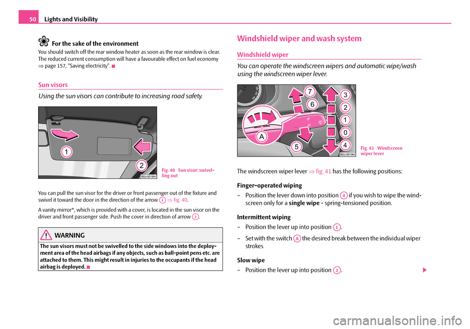
The windscreen wiper lever ⇒fig. 41 has the following positions:
Finger-operated wiping
– Position the lever down into position if you wish to wipe the wind-
screen only for a single wipe - spring-tensioned position.
Intermittent wiping
– Position the lever up into position .
– Set with the switch the desired break between the individual wiper
strokes
Slow wipe
– Position the lever up into position .
Fig. 40 Sun visor: swivel- ling out
A1
A2
Fig. 41 Windscreen wiper lever
A4
A1
AA
A2
NKO A05R 20 MR08.book Page 50 Wednesday, March 28, 2007 9:42 AM
Page 54 of 248
Lights and Visibility53
Using the systemSafetyDriving TipsGeneral MaintenanceBreakdown assistancePraktikTechnical Data
Attaching a wiper blade
– Position the wiper blade onto th e wiper arm and lock the locking
button .
– Check whether the wiper blade is correctly attached.
The same remarks apply here as for ⇒page 52.
Rear mirror
You can adjust the exterior mirrors electrically*.
Adjust the rear mirror before commencing to drive so that there is a clear
view to the rear.
Dimming the interior mirror
– Pull the lever on the bottom edge of the mirror toward rear (the lever
on the interior mirror must point forwards in it home position).
Heating of the external mirror*
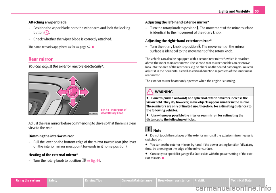
– Turn the rotary knob to position ⇒fig. 44.
Adjusting the left-hand exterior mirror*
– Turn the rotary knob to position . The movement of the mirror surface
is identical to the movement of the rotary knob.
Adjusting the right-hand exterior mirror*
– Turn the rotary knob to position . The movement of the mirror
surface is identical to the movement of the rotary knob.
The vehicle can also be equipped with a se cond rear mirror*, which is attached above the inner main rear mirror. The second rear mirror* enables an extensive look into the area of the rear seats, e.g. to check on the seated passengers. You can adjust it in the horizontal as well as vertical direction regardless of the inner main rear mirror.
The exterior mirror heater only operates when the engine is running.
WARNING
•Convex (curved outward) or a spherical exterior mirrors increase the vision field. They do, however, make objects appear smaller in the mirror. These mirrors are only of limited use, therefore, for estimating distances to the following vehicles.
•Use whenever possible the interior rear mirror, for estimating the distances to the following vehicles.
Note
•Do not touch the surfaces of the exterior mirrors if the exterior mirror heater is switched on.
•You can set the exterior mirrors by hand, if the power setting function fails at any time, by pressing on the ed ge of the mirror surface.
•Contact your specialist garage if a fault exists with the power setting of the exte- rior mirrors.
AA
Fig. 44 Inner part of door: Rotary knob
NKO A05R 20 MR08.book Page 53 Wednesday, March 28, 2007 9:42 AM
Page 58 of 248
Seats and Stowage57
Using the systemSafetyDriving TipsGeneral MaintenanceBreakdown assistancePraktikTechnical Data
Caution
•You should not kneel on the seats or otherwise apply pressure at specific points in order to avoid damaging the heating elements of the seat heaters.
•Do not clean the seats moist ⇒page 168.
Note
The seat heating should only be switched on when the engine is running. This has a significant effect of saving on the battery capacity.
Rear seats
Adjusting seats in forward/back direction
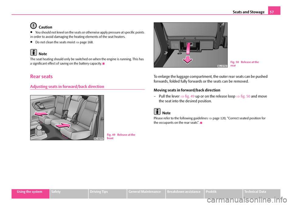
To enlarge the luggage compartment, the outer rear seats can be pushed
forwards, folded fully forwards or the seats can be removed.
Moving seats in forward/back direction
–Pull the lever ⇒fig. 49 up or on the release loop ⇒fig. 50 and move
the seat into the desired position.
Note
Please refer to the following guidelines ⇒page 120, “Correct seated position for the occupants on the rear seats”.
Fig. 49 Release at the front
Fig. 50 Release at the rear
NKO A05R 20 MR08.book Page 57 Wednesday, March 28, 2007 9:42 AM
Page 64 of 248
Seats and Stowage63
Using the systemSafetyDriving TipsGeneral MaintenanceBreakdown assistancePraktikTechnical Data
•On no account exceed the permissible axle loads and the permissible gross weight of the vehi cle - risk of accident!
•Never transport occupants in the luggage compartment.
Caution
Please ensure that the heating elements of the rear window heater are not damaged as a result of objects sliding in this area.
Note
•Tyre pressure must be adjusted to the load ⇒page 187, fig. 164.
•The air circulation in the interior of the car helps to prevent the windows from misting up. Stale air is diverted via the outlet nozzles into the luggage compartment below the bumper. Check for yourself that the outlet nozzles are not covered.
Fastening elements
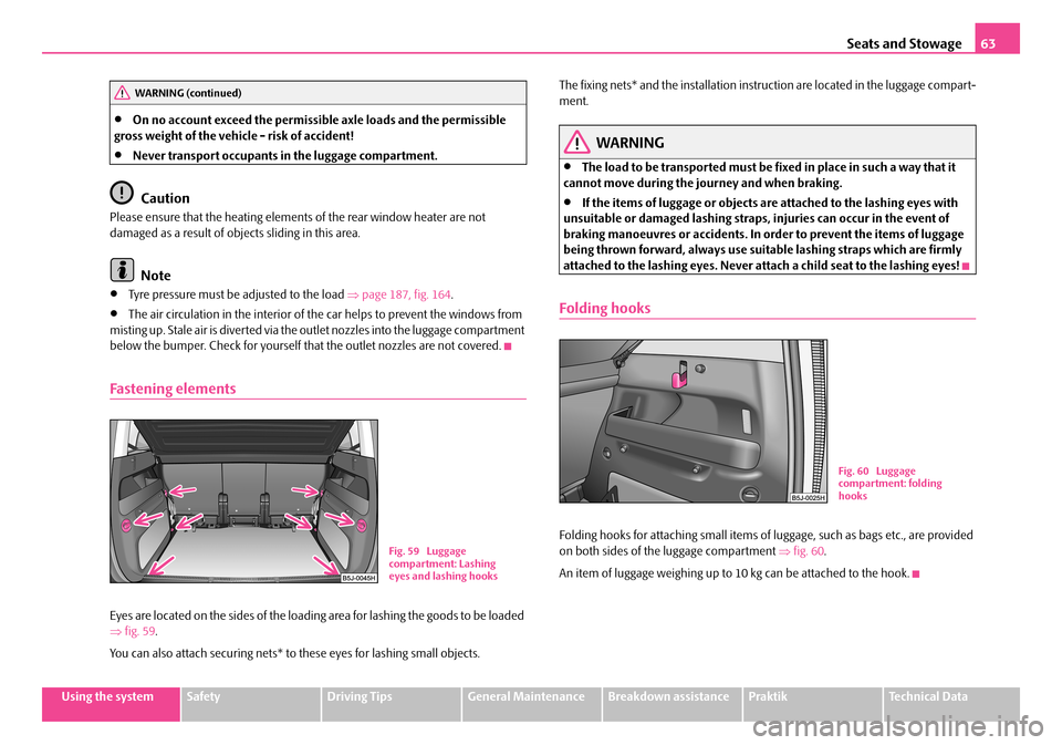
Eyes are located on the sides of the loading area for lashing the goods to be loaded ⇒ fig. 59.
You can also attach securing nets* to these eyes for lashing small objects.
The fixing nets* and the installation inst ruction are located in the luggage compart- ment.
WARNING
•The load to be transported must be fixed in place in such a way that it cannot move during the journey and when braking.
•If the items of luggage or objects ar e attached to the lashing eyes with unsuitable or damaged lashing straps, injuries can occur in the event of braking manoeuvres or accidents. In order to prevent the items of luggage being thrown forward, always use suit able lashing straps which are firmly attached to the lashing eyes. Never atta ch a child seat to the lashing eyes!
Folding hooks
Folding hooks for attaching small items of luggage, such as bags etc., are provided on both sides of the luggage compartment ⇒fig. 60.
An item of luggage weighing up to 10 kg can be attached to the hook.
WARNING (continued)
Fig. 59 Luggage compartment: Lashing eyes and lashing hooks
Fig. 60 Luggage compartment: folding hooks
NKO A05R 20 MR08.book Page 63 Wednesday, March 28, 2007 9:42 AM
Page 66 of 248
Seats and Stowage65
Using the systemSafetyDriving TipsGeneral MaintenanceBreakdown assistancePraktikTechnical Data
The luggage compartment cover
You can use the luggage compartment cover behind the head
restraints for storing light and soft items.
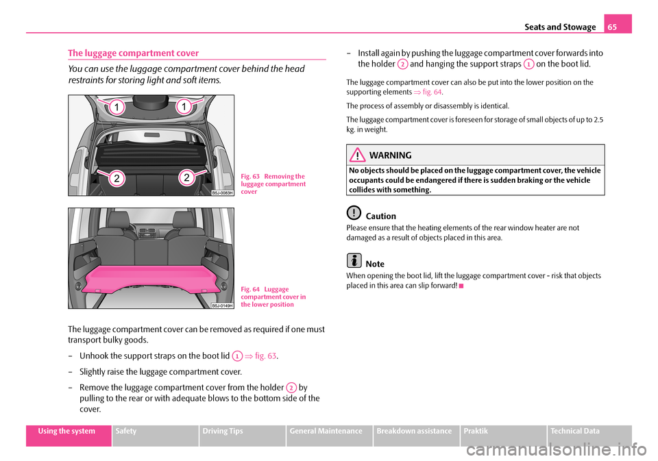
The luggage compartment cover can be removed as required if one must
transport bulky goods.
– Unhook the support stra ps on the boot lid ⇒fig. 63.
– Slightly raise the luggage compartment cover.
– Remove the luggage compartment cover from the holder by
pulling to the rear or with adequate blows to the bottom side of the
cover.
– Install again by pushing the luggage compartment cover forwards into
the holder and hanging the suppo rt straps on the boot lid.
The luggage compartment cover can also be put into the lower position on the supporting elements ⇒fig. 64.
The process of assembly or disassembly is identical.
The luggage compartment cover is foreseen fo r storage of small objects of up to 2.5 kg. in weight.
WARNING
No objects should be placed on the luggage compartment cover, the vehicle occupants could be endangered if th ere is sudden braking or the vehicle collides with something.
Caution
Please ensure that the heating elements of the rear window heater are not damaged as a result of obje cts placed in this area.
Note
When opening the boot lid, lift the luggage compartment cover - risk that objects placed in this area can slip forward!
Fig. 63 Removing the luggage compartment cover
Fig. 64 Luggage compartment cover in the lower position
A1
A2
A2A1
NKO A05R 20 MR08.book Page 65 Wednesday, March 28, 2007 9:42 AM
Page 167 of 248
Taking care of your vehicle and cleaning the vehicle166
Plastic parts
External plastic parts are cleaned by normal washing. Plastic parts and synthetic leather can also be treated with special solvent-free plastic cleaning agents if a damp cloth is not sufficient. Paint care pr oducts are not suitable for plastic parts.
Caution
Solvent-free cleaners attack the material and can damage it.
Windows
Only use a plastic ice scraper for removing snow and ice from the windows and mirrors. You should not move the ice scraper forward and backward but in one direction on the window which you are clea ning in order to avoid any damage to the surface of the glass.
You can best remove residues of rubber, oil, grease, wax or silicone by using a special window cleaner or a special silicone remover.
You should also clean the windows regularly from the inside.
Do not use window leathers which you have used to polish the vehicle body to dry off the windows. Residues of preservati ves in the window leather can dirty the window and reduce visibility.
Do not affix any stickers over the inside of the rear window to avoid damage to the heating elements of the rear window heater .
We recommend using a preservative from Škoda genuine accessories offered by your Škoda dealer.
Caution
•Never remove snow or ice from the glass parts with warm or hot water - risk of formation of cracks in the glass!
•When removing snow or ice from the windows and mirror lenses make sure not to damage the paintwork of the vehicle.
The headlight lenses
Please do not use any aggres sive cleaning or chemical solvent products - risk of damage to the plastic lenses Please use soap and clean warm water.
Caution
Never wipe the headlights dry and do not use any sharp objects for cleaning the plastic lenses, this may result in damage to the protective paintwork and conse- quently in formation of cracks on the head light lenses, e.g through effect of chem- ical products.
Door and window seals
The rubber seals on the doors, boot lid, bonnet and windows remain supple and last longer if you treat them from time to time with a rubber care product (e.g. with a spray with silicone-free oil). You also avoid premature wear of the seals and prevent leakages in this way. It is also easier to open the doors. Rubber seals which are well cared for also do not stick together in cold winter weather.
Locks
We recommend that you use the spray from Škoda original accessories with regreasing and anticorrosive effect for de-icing locks.
Note
When washing your vehicle, ensure that as little water as possible gets into the locks.
NKO A05R 20 MR08.book Page 166 Wednesday, March 28, 2007 9:42 AM
Page 209 of 248
Fuses and light bulbs208
Note
We recommend that you have these fuses replaced by a specialist garage.
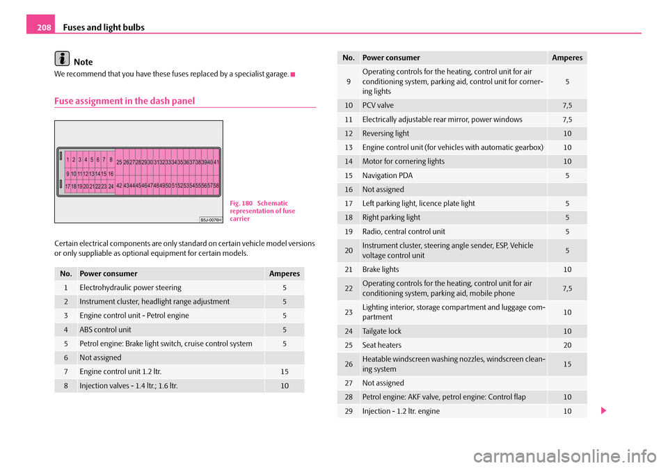
Fuse assignment in the dash panel
Certain electrical components are only st andard on certain vehicle model versions or only suppliable as optional equipment for certain models.
No.Power consumerAmperes
1Electrohydraulic power steering5
2Instrument cluster, headlight range adjustment5
3Engine control unit - Petrol engine5
4ABS control unit5
5Petrol engine: Brake light switch, cruise control system5
6Not assigned
7Engine control unit 1.2 ltr.15
8Injection valves - 1.4 ltr.; 1.6 ltr.10
Fig. 180 Schematic representation of fuse carrier
9Operating controls for the he ating, control unit for air conditioning system, parking aid, control unit for corner- ing lights5
10PCV valve7,5
11Electrically adjustable rear mirror, power windows7,5
12Reversing light10
13Engine control unit (for vehi cles with automatic gearbox)10
14Motor for cornering lights10
15Navigation PDA5
16Not assigned
17Left parking light, licence plate light5
18Right parking light5
19Radio, central control unit5
20Instrument cluster, steering angle sender, ESP, Vehicle voltage control unit5
21Brake lights10
22Operating controls for the he ating, control unit for air conditioning system, parking aid, mobile phone7,5
23Lighting interior, storage compartment and luggage com-partment10
24Tailgate lock10
25Seat heaters20
26Heatable windscreen washing nozzles, windscreen clean- ing system15
27Not assigned
28Petrol engine: AKF valve, petrol engine: Control flap10
29Injection - 1.2 ltr. engine10
No.Power consumerAmperes
NKO A05R 20 MR08.book Page 208 Wednesday, March 28, 2007 9:42 AM
Page 210 of 248
Fuses and light bulbs209
Using the systemSafetyDriving TipsGeneral MaintenanceBreakdown assistancePraktikTechnical Data
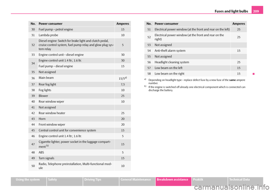
30Fuel pump - petrol engine15
31Lambda probe10
32Diesel engine: Switch for brake light and clutch pedal, cruise control system, fuel pump relay and glow plug sys- tem relay5
33Engine control unit - diesel engine30
34Engine control unit 1.4 ltr.; 1.6 ltr.30
Fuel pump - diesel engine15
35Not assigned
36Main beam15/5a)
37Rear fog light7,5
38Fog lights10
39Blower25
40Rear window wiper10
41Not assigned
42Rear window heater25
43Horn20
44Front window wiper20
45Central control unit for convenience system15
46Engine control unit 1.4 ltr.; 1.6 ltr.5
47Cigarette lighter, power sock et in the luggage compart-
ment b)15
48ABS5
49Tu r n s i g n a l s15
50Radio, Telephone preinstallat ion, Multi-functional mod- ule10
No.Power consumerAmperes
51Electrical power window (at the front and rear on the left)25
52Electrical power window (at the front and rear on the right)25
53Not assigned
54Anti-theft alarm system15
55Not assigned
56Headlight cleaning system25
57Low beam on the left15
58Low beam on the right15
a)Depending on headlight type - replace defect fuse by a new fuse of the same ampere number.b)If the engine is switched off already one electrical component which is connected can discharge the battery.
No.Power consumerAmperes
NKO A05R 20 MR08.book Page 209 Wednesday, March 28, 2007 9:42 AM