radio SKODA ROOMSTER 2009 1.G Owner's Manual
[x] Cancel search | Manufacturer: SKODA, Model Year: 2009, Model line: ROOMSTER, Model: SKODA ROOMSTER 2009 1.GPages: 263, PDF Size: 32.25 MB
Page 3 of 263
Introduction 2
On-board literature
The on-board literature for your vehicle consists of this “Owner's
Manual” as well as a “Service schedule” and a “Help on the road”. There
can also be a variety of other additional operating manuals and instruc-
tions on-board (e.g. an operating manual for the radio) depending on the
vehicle model and equipment.
If one of the publications listed above is missing, please contact a
specialist garage immediately, where one will be glad to assist you in such
matters.
One should note that the details given in the vehicle's papers always
take precedence over those in the Owner's Manual.
Owner's Manual
This Owner's Manual describes the current scope of equipment.
Certain items of equipment listed are only installed later on and only
envisaged for particular markets. The illustrations can differ in minor
details from your vehicle; they are only intended for general information.
In addition to information regarding all the controls and equipment, the
Owner's Manual also contains important information regarding care and
operation for your safety and also to retain the value of your vehicle. To
provide you with valuable tips and aids. You will learn how you can
operate your vehicle safely, economically and in an environmentally
conscious way.
For safety reasons, please also pay attention to the information on
accessories, modifications and replacement of parts ⇒page 204.
The other chapters of the Owner's Manual are also important, however,
for proper treatment of your car - in addition to regular care and mainte-
nance - helps to retain its value and in many cases is also one of the
conditions for possible warranty claims.The Service schedule
Contains:
•
Vehicle data;
•
Service intervals;
•
Overview of the service work;
•
Service proof;
•
Confirmation of mobility warranty (only valid in certain countries);
•
important information on the warranty.
The confirmations of the carried out service work are one of the condi-
tions for possible warranty claims.
Please always present the Service schedule when you take your car to a
specialist garage.
If the Service schedule is missing or worn, please contact the specialist
garage where your car is serviced regularly. You will receive a duplicate, in
which the previously carried out service work are confirmed.
Help on the road
contains the most important telephone numbers in individual countries
as well as the addresses and telephone numbers of Škoda importers.
s29g.4.book Page 2 Wednesday, June 17, 2009 9:54 AM
Page 4 of 263
Contents3
Using the system
Safety
Driving Tips
General Maintenance
Breakdown assistance
Praktik
Technical Data
ContentsLayout of this Owner's Manual
(explanations)
. . . . . . . . . . . . . . . . . . . . . . . . . .
Using the system
. . . . . . . . . . . . . . . . . . . . . .
Cockpit
. . . . . . . . . . . . . . . . . . . . . . . . . . . . . . . . . . . . . . . .
General view . . . . . . . . . . . . . . . . . . . . . . . . . . . . . . . . .
The brief instruction
. . . . . . . . . . . . . . . . . . . . . . . . . .
Basic functions and important information . . . . .
Instruments and Indicator/Warning Lights
. . .
General view of the instrument cluster . . . . . . . . .
Engine revolutions counter . . . . . . . . . . . . . . . . . . . .
Coolant temperature gauge* . . . . . . . . . . . . . . . . . .
Fuel gauge* . . . . . . . . . . . . . . . . . . . . . . . . . . . . . . . . . .
Counter for distance driven . . . . . . . . . . . . . . . . . . .
Service Interval Display . . . . . . . . . . . . . . . . . . . . . . .
Digital clock . . . . . . . . . . . . . . . . . . . . . . . . . . . . . . . . . .
Multi-functional indicator (onboard computer)*
Information display* . . . . . . . . . . . . . . . . . . . . . . . . . .
Auto Check Control . . . . . . . . . . . . . . . . . . . . . . . . . . .
Warning lights . . . . . . . . . . . . . . . . . . . . . . . . . . . . . . . .
Unlocking and locking
. . . . . . . . . . . . . . . . . . . . . . . .
Key . . . . . . . . . . . . . . . . . . . . . . . . . . . . . . . . . . . . . . . . . .
Locking . . . . . . . . . . . . . . . . . . . . . . . . . . . . . . . . . . . . . .
Child safety lock . . . . . . . . . . . . . . . . . . . . . . . . . . . . . .
Central locking system* . . . . . . . . . . . . . . . . . . . . . . .
Remote control* . . . . . . . . . . . . . . . . . . . . . . . . . . . . . .
Anti-theft alarm system* . . . . . . . . . . . . . . . . . . . . . .
Interior monitor* and towing protection
monitoring* . . . . . . . . . . . . . . . . . . . . . . . . . . . . . . . . . .
Electrical power windows* . . . . . . . . . . . . . . . . . . . .
Panorama roof* . . . . . . . . . . . . . . . . . . . . . . . . . . . . . .
Lights and Visibility
. . . . . . . . . . . . . . . . . . . . . . . . . . .
Lights . . . . . . . . . . . . . . . . . . . . . . . . . . . . . . . . . . . . . . . .
Interior lighting . . . . . . . . . . . . . . . . . . . . . . . . . . . . . . .
Visibility . . . . . . . . . . . . . . . . . . . . . . . . . . . . . . . . . . . . .
Windshield wiper and wash system . . . . . . . . . . . .
Rear mirror . . . . . . . . . . . . . . . . . . . . . . . . . . . . . . . . . .
Seats and Storage
. . . . . . . . . . . . . . . . . . . . . . . . . . . . .
Front seats . . . . . . . . . . . . . . . . . . . . . . . . . . . . . . . . . . .
Head restraints . . . . . . . . . . . . . . . . . . . . . . . . . . . . . . .
Heating the front seats* . . . . . . . . . . . . . . . . . . . . . . .
Rear seats . . . . . . . . . . . . . . . . . . . . . . . . . . . . . . . . . . . .
Pedals . . . . . . . . . . . . . . . . . . . . . . . . . . . . . . . . . . . . . . .
luggage compartment . . . . . . . . . . . . . . . . . . . . . . . .
Variable loading floor* . . . . . . . . . . . . . . . . . . . . . . . .
Bicycle carrier* . . . . . . . . . . . . . . . . . . . . . . . . . . . . . . .
The roof luggage rack system* . . . . . . . . . . . . . . . . .
Front cup holder . . . . . . . . . . . . . . . . . . . . . . . . . . . . .
Rear cup holder* . . . . . . . . . . . . . . . . . . . . . . . . . . . . .
Note holder . . . . . . . . . . . . . . . . . . . . . . . . . . . . . . . . . .
Ashtray* . . . . . . . . . . . . . . . . . . . . . . . . . . . . . . . . . . . . .
Cigarette lighter* and power sockets* . . . . . . . . . .
Storage compartments . . . . . . . . . . . . . . . . . . . . . . . .
Heating and air conditioning system
. . . . . . . . .
Air outlet vents . . . . . . . . . . . . . . . . . . . . . . . . . . . . . . .
Recirculated air mode . . . . . . . . . . . . . . . . . . . . . . . .
Heating . . . . . . . . . . . . . . . . . . . . . . . . . . . . . . . . . . . . . .
Climatic (semi-automatic air conditioning
system)* . . . . . . . . . . . . . . . . . . . . . . . . . . . . . . . . . . . . .
Climatronic (automatic air conditioning)* . . . . . .
Starting-off and Driving
. . . . . . . . . . . . . . . . . . . . . . .
Setting steering wheel position . . . . . . . . . . . . . . . .
Ignition lock . . . . . . . . . . . . . . . . . . . . . . . . . . . . . . . . . .
Starting the engine . . . . . . . . . . . . . . . . . . . . . . . . . . . Switching off the engine . . . . . . . . . . . . . . . . . . . . . .
Shifting (manual gearbox) . . . . . . . . . . . . . . . . . . . . .
Handbrake . . . . . . . . . . . . . . . . . . . . . . . . . . . . . . . . . . .
Parking aid* . . . . . . . . . . . . . . . . . . . . . . . . . . . . . . . . . .
Cruise control system (CCS)* . . . . . . . . . . . . . . . . . .
Automatic gearbox
. . . . . . . . . . . . . . . . . . . . . . . . . . .
6-speed automatic gearbox* . . . . . . . . . . . . . . . . . .
Communication
. . . . . . . . . . . . . . . . . . . . . . . . . . . . . .
Operating the radio . . . . . . . . . . . . . . . . . . . . . . . . . . .
Radio and mobile phone operation . . . . . . . . . . . .
Universal telephone preinstallation with voice
control* . . . . . . . . . . . . . . . . . . . . . . . . . . . . . . . . . . . . .
Inserting the mobile phone with the adapter* . .
Mobile phone operation . . . . . . . . . . . . . . . . . . . . . .
Voice commands . . . . . . . . . . . . . . . . . . . . . . . . . . . . .
Enter PIN code . . . . . . . . . . . . . . . . . . . . . . . . . . . . . . .
Dial number . . . . . . . . . . . . . . . . . . . . . . . . . . . . . . . . .
Repeat last call . . . . . . . . . . . . . . . . . . . . . . . . . . . . . . .
Phone voice phonebook* . . . . . . . . . . . . . . . . . . . . .
Bluetooth®* . . . . . . . . . . . . . . . . . . . . . . . . . . . . . . . . .
Mobile phones and two-way radio system . . . . .
Input AUX-IN* . . . . . . . . . . . . . . . . . . . . . . . . . . . . . . .
CD changer* . . . . . . . . . . . . . . . . . . . . . . . . . . . . . . . . .
Safety
. . . . . . . . . . . . . . . . . . . . . . . . . . . . . . . . . . . . . .
Passive Safety
. . . . . . . . . . . . . . . . . . . . . . . . . . . . . . . . .
Basic information . . . . . . . . . . . . . . . . . . . . . . . . . . . .
Correct seated position . . . . . . . . . . . . . . . . . . . . . . .
Seat belts
. . . . . . . . . . . . . . . . . . . . . . . . . . . . . . . . . . . . . .
Why seat belts? . . . . . . . . . . . . . . . . . . . . . . . . . . . . . .
The physical principle of a frontal collision . . . . . 6
9
11
11
12
12
18
18
18
19
19
20
20
22
22
25
27
29
39
39
41
41
42
46
48
49
49
5253
53
57
58
59
62
63
63
64
65
66
70
70
74
77
79
80
81
81
81
82
83
89
89
89
90
92
95
99
99
100
100102
102
103
103
104
107
107
112
112
113
114
115
116
117
117
118
118
119
121
122
123
123
127
127
127
128
132
132
133
s29g.4.book Page 3 Wednesday, June 17, 2009 9:54 AM
Page 12 of 263
Cockpit11
Using the system
Safety
Driving Tips
General Maintenance
Breakdown assistance
Praktik
Technical Data
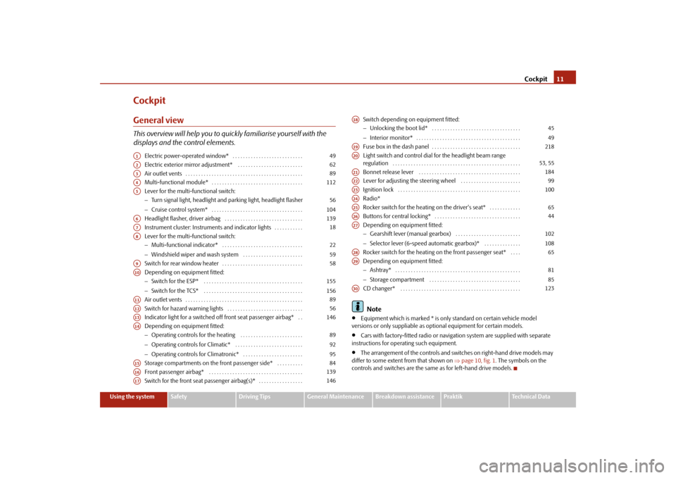
CockpitGeneral viewThis overview will help you to quickly familiarise yourself with the
displays and the control elements.
Electric power-operated window* . . . . . . . . . . . . . . . . . . . . . . . . . . .
Electric exterior mirror adjustment* . . . . . . . . . . . . . . . . . . . . . . . . .
Air outlet vents . . . . . . . . . . . . . . . . . . . . . . . . . . . . . . . . . . . . . . . . . . . . .
Multi-functional module* . . . . . . . . . . . . . . . . . . . . . . . . . . . . . . . . . . .
Lever for the multi-functional switch:
−Turn signal light, headlight and parking light, headlight flasher
−Cruise control system* . . . . . . . . . . . . . . . . . . . . . . . . . . . . . . . . . . .
Headlight flasher, driver airbag . . . . . . . . . . . . . . . . . . . . . . . . . . . . . .
Instrument cluster: Instruments and indicator lights . . . . . . . . . . .
Lever for the multi-functional switch:
−Multi-functional indicator* . . . . . . . . . . . . . . . . . . . . . . . . . . . . . . .
−Windshield wiper and wash system . . . . . . . . . . . . . . . . . . . . . . .
Switch for rear window heater . . . . . . . . . . . . . . . . . . . . . . . . . . . . . . .
Depending on equipment fitted:
−Switch for the ESP* . . . . . . . . . . . . . . . . . . . . . . . . . . . . . . . . . . . . . .
−Switch for the TCS* . . . . . . . . . . . . . . . . . . . . . . . . . . . . . . . . . . . . . .
Air outlet vents . . . . . . . . . . . . . . . . . . . . . . . . . . . . . . . . . . . . . . . . . . . . .
Switch for hazard warning lights . . . . . . . . . . . . . . . . . . . . . . . . . . . . .
Indicator light for a switched off front seat passenger airbag* . .
Depending on equipment fitted:
−Operating controls for the heating . . . . . . . . . . . . . . . . . . . . . . . .
−Operating controls for Climatic* . . . . . . . . . . . . . . . . . . . . . . . . . .
−Operating controls for Climatronic* . . . . . . . . . . . . . . . . . . . . . . .
Storage compartments on the front passenger side* . . . . . . . . . .
Front passenger airbag* . . . . . . . . . . . . . . . . . . . . . . . . . . . . . . . . . . . .
Switch for the front seat passenger airbag(s)* . . . . . . . . . . . . . . . . . Switch depending on equipment fitted:
−Unlocking the boot lid* . . . . . . . . . . . . . . . . . . . . . . . . . . . . . . . . . .
−Interior monitor* . . . . . . . . . . . . . . . . . . . . . . . . . . . . . . . . . . . . . . . .
Fuse box in the dash panel . . . . . . . . . . . . . . . . . . . . . . . . . . . . . . . . . .
Light switch and control dial for the headlight beam range
regulation . . . . . . . . . . . . . . . . . . . . . . . . . . . . . . . . . . . . . . . . . . . . . . . . .
Bonnet release lever . . . . . . . . . . . . . . . . . . . . . . . . . . . . . . . . . . . . . . .
Lever for adjusting the steering wheel . . . . . . . . . . . . . . . . . . . . . . .
Ignition lock . . . . . . . . . . . . . . . . . . . . . . . . . . . . . . . . . . . . . . . . . . . . . . .
Radio*
Rocker switch for the heating on the driver's seat* . . . . . . . . . . . .
Buttons for central locking* . . . . . . . . . . . . . . . . . . . . . . . . . . . . . . . . .
Depending on equipment fitted:
−Gearshift lever (manual gearbox) . . . . . . . . . . . . . . . . . . . . . . . . .
−Selector lever (6-speed automatic gearbox)* . . . . . . . . . . . . . .
Rocker switch for the heating on the front passenger seat* . . . .
Depending on equipment fitted:
−Ashtray* . . . . . . . . . . . . . . . . . . . . . . . . . . . . . . . . . . . . . . . . . . . . . . . .
−Storage compartment . . . . . . . . . . . . . . . . . . . . . . . . . . . . . . . . . . .
CD changer* . . . . . . . . . . . . . . . . . . . . . . . . . . . . . . . . . . . . . . . . . . . . . .
Note
•
Equipment which is marked * is only standard on certain vehicle model
versions or only suppliable as optional equipment for certain models.
•
Cars with factory-fitted radio or navigation system are supplied with separate
instructions for operating such equipment.
•
The arrangement of the controls and switches on right-hand drive models may
differ to some extent from that shown on ⇒page 10, fig. 1. The symbols on the
controls and switches are the same as for left-hand drive models.
A1
49
A2
62
A3
89
A4
112
A5
56
104
A6
139
A7
18
A8
22
59
A9
58
A10
155
156
A11
89
A12
56
A13
146
A14
89
92
95
A15
84
A16
139
A17
146
A18
45
49
A19
218
A20
53, 55
A21
184
A22
99
A23
100
A24A25
65
A26
44
A27
102
108
A28
65
A29
81
85
A30
123
s29g.4.book Page 11 Wednesday, June 17, 2009 9:54 AM
Page 26 of 263
Instruments and Indicator/Warning Lights25
Using the system
Safety
Driving Tips
General Maintenance
Breakdown assistance
Praktik
Technical Data
Driving timeThe driving time which has elapsed since the memory was last erased, appears in
the display ⇒page 22. If you wish to calculate the driving time from a particular
time of day you must first erase the memory at this moment in time by pressing the
button ⇒page 23, fig. 22.
The maximum time indicated in both switch positions is 99 hours and 59 minutes.
The indicator is set back to null if this period is exceeded.Distance drivenThe distance driven since the memory was last erased appears in the display
⇒page 22. If you wish to calculate the distance driven from a particular time of day
you must first erase the memory at this moment in time by pressing the button
⇒page 23, fig. 22.
The maximum distance indicated in both switch positions is 9 999 km. The indicator
is set back to null if this period is exceeded.Average speedThe average speed since the memory was last erased is shown in the display in
km/hour ⇒page 22. If you wish to determine the average speed over a certain
period of time you must first erase the memory at the start of the new measure-
ment using the button ⇒page 23, fig. 22.
A zero appears in the display for the first 100 m you drive after erasing the
memory.
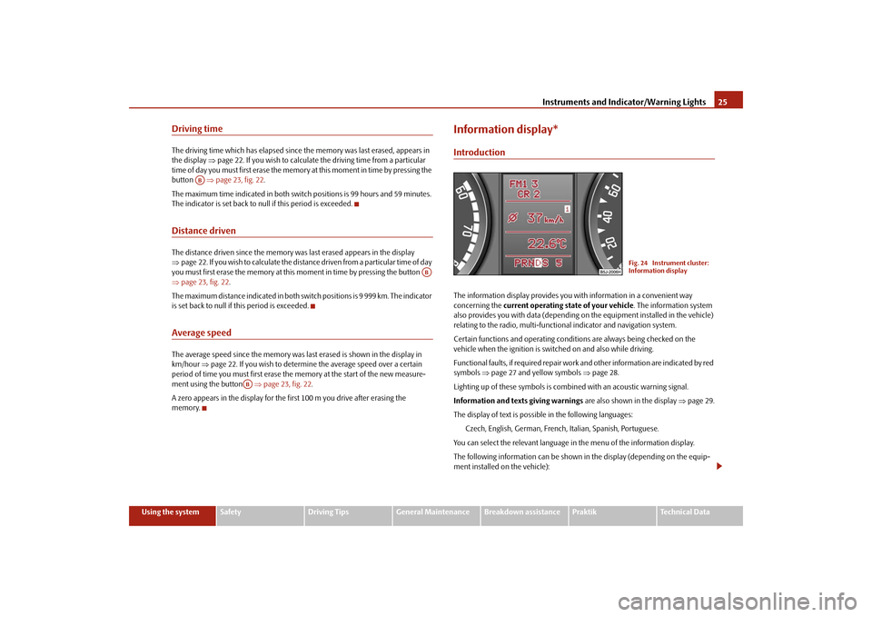
Information display*IntroductionThe information display provides you with information in a convenient way
concerning the current operating state of your vehicle. The information system
also provides you with data (depending on the equipment installed in the vehicle)
relating to the radio, multi-functional indicator and navigation system.
Certain functions and operating conditions are always being checked on the
vehicle when the ignition is switched on and also while driving.
Functional faults, if required repair work and other information are indicated by red
symbols ⇒page 27 and yellow symbols ⇒page 28.
Lighting up of these symbols is combined with an acoustic warning signal.
Information and texts giving warnings are also shown in the display ⇒page 29.
The display of text is possible in the following languages:
Czech, English, German, French, Italian, Spanish, Portuguese.
You can select the relevant language in the menu of the information display.
The following information can be shown in the display (depending on the equip-
ment installed on the vehicle):
AB
AB
AB
Fig. 24 Instrument cluster:
Information display
s29g.4.book Page 25 Wednesday, June 17, 2009 9:54 AM
Page 41 of 263
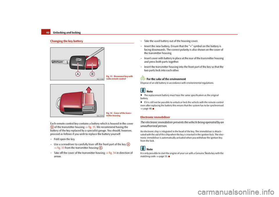
Unlocking and locking 40Changing the key batteryEach remote control key contains a battery which is housed in the cover
of the transmitter housing ⇒fig. 33. We recommend having the
battery of the key replaced by a specialist garage. You should, however,
proceed as follows if you wish to replace the battery yourself:
– Fold open the key.
– Use a screwdriver to carefully lever off the front part of the key
⇒fig. 33 from the transmitter housing .
– Take off the cover of the transmitter housing ⇒fig. 34 in direction of
arrow.– Take the used battery out of the housing cover.
– Insert the new battery. Ensure that the “+” symbol on the battery is
facing downwards. The correct polarity is also shown on the cover of
the transmitter housing.
– Insert cover with battery in place at the rear of the transmitter housing
and press both parts together.
– Insert the transmitter housing into the front part of the key so that the
two parts lock into each other.
For the sake of the environment
Dispose of an old battery in accordance with environmental regulations.
Note
•
The replacement battery must have the same specification as the original
battery.
•
If it is still not be possible to unlock or lock the vehicle with the remote control
even after replacing the battery this means that the system has to be synchronised
⇒page 48.
Electronic immobiliser
The electronic immobiliser prevents the vehicle being operated by an
unauthorised person.An electronic chip is integrated in the head of the key. The immobiliser is deacti-
vated with the aid of this chip when the key is inser ted in the ignition lock. The elec-
tronic immobiliser is automatically activated when you withdraw the ignition key
from the lock.
Note
It is only possible to start the engine of your car with a Genuine Škoda key with the
matching code ⇒page 33.
Fig. 33 Disconnect key with
radio remote controlFig. 34 Cover of the trans-
mitter housing
AB
AA
AB
s29g.4.book Page 40 Wednesday, June 17, 2009 9:54 AM
Page 48 of 263
Unlocking and locking47
Using the system
Safety
Driving Tips
General Maintenance
Breakdown assistance
Praktik
Technical Data
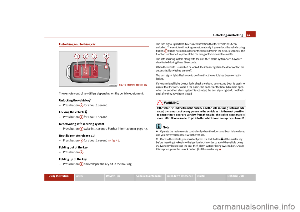
Unlocking and locking carThe remote control key differs depending on the vehicle equipment.
Unlocking the vehicle
– Press button for about 1 second.
Locking the vehicle
– Press button for about 1 second.
Deactivating safe securing system
– Press button twice in 1 seconds. Further information ⇒page 42.
Boot lid remote release
– Press button for about 1 second ⇒fig. 41.
Folding out of the key
– Press button .
Folding up of the key
– Press button and collapse the key bit in the housing.
The turn signal lights flash twice as confirmation that the vehicle has been
unlocked. The vehicle will lock again automatically if you unlock the vehicle using
button but do not open a door or the boot lid within the next 30 seconds. This
function is intended to prevent the car being unlocked unintentionally.
The safe securing system along with the anti-theft alarm system* are, however,
deactivated during these 30 seconds.
When the vehicle is unlocked or locked, the interior lights in the door contact are
automatically switched on or off.
The turn signal lights flash once to confirm that the vehicle has been correctly
locked.
If the turn signal lights do not flash, check the doors, bonnet and boot lid again to
ensure that they are closed. If the doors, the bonnet or the boot lid remain open
when the anti-theft alarm system* is activated, the turn signal lights do not flash
until after they have been closed.
WARNING
If the vehicle is locked from the outside and the safe securing system is acti-
vated, there must not be any person in the vehicle as it is then not possible
to open either a door or a window from the inside. The locked doors make it
more difficult for rescuers to get into the vehicle in an emergency - hazard!
Note
•
Operate the radio remote control only when the doors and boot lid are closed
and you have visual contact with the vehicle.
•
Once in the vehicle, you must not press the lock button
of the master key
before inserting the key into the ignition lock in order to avoid the vehicle being
inadvertently locked and the anti-theft alarm system* being switched on. Should
this happen, press the unlock button
of the master key.
Fig. 41 Remote control key
A1A3A2A2A4A4
A1
s29g.4.book Page 47 Wednesday, June 17, 2009 9:54 AM
Page 49 of 263
Unlocking and locking 48Synchonisation of the remote controlIf the vehicle cannot be unlocked by actuating the remote control system then it is
possible that the code in the key and the control unit in the vehicle are no longer
synchronised. This can occur when the buttons on the radio-operated key are actu-
ated a number of times outside of the operative range of the equipment or the
battery on the remote control was replaced.
This means it is necessary to synchronise the code as follows:•
press any button on the remote control;
•
pressing of the button means that the door will unlock with the key within 1
minute.
Anti-theft alarm system*The anti-theft alarm system increases the level of protection against people seeking
to break into the vehicle. The system triggers audible and visual warning signals if
an attempt is made to break into the vehicle.
How is the alarm system switched on?
The anti-theft alarm system is activated automatically when the vehicle is locked
with the key in the driver's door or when locking with the remote control. It is acti-
vated 30 seconds after locking the door.
How is the alarm system switched off?
The anti-theft alarm system is switched off if the vehicle is unlocked by only using
the remote control. The vehicle is automatically locked again if the vehicle is not
opened within 30 seconds after reactivating the anti-theft alarm system.
Once you unlock the vehicle by inserting the key into the driver door you then have
to insert the key into the ignition lock and switch the ignition on within 15 seconds
after unlocking the door in order to deactivate the anti-theft alarm system. The
alarm will be triggered if you do not switch on the ignition within 15 seconds.
When is the alarm triggered?
The following security areas of the locked vehicle are monitored:
•
bonnet;
•
boot lid;
•
doors;
•
ignition lock;
•
vehicle interior* ⇒page 49;
•
angle of the vehicle*;
•
A drop in voltage of the on-board power supply.
An alarm is immediately triggered if either of the two battery terminals is discon-
nected while the anti-theft alarm system is activated.
How is the alarm switched off?
You switch the alarm off if you unlock the car with the radio remote control in the
key or if you switch the ignition on.Note
•
The working life of the alarm siren is 5 years. More detailed information is avail-
able by a specialist garage.
•
Before leaving the vehicle, check that all the doors and windows are closed in
order to ensure that the anti-theft alarm system is fully operational.
•
Coding of the radio remote control and the receiver unit precludes the use of
the radio remote control from other vehicles.
s29g.4.book Page 48 Wednesday, June 17, 2009 9:54 AM
Page 113 of 263
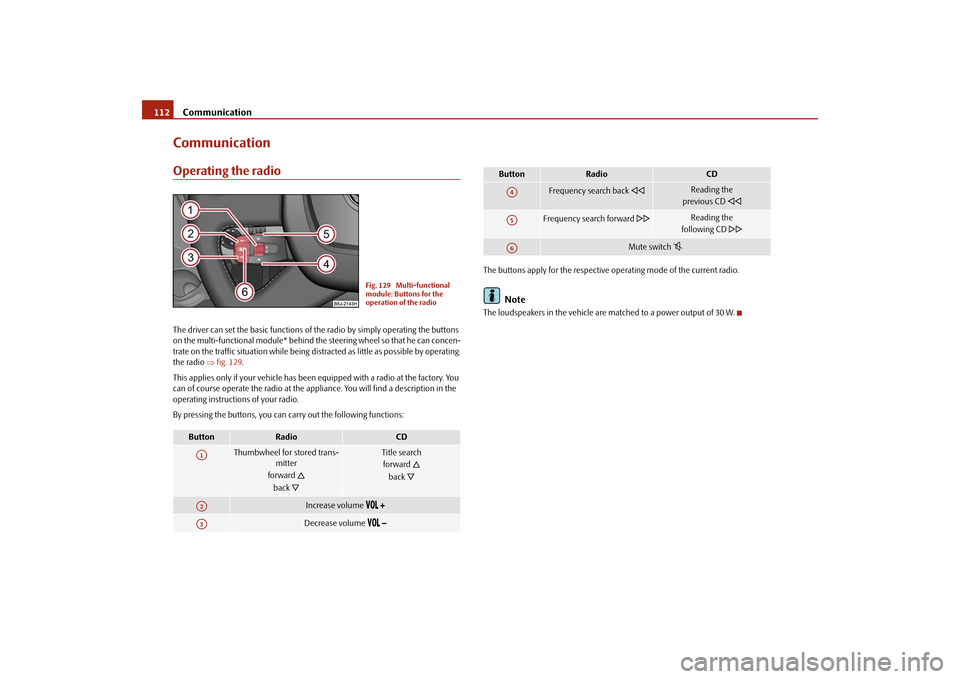
Communication 112CommunicationOperating the radioThe driver can set the basic functions of the radio by simply operating the buttons
on the multi-functional module* behind the steering wheel so that he can concen-
trate on the traffic situation while being distracted as little as possible by operating
the radio ⇒fig. 129.
This applies only if your vehicle has been equipped with a radio at the factory. You
can of course operate the radio at the appliance. You will find a description in the
operating instructions of your radio.
By pressing the buttons, you can carry out the following functions:The buttons apply for the respective operating mode of the current radio.
Note
The loudspeakers in the vehicle are matched to a power output of 30 W.
Button
Radio
CD
Thumbwheel for stored trans-
mitter
forward
back
Title search
forward
back
Increase volume
Decrease volume
Fig. 129 Multi-functional
module: Buttons for the
operation of the radio
A1A2A3
Frequency search back
Reading the
previous CD
Frequency search forward
Reading the
following CD
Mute switch
Button
Radio
CD
A4A5A6
s29g.4.book Page 112 Wednesday, June 17, 2009 9:54 AM
Page 114 of 263
Communication113
Using the system
Safety
Driving Tips
General Maintenance
Breakdown assistance
Praktik
Technical Data
Radio and mobile phone operation
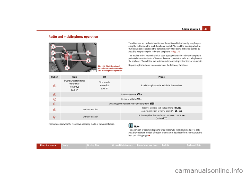
The driver can set the basic functions of the radio and telephone by simply oper-
ating the buttons on the multi-functional module* behind the steering wheel so
that he can concentrate on the traffic situation while being distracted as little as
possible by operating the radio and telephone ⇒fig. 130.
This applies only if your vehicle has been equipped with the radio and telephone
preinstallation at the factory. You can of course operate the radio and telephone at
the appliance. You will find a description in the operating instructions of your radio.
By pressing the buttons, you can carry out the following functions:
The buttons apply for the respective operating mode of the current radio.
Note
The operation of the mobile phone fitted with multi-functional module* is only
possible on certain models of mobile phone. More detailed information is available
by a specialist garage.
Fig. 130 Multi-functional
module: Buttons for the radio
and mobile phone operation
Button
Radio
CD
Phone
Thumbwheel for stored
transmitter
forward
back
Title search
forward
back
Scroll through with the aid of the thumbwheel
Increase volume
Decrease volume
Switching over between radio and telephone
without function
Receive, accept a call, call up menu PHONE,
confirm selection of menu point
/ /
without function
Activation/deactivation button for voice control
(button PTT)
A1A2A3A4A5A6
s29g.4.book Page 113 Wednesday, June 17, 2009 9:54 AM
Page 115 of 263
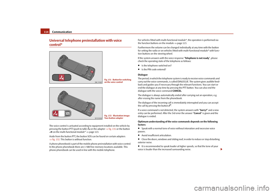
Communication 114Universal telephone preinstallation with voice control*The voice control is activated according to equipment installed on the vehicle by
pressing the button PTT (push to talk)
on the adapter ⇒fig. 131 or the button
on the multi-functional module* ⇒page 113.
Aside from the button PTT, the button SOS can be found on certain adapters
⇒fig. 132. This button is without function.
A phone phonebook is part of the mobile phone preinstallation with voice control.
In the phone phonebook there are 1 500 free memory locations available. This
phone phonebook can be used in line with the mobile telephone.For vehicles fitted with multi-functional module*, the operation is performed via
the function buttons on the module ⇒page 113.
Furthermore the volume can be changed individually at any time with the button
for setting the radio or on vehicles fitted with multi-functional module* with func-
tion buttons on the steering wheel.
If the system answers with the voice response “Telephone is not ready”, please
check the operating state of the telephone as follows:
•
Is the telephone switched on?
•
Is the PIN code entered?
Dialogue
The period, in which the telephone system is ready to receive voice commands and
carry out the voice commands, is called DIALOGUE. The system gives audible feed-
back and guides you if necessary through the relevant functions. You can start or
end the dialogue at any time by pressing the PTT button. You can also end the
dialogue with the voice command CANCEL.
The dialogue is always automatically ended after carrying out an operation, e.g.
after erasing the name from the phonebook.
The dialogue of the incoming call is immediately interrupted and you can accept
the call by pressing the button
.
If a voice command is not detected, the system answers with “Sorry?” and a new
entry can be performed. After the 3rd error the answer “Cancel” is given and the
dialogue is ended.
Optimum understanding of the voice commands depends on the following
factors:
•
Speak with a normal tone of voice without intonation and excessive voice
pauses.
•
Avoid insufficient articulation.
•
Close the doors, windows and sliding roof, in order to reduce or stop disturbing
exterior noise.
•
It is recommended to speak louder at higher speeds, so that the tone of your
voice is louder than the increased surrounding noise.
Fig. 131 Button for switching
on the voice controlFig. 132 Illustration image:
Two-button adapter
s29g.4.book Page 114 Wednesday, June 17, 2009 9:54 AM