warning light SKODA ROOMSTER 2010 1.G Service Manual
[x] Cancel search | Manufacturer: SKODA, Model Year: 2010, Model line: ROOMSTER, Model: SKODA ROOMSTER 2010 1.GPages: 231, PDF Size: 12.91 MB
Page 59 of 231
Seats and Storage
58
Adjust the angle of the seat backrest
– Relieve any pressure on the seat backrest (do not lean on it) and turn the hand-
wheel to adjust the angle of the backrest.
The driver's seat should be adjusted in such a way that the pedals can be fully pressed
to the floor with slightly bent legs.
The seat backrest on the driver's seat should be adjusted in such a way that the upper
point of the steering wheel can be easi ly reached with slightly bent arms.
WARNING
Only adjust the driver seat when the vehicle is stationary - risk of injury!
Take care when adjusting the seat! Adjusting the seat without care can lead
to bruises or injuries.
The seat backrests must not be angled too far back when driving otherwise
this will affect proper operation of the se at belts and of the airbag system - risk
of injury!
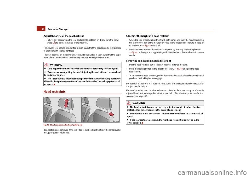
Head restraintsFig. 48 Head restraint: Adjusting / pulling outBest protection is achieved if the top edge of the head restraint is at the same level as
the upper part of your head.
Adjusting the height of a head restraint– Grasp the side of the head restraint with both hands and push the head restraint in the direction of axle of the metal guide rods, in the direction of arrow to the top or
to the bottom fig. 48 on the left.
– Move the head restraint downwards if required by pressing the locking button fig. 48 on the right and by pressing with the other hand the head restraint down-
wards.Removing and installing a head restraint– Pull the head restraint out of the seat backrest as far as the stop.
– Press the locking button in the direction of arrow fig. 48 and pull the head
restraint out.
– To re-insert the head restraint, push it do wn into the seat backrest far enough until
you hear the locking button engage.
The position of the front, rear outer head restraints and the rear middle head restraint*
is adjustable for height.
The head restraints must be adjusted to ma tch the size of the seat occupant. Correctly
adjusted head restraints together with the seat belts offer effective protection for the
occupants page 110.
WARNING
The head restraints must be correctly adjusted in order to offer effective
protection for the occupants in the event of an accident.
Do not drive under any circumstance with removed head restraints - risk of
injury!
If the rear seats are occupied, the rear head restraint must not be in the
lower position.
A3
s16g.4.book Page 58 Wednesda y, February 10, 2010 3:53 PM
Page 63 of 231
Seats and Storage
62Note
The seat belts of the outer seats must always be guided through the guide loops next
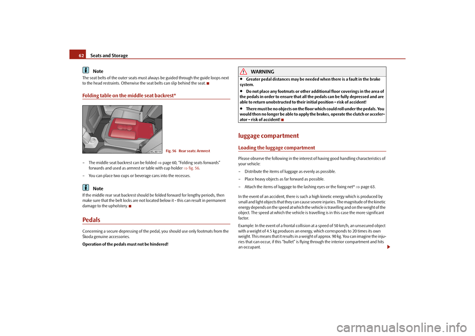
to the head restraints. Otherwise the seat belts can slip behind the seat.Folding table on the middle seat backrest*– The middle seat backrest can be folded page 60, “Folding seats forwards”
forwards and used as armres t or table with cup holder fig. 56 .
– You can place two cups or beverage cans into the recesses.
Note
If the middle rear seat backrest should be folded forward for lengthy periods, then
make sure that the belt locks are not located below it - this can result in permanent
damage to the upholstery.PedalsConcerning a secure depressing of the pedal, you should use only footmats from the
Škoda genuine accessories.
Operation of the pedals must not be hindered!
WARNING
Greater pedal distances may be needed when there is a fault in the brake
system.
Do not place any footmats or other additional floor coverings in the area of
the pedals in order to ensure that all the pedals can be fully depressed and are
able to return unobstructed to their initial position - risk of accident!
There must be no objects on the floor which could roll under the pedals. You
would then no longer be able to apply the brakes, operate the clutch or acceler-
ator - risk of accident!
luggage compartmentLoading the luggage compartmentPlease observe the following in the interest of having good handling characteristics of
your vehicle:
– Distribute the items of luggage as evenly as possible.
– Place heavy objects as far forward as possible.
– Attach the items of luggage to the lashing eyes or the fixing net* page 63.
In the event of an accident, there is such a high kinetic energy which is produced by
small and light objects that they can cause severe injuries. The magnitude of the kinetic
energy depends on the speed at which the vehicle is travelling and on the weight of the
object. The speed at which the vehicle is trave lling is in this case the more significant
factor.
Example: In the event of a frontal collision at a speed of 50 km/h, an unsecured object
with a weight of 4.5 kg produces an en ergy, which corresponds to 20 times its own
weight. This means that it results in a weight of approx. 90 kg. You can imagine the inju-
ries that can occur, if this “bullet” is fl ying through the interior compartment and hits
an occupant.
Fig. 56 Rear seats: Armrest
s16g.4.book Page 62 Wednesda y, February 10, 2010 3:53 PM
Page 64 of 231
Seats and Storage63
Using the system
Safety
Driving Tips
General Maintenance
Breakdown assistance
Praktik
Technical Data
WARNING
Stow the objects in the luggage compartment and attach them to the
lashing eyes.
Loose objects in the passenger compartment can be thrown forward during
a sudden manoeuvre or in case of an accident and can injure the occupants or
other oncoming traffic. This risk is still increased, if the objects which are flying
around are hit by a deployed airbag. In this case, the objects which are thrown
back can injure the occupants - hazard.
Please note that the handling properti es of your vehicle may be affected
when transporting heavy objects as a result of the displacement of the centre of
gravity. The speed and style of driv ing must be adjusted accordingly.
The items carried in the luggage compar tment should be stowed in such a
way that no objects are able to slip fo rward if there are any sudden driving or
braking manoeuvres undertaken - risk of injury!
When transporting fastened objects which are sharp and dangerous in the
luggage compartment enlarged by folding the rear seats forward or removing
the rear seats, ensure the safety of the passengers transported on the other rear
seats page 111, “Correct seated position fo r the occupants on the rear seats”.
If the rear seats next to the folded forward seat are occupied, ensure
maximum safety, e.g. by placing the goods to be transported in such a way that
a folding back of the seat is prev ented in case of a rear collision.
Never drive with the boot lid fully open ed or slightly ajar otherwise exhaust
gases may get into the interior of the vehicle - risk of poisoning!
On no account exceed the permissible axle loads and the permissible gross
weight of the vehicle - risk of accident!
Never transport occupants in the luggage compartment.Caution
Please ensure that the heating elements of the rear window heater are not damaged
as a result of objects sliding in this area.
Note
Tyre pressure must be adjusted to the load page 173, fig. 143.
The circulation of air in the vehicle help s to prevent the windows from misting up.
The used air streams out through the air venting slits which are located under the
bumper in the luggage compartment. Check fo r yourself that the air venting slits are
not covered.
Vehicles of category N1On vehicles of the category N1, which are no t fitted with a protective grille, a lashing
set which complies with the standard EN 12195 (1 - 4) must be used for fastening the
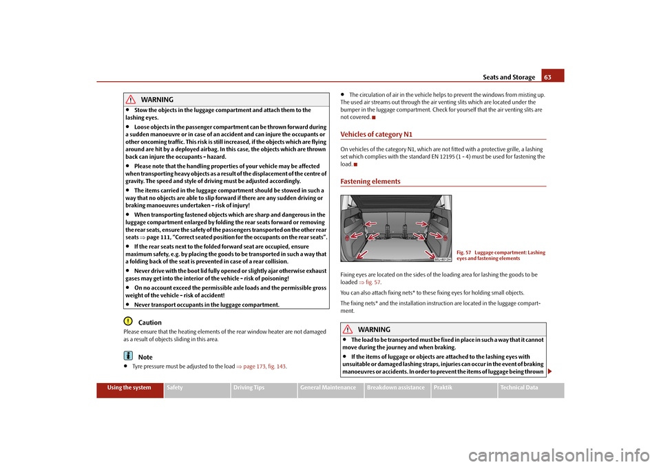
load.Fastening elementsFixing eyes are located on th e sides of the loading area for lashing the goods to be
loaded fig. 57 .
You can also attach fixing nets* to these fixing eyes for holding small objects.
The fixing nets* and the installation inst ruction are located in the luggage compart-
ment.
WARNING
The load to be transported must be fixed in place in such a way that it cannot
move during the journey and when braking.
If the items of luggage or objects are attached to the lashing eyes with
unsuitable or damaged lashing straps, inju ries can occur in the event of braking
manoeuvres or accidents. In order to prevent the items of luggage being thrown
Fig. 57 Luggage compartment: Lashing
eyes and fastening elements
s16g.4.book Page 63 Wednesday, February 10, 2010 3:53 PM
Page 66 of 231
Seats and Storage65
Using the system
Safety
Driving Tips
General Maintenance
Breakdown assistance
Praktik
Technical Data
The luggage compartment cover
You can use the luggage compartment cover behind the head
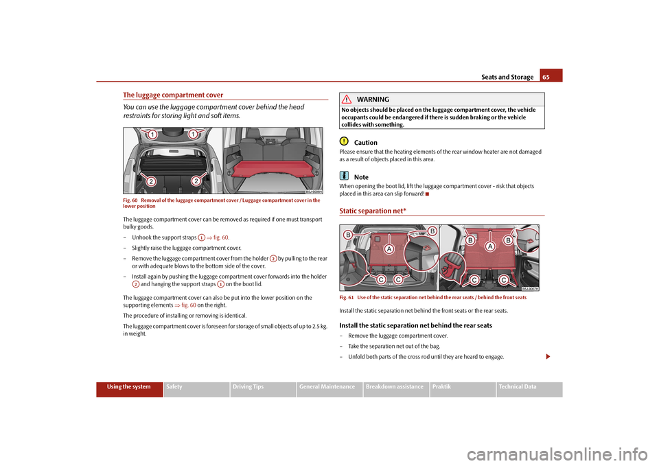
restraints for storing light and soft items.Fig. 60 Removal of the luggage compartmen t cover / Luggage compartment cover in the
lower positionThe luggage compartment cover can be removed as required if one must transport
bulky goods.
– Unhook the support straps fig. 60 .
– Slightly raise the luggage compartment cover.
– Remove the luggage compartment cover from the holder by pulling to the rear or with adequate blows to th e bottom side of the cover.
– Install again by pushing the luggage compartment cover forwards into the holder and hanging the support straps on the boot lid.
The luggage compartment cover can also be put into the lower position on the
supporting elements fig. 60 on the right.
The procedure of installing or removing is identical.
The luggage compartment cover is foreseen for storage of small objects of up to 2.5 kg.
in weight.
WARNING
No objects should be placed on the luggage compartment cover, the vehicle
occupants could be endangered if th ere is sudden braking or the vehicle
collides with something.
Caution
Please ensure that the heating elements of the rear window heater are not damaged
as a result of objects placed in this area.
Note
When opening the boot lid, lift the luggage compartment cover - risk that objects
placed in this area can slip forward!Static separation net*Fig. 61 Use of the static separation net be hind the rear seats / behind the front seatsInstall the static separation net behind the front seats or the rear seats.Install the static separation net behind the rear seats– Remove the luggage compartment cover.
– Take the separation net out of the bag.
– Unfold both parts of the cross rod until they are heard to engage.
A1
A2
A2
A1
s16g.4.book Page 65 Wednesday, February 10, 2010 3:53 PM
Page 69 of 231
Seats and Storage
68
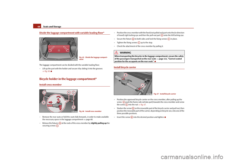
Divide the luggage compartment with variable loading floor*The luggage compartment can be divided with the variable loading floor.
– Lift up the part with the holder and secure it by sliding it into the grooves
fig. 65 .Bicycle holder in the luggage compartment*Install cross member– Remove the rear seats or fold the seats fully forwards, in order to make available
the necessary space in the luggage compartment page 60.
– Release the fixtures at the ends of the cross member by slightly pulling up the
securing screws . – Position the cross member with the fixed (not
pulled out) part onto the (in direction
of travel) right lashing eye and then the pull-out part onto the left lashing eye.
– Secure the fixture to both sides an d lock the fixing screws in place.
– Tighten the fixing screws up to the stop.
– Check the attachment of the cross member by pulling it.
WARNING
When transporting the bicycles in the luggage compartment, ensure the safety
of the passengers transported on the rear seats page 111, “Correct seated
position for the occupants on the rear seats”.Install bicycle carrier– Position the approved bicycle carrier on the cross member, after pulling up the
screw push the frame side rail (alu-part) towards the cross member and screw
the screw into the nut fig. 67 .
– Slacken the screw on the moveable part of the bicycle carrier and pull out, then
position the moveable part of the carrier, depending on bicycle size, into one of the
three possible positions.
– Insert the screw into the desired position and tighten.
Fig. 65 Divide the luggage compart-
mentFig. 66 Install cross member
AB
AC
AA
AB
AC
AC
Fig. 67 Install bicycle carrier
AAAA
ABAB
s16g.4.book Page 68 Wednesda y, February 10, 2010 3:53 PM
Page 73 of 231
Seats and Storage
72
Parking ticket holderThe note holder is designed e.g. for atta ching a car park ticket in parking areas.
The parking ticket has to always be removed before starting off in order not to restrict
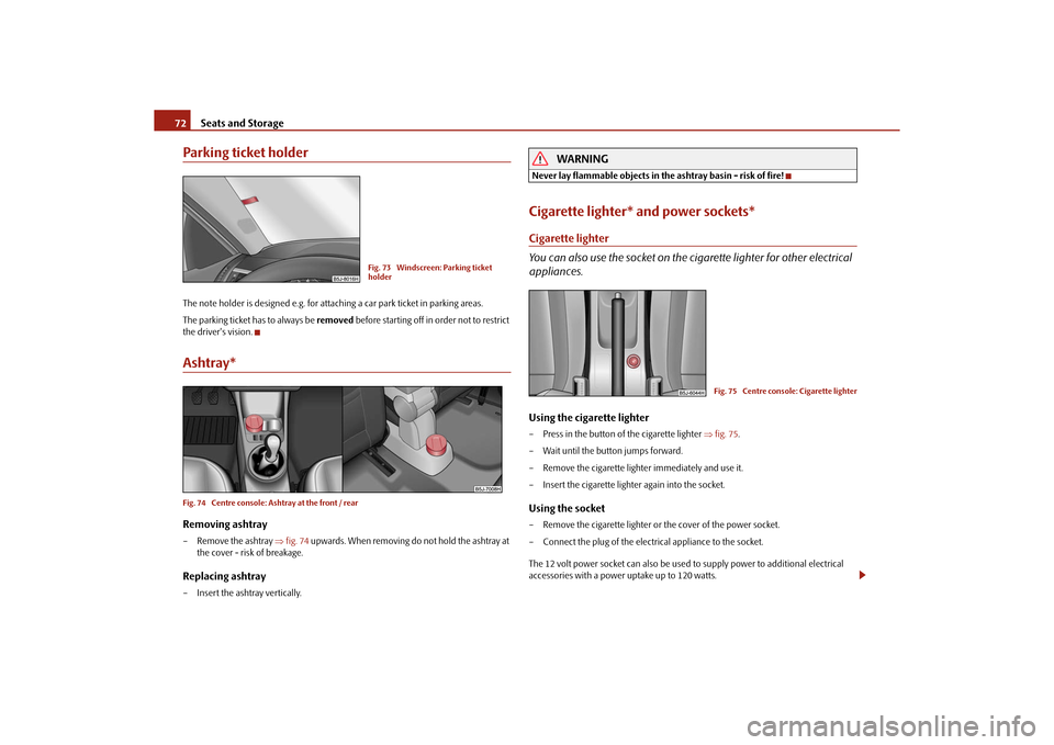
the driver's vision.Ashtray*Fig. 74 Centre console: Ashtray at the front / rearRemoving ashtray– Remove the ashtray fig. 74 upwards. When removing do not hold the ashtray at
the cover - risk of breakage.Replacing ashtray– Insert the ashtray vertically.
WARNING
Never lay flammable objects in the ashtray basin - risk of fire!Cigarette lighter* and power sockets*Cigarette lighter
You can also use the socket on the ci garette lighter for other electrical
appliances.Using the cigarette lighter– Press in the button of the cigarette lighter fig. 75 .
– Wait until the button jumps forward.
– Remove the cigarette lighter immediately and use it.
– Insert the cigarette lighter again into the socket.Using the socket– Remove the cigarette lighter or the cover of the power socket.
– Connect the plug of the electrical appliance to the socket.
The 12 volt power socket can also be used to supply power to additional electrical
accessories with a power uptake up to 120 watts.
Fig. 73 Windscreen: Parking ticket
holder
Fig. 75 Centre console: Cigarette lighter
s16g.4.book Page 72 Wednesda y, February 10, 2010 3:53 PM
Page 74 of 231
Seats and Storage73
Using the system
Safety
Driving Tips
General Maintenance
Breakdown assistance
Praktik
Technical Data
WARNING
Take care when using the cigarette ligh ter! Not paying proper attention or
incorrect use the cigarette lighter in an uncontrolled manner may result in
burns.
The cigarette lighter and the power socket also operates when the ignition is
switched off or the ignition key withdrawn. This is why you should never leave
children unattended in the vehicle!Caution
Always use matching plugs to avoid damagi ng the power socket.
Note
Connecting electrical components when the engine is not running will drain
the battery of the vehicle - risk of battery draining!
Further information page 179.
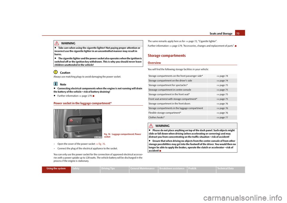
Power socket in the luggage compartment*– Open the cover of the power socket fig. 76 .
– Connect the plug of the electrical appliance to the socket.
You can only use the power socket for the connection of approved electrical accesso-
ries with a power uptake up to 120 watts. The vehicle battery will be discharged in the
process if the engine is stationary. The same remarks apply here as for
page 72, “Cigarette lighter”.
Further information page 179, “Accessories, changes and replacement of parts”.
Storage compartmentsOverviewYou will find the following storag e facilities in your vehicle:
WARNING
Please do not place anything on top of the dash panel. Such objects might
slide or fall down when driving (whe n accelerating or cornering) and may
distract you from concentrating on the traffic situation - risk of accident!
Ensure that when driving no objects from the centre console of from other
storage possibilities may get into the fo otwell of the driver. You would then no
longer be able to apply the brakes, oper ate the clutch or accelerator - risk of
accident!
Fig. 76 Luggage compartment: Power
socket
Storage compartments on the front passenger side*
page 74
Storage compartment on the driver's side
page 74
Storage compartment for spectacles*
page 75
Stowage compartment in centre console
page 75
Storage compartment in the front seat*
page 75
Front seat armrest with storage compartment*
page 75
Storage compartment in the front doors
page 76
Storage compartments in the luggage compartment
page 76
Flexible storage compartment*
page 76
Clothes hooks*
page 77
s16g.4.book Page 73 Wednesda y, February 10, 2010 3:53 PM
Page 78 of 231
Seats and Storage77
Using the system
Safety
Driving Tips
General Maintenance
Breakdown assistance
Praktik
Technical Data
– Press the upper corners to the inside
and release the storage compartment by
pulling upwards.
– Take it out by pulling toward s the middle of the vehicle.
Installing– Insert both ends of the flexible storage compartment into the openings of the right
side trim panel of the luggage compartment and push it downwards until it locks.Clothes hooks*The clothes hooks are located on the handle of the headliner above each of the rear
doors.
WARNING
Ensure that any clothes hanging from the hooks do not impair your vision to
the rear.
Use the hooks for hanging only light item s of clothing and ensure that there
are no heavy or sharp-edge d objects in the pockets.
The maximum permissable load of the hooks is 2 kg.
Do not use clothes hangers for hanging up items of clothing otherwise this
will interfere with the protection offered by the head airbag*.
s16g.4.book Page 77 Wednesda y, February 10, 2010 3:53 PM
Page 79 of 231
Heating and air conditioning system
78
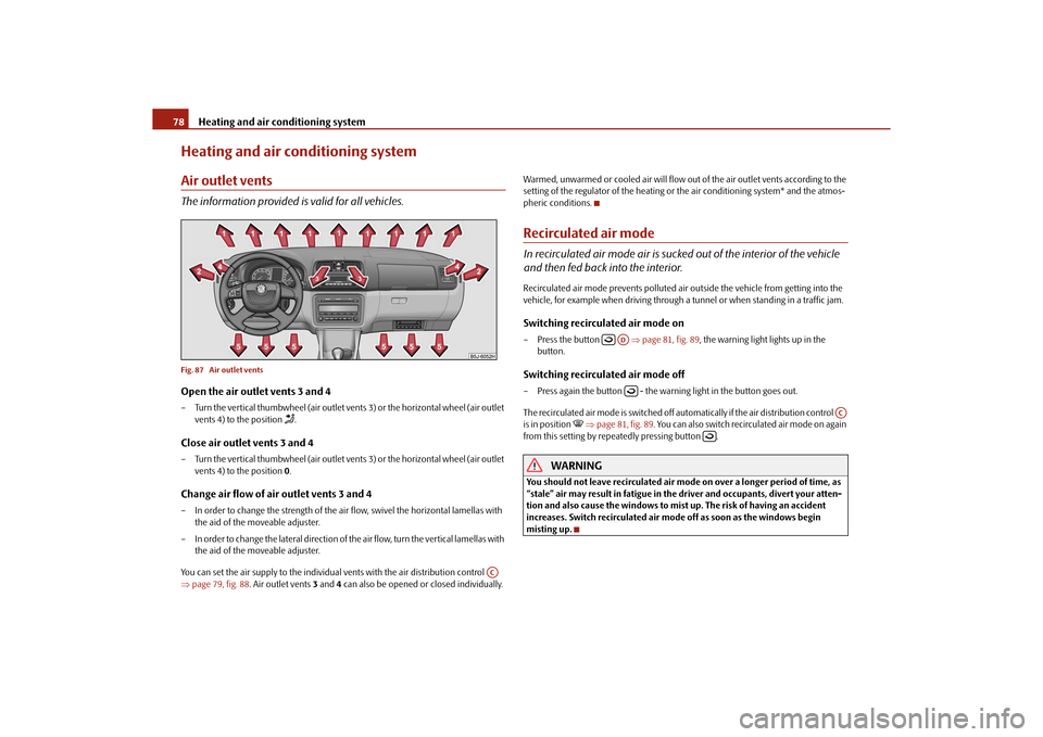
Heating and air conditioning systemAir outlet ventsThe information provided is valid for all vehicles.Fig. 87 Air outlet ventsOpen the air outlet vents 3 and 4– Turn the vertical thumbwheel (air outlet vents 3) or the horizontal wheel (air outlet
vents 4) to the position
.
Close air outlet vents 3 and 4– Turn the vertical thumbwheel (air outlet vents 3) or the horizontal wheel (air outlet
vents 4) to the position 0.Change air flow of air outlet vents 3 and 4– In order to change the strength of the ai r flow, swivel the horizontal lamellas with
the aid of the moveable adjuster.
– In order to change the lateral direction of the air flow, turn the vertical lamellas with the aid of the moveable adjuster.
You can set the air supply to the individual vents with the air distribution control
page 79, fig. 88 . Air outlet vents 3 and 4 can also be opened or closed individually. Warmed, unwarmed or cooled air will flow out of the air outlet vents according to the
setting of the regulator of the heating or the air conditioning system* and the atmos-
pheric conditions.
Recirculated air modeIn recirculated air mode air is sucked out of the interior of the vehicle
and then fed back into the interior.Recirculated air mode prevents polluted air outside the vehicle from getting into the
vehicle, for example when driving through a tunnel or when standi
ng in a traffic jam.Switching recirculated air mode on– Press the button page 81, fig. 89 , the warning light lights up in the
button.Switching recirculated air mode off– Press again the button - the warning light in the button goes out.
The recirculated air mode is switched off automatically if the air distribution control
is in position
page 81, fig. 89. You can also switch recirc ulated air mode on again
from this setting by repe atedly pressing button .
WARNING
You should not leave recirculated air mode on over a longer period of time, as
“stale” air may result in fatigue in the driver and occupants, divert your atten-
tion and also cause the windows to mist up. The risk of having an accident
increases. Switch recirculated air mo de off as soon as the windows begin
misting up.
AC
AD
AC
s16g.4.book Page 78 Wednesda y, February 10, 2010 3:53 PM
Page 83 of 231
Heating and air conditioning system
82
Setting temperature
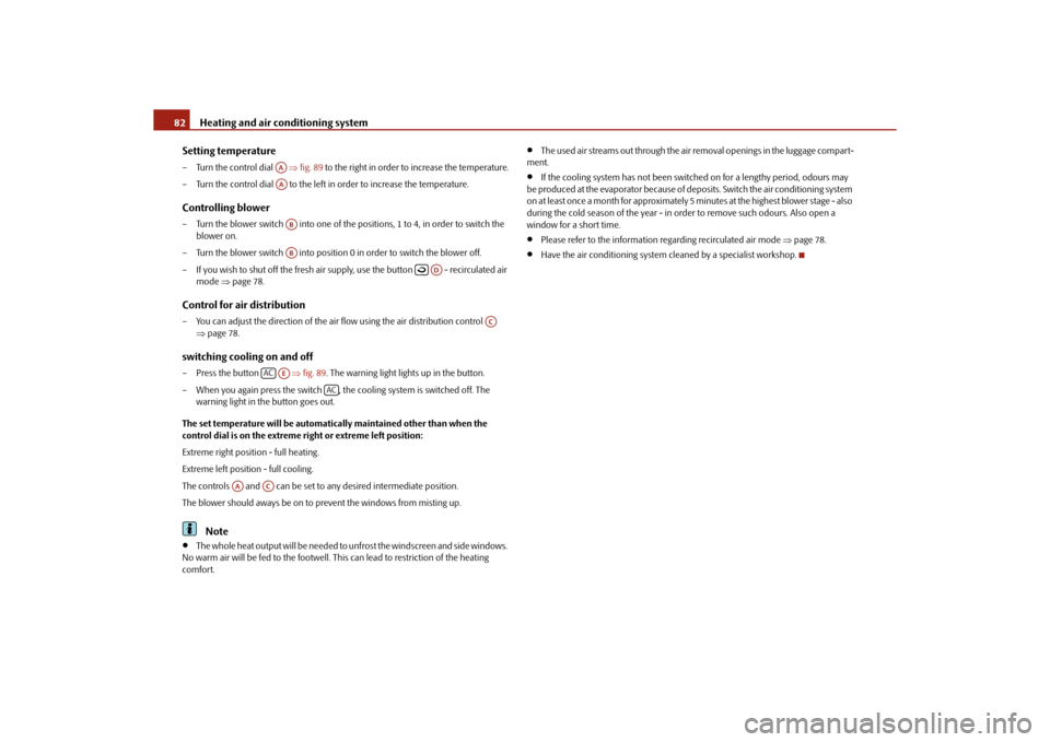
– Turn the control dial fig. 89 to the right in order to increase the temperature.
– Turn the control dial to the left in order to increase the temperature.Controlling blower– Turn the blower switch into one of the po sitions, 1 to 4, in order to switch the
blower on.
– Turn the blower switch into position 0 in order to switch the blower off.
– If you wish to shut off the fresh air supp ly, use the button - recirculated air
mode page 78.Control for air distribution– You can adjust the direction of the air flow using the air distribution control
page 78.switching cooling on and off– Press the button fig. 89 . The warning light lights up in the button.
– When you again press the switch , the cooling system is switched off. The warning light in the button goes out.
The set temperature will be automatically maintained other than when the
control dial is on the extreme right or extreme left position:
Extreme right position - full heating.
Extreme left position - full cooling.
The controls and can be set to any desired intermediate position.
The blower should aways be on to prevent the windows from misting up.
Note
The whole heat output will be needed to unfrost the windscreen and side windows.
No warm air will be fed to the footwell. This can lead to restriction of the heating
comfort.
The used air streams out through the air removal openings in the luggage compart-
ment.
If the cooling system has not been switched on for a lengthy period, odours may
be produced at the evaporator because of de posits. Switch the air conditioning system
on at least once a month for approximately 5 minutes at the highest blower stage - also
during the cold season of the year - in order to remove such odours. Also open a
window for a short time.
Please refer to the information regarding recirculated air mode page 78.
Have the air conditioning system cleaned by a specialist workshop.
AAAAABAB
AD
AC
AC
AE
AC
AA
AC
s16g.4.book Page 82 Wednesda y, February 10, 2010 3:53 PM