navigation system SKODA ROOMSTER 2012 1.G User Guide
[x] Cancel search | Manufacturer: SKODA, Model Year: 2012, Model line: ROOMSTER, Model: SKODA ROOMSTER 2012 1.GPages: 194, PDF Size: 4.8 MB
Page 148 of 194

Charging a vehicle battery
First read and observe the introductory information and safety warn-
ings on page 143.
A properly charged vehicle battery is essential for reliably starting the engine.
›
Switch off the ignition and all of the electrical components.
› Only for “quick-charging”: Disconnect both battery cables (first of all “negative”,
then “positive”).
› Attach the terminal clamps of the charger to the battery terminals (red =
“posi-
tive
”, black = “negative”).
› Only now plug the mains cable of the charger into the power socket and switch
on the device.
› When charging is completed: Switch off the charger and remove the mains ca-
ble from the power socket.
› Only then disconnect the charger's terminal clamps.
› Reconnect the cables to the battery, if necessary (first of all
“positive”, then
“negative
”).
It is not normally necessary to disconnect the cables of the battery if you re-
charge the vehicle battery using low amperages (as for example from a mini-
charger). Refer to the instructions of the charger manufacturer.
A charging current of 0.1 multiple of the total vehicle battery capacity (or lower)
must be used until full charging is achieved.
It is, however, necessary to disconnect both cables before charging the battery
with high amperages, so-called “ quick-charging”.
“Quick-charging” the vehicle battery is dangerous and requires a special charger
and specialist knowledge. We therefore recommend having the quick charging of
vehicle batteries undertaken by a ŠKODA specialist garage.
The vent plugs of the vehicle battery should not be opened for charging. CAUTION
On vehicles with the START/STOP system, the pole terminal of the charger must
not be connected directly to the negative terminal of the vehicle battery, but only
to the engine earth » page 164, Jump-starting in vehicles with the
START-STOP
system . Ð
ä Disconnecting and reconnecting the vehicle battery
First read and observe the introductory information and safety warn-
ings on page 143.
On disconnecting and reconnecting the vehicle battery the following functions
are initially deactivated or are no longer able to operate fault-free:
Operation Operating measure
Electrical power window (operational faults) » page 35
Enter the radio/navigation system code num-
ber » User manual of the radio
or » user manual of the naviga-
tion system
Setting the clock » page 11
Data in the multifunction display are deleted. » page 12 Note
We recommend having the vehicle checked by a ŠKODA Service Partner to ensure
the full functionality of all electrical systems. Ð Replacing the vehicle battery
First read and observe the introductory information and safety warn-
ings on page 143.
When replacing a battery, the new vehicle battery must have the same capacity,
voltage, amperage and be the same size. Suitable types of vehicle batteries can
be purchased from a
ŠKODA Service Partner.
We recommend that the battery is replaced by a ŠKODA Service Partner, where
the new vehicle battery will be installed properly and the original battery will be
disposed of in accordance with national regulations. Ð
ä
ä
146 General Maintenance
Page 169 of 194

Fuses in the dash panel
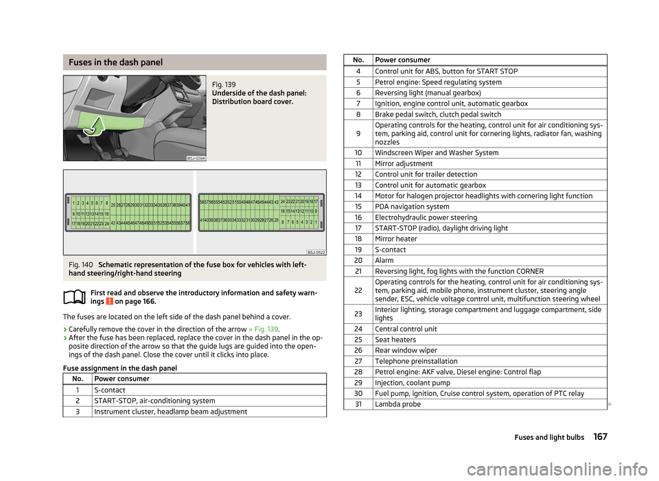
Fig. 139
Underside of the dash panel:
Distribution board cover. Fig. 140
Schematic representation of the fuse box for vehicles with left-
hand steering/right-hand steering
First read and observe the introductory information and safety warn-
ings on page 166.
The fuses are located on the left side of the dash panel behind a cover.
›
Carefully remove the cover in the direction of the arrow
» Fig. 139.
› After the fuse has been replaced, replace the cover in the dash panel in the op-
posite direction of the arrow so that the guide lugs are guided into the open-
ings of the dash panel. Close the cover until it clicks into place.
Fuse assignment in the dash panel No. Power consumer
1 S-contact
2 START-STOP, air-conditioning system
3 Instrument cluster, headlamp beam adjustment ä No. Power consumer
4 Control unit for ABS, button for START STOP5 Petrol engine: Speed regulating system
6 Reversing light (manual gearbox) 7 Ignition, engine control unit, automatic gearbox
8 Brake pedal switch, clutch pedal switch
9 Operating controls for the heating, control unit for air conditioning sys-
tem, parking aid, control unit for cornering lights, radiator fan, washing
nozzles
10 Windscreen Wiper and Washer System 11 Mirror adjustment
12 Control unit for trailer detection
13 Control unit for automatic gearbox
14 Motor for halogen projector headlights with cornering light function 15 PDA navigation system
16 Electrohydraulic power steering 17 START-STOP (radio), daylight driving light
18 Mirror heater 19 S-contact
20 Alarm 21 Reversing light, fog lights with the function CORNER
22 Operating controls for the heating, control unit for air conditioning sys-
tem, parking aid, mobile phone, instrument cluster, steering angle
sender, ESC, vehicle voltage control unit, multifunction steering wheel
23 Interior lighting, storage compartment and luggage compartment, side
lights
24 Central control unit 25 Seat heaters
26 Rear window wiper 27 Telephone preinstallation
28 Petrol engine: AKF valve, Diesel engine: Control flap 29 Injection, coolant pump
30 Fuel pump, ignition, Cruise control system, operation of PTC relay 31 Lambda probe £ 167
Fuses and light bulbs