Rear seat SKODA ROOMSTER 2012 1.G Owner's Manual
[x] Cancel search | Manufacturer: SKODA, Model Year: 2012, Model line: ROOMSTER, Model: SKODA ROOMSTER 2012 1.GPages: 194, PDF Size: 4.8 MB
Page 5 of 194
Table of Contents
Abbreviations
Using the system
Cockpit 7
Overview 6
Instruments and Indicator Lights 8
Instrument cluster 8
Multifunction display (onboard computer) 12
MAXI DOT (information display) 15
Warning lights 17
Unlocking and locking 25
Vehicle key 25
Locking/unlocking the vehicle without central
locking 26
Central locking system 27
Remote control 29
Anti-theft alarm system 30
Interior monitor and towing protection 31
Emergency locking of the doors 31
Boot lid 32
Electrical power windows 33
Panorama roof 35
Lights and visibility 36
Lights 36
Interior light 41
Visibility 42
Windscreen wipers and washers 42
Rear window 45
Seats and Stowage 47
Front seats 47
Head restraints 48
Rear seats 49Boot 51
Variable loading floor in the boot 55
Bicycle carrier in the luggage compartment 56
Roof rack system 58
Cup holders 59
Ashtray 60
Cigarette lighter, 12-volt power socket 60
Storage compartments 61
Clothes hooks 65
Parking ticket holder 66
Heating and air conditioning system 67
Heating and air conditioning system 67
Air outlet vents 68
Heating 68
Air conditioning system (manual air conditioning
system) 70
Climatronic (automatic air conditioning
system) 73
Starting-off and Driving 76
Starting and stopping the engine 76
Brakes and brake assist systems 78
Shifting (manual gearbox) 82
pedals 82
Parking aid 82
Cruise control system (CCS) 83
START/STOP 85
Automatic gearbox 87
Automatic gearbox 87
Communication 92
Mobile phones and two-way radio systems 92
Universal telephone preinstallation GSM II 92
Voice control 96
Multimedia 97 Safety
Passive Safety 100
General information 100
Correct seated position 101
Seat belts 104
Seat belts 104
Airbag system 109
Description of the airbag system 109
Front airbags 110
Side airbags 111
Head airbags 112
Deactivating airbags 113
Transporting children safely 115
Child seat 115
Driving Tips
Driving and the Environment 119
The first 1 500 km 119
Catalytic converter 119
Economical and environmentally friendly
driving 120
Environmental compatibility 122
Driving abroad 123
Avoiding damage to your vehicle 123
Driving through water on the street 124
Towing a trailer 125
Towing a trailer 125
General Maintenance
Taking care of and cleaning the vehicle 127
Taking care of your vehicle 127
3
Table of Contents
Page 6 of 194
Inspecting and replenishing 134
Fuel 134
Engine compartment 136
Vehicle battery 143
Wheels and Tyres 148
Tyres 148
Accessories, changes and replacement of parts 155
Introductory information 155
Changes and impairments of the airbag
system 155
Do-it-yourself
Do-it-yourself 156
First-aid kit and warning triangle 156
Fire extinguisher 156
Vehicle tool kit 156
Changing a wheel 157
Breakdown kit 160
Jump-starting 163
Towing the vehicle 164
Fuses and light bulbs 166
Fuses 166
Bulbs 169
Praktik
Praktik 174
Rear interior light 174
Lashing eyes 174
Adjustable safety partition behind the front
seats 174
Fixing of the loading floor 175
Adjustment of the safety partition 175
Emergency unlocking of the loading area door 175 Technical data
Technical data 176
Introductory information 176
Data on the vehicle sticker and the type plate 176
Dimensions 178
Specifications and engine oil capacity 179
Vehicle-specific details per engine type 180
Index
4 Table of Contents
Page 9 of 194
Using the system
Cockpit
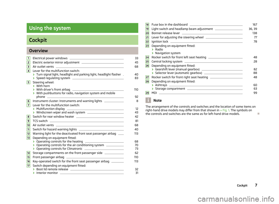
Overview
Electrical power windows 33
Electric exterior mirror adjustment 45
Air outlet vents 68
Lever for the multifunction switch:
› Turn signal light, headlight and parking light, headlight flasher 40
› Speed regulating system 83
Steering wheel:
› With horn
› With driver’s front airbag 110
› With pushbuttons for radio, navigation system and mobile
phone 92
Instrument cluster: Instruments and warning lights 8
Lever for the multifunction switch:
› Multifunction display 12
› Windscreen wiper and wash system 43
Switch for rear window heater 42
TCS switch 81
Air outlet vents 68
Switch for hazard warning lights 40
Warning light for the deactivated front seat passenger airbag 113
Depending on equipment fitted:
› Operating controls for the heating 68
› Operating controls for the air conditioning system 70
› Operating controls for Climatronic 73
Storage compartments on the front passenger side 62
Front passenger airbag 110
Key-operated switch for the front seat passenger airbag 113
Switch depending on equipment fitted:
› Boot lid remote release 32
› Interior monitor 311
2
3
4
5
6
7
8
9
10
11
12
13
14
15
16
17 Fuse box in the dashboard 167
Light switch and headlamp beam adjustment 36, 39
Bonnet release lever 138
Lever for adjusting the steering wheel 77
Ignition lock 78
Depending on equipment fitted:
› Radio
› Navigation system
Rocker switch for front left seat heating 48
Central locking system 28
Depending on equipment fitted:
› Gearshift lever (manual gearbox) 82
› Selector lever (automatic gearbox) 88
Rocker switch for front right seat heating 48
Depending on equipment fitted:
› Ashtrays 60
› Storage compartment 63
MDI 99
Note
The arrangement of the controls and switches and the location of some items on
right-hand drive models may differ from that shown in »
Fig. 1. The symbols on
the controls and switches are the same as for left-hand drive models. Ð 18
19
20
21
22
23
24
25
26
27
28
29
7
Cockpit
Page 19 of 194
WARNING
If you have to stop for technical reasons, then park the vehicle at a safe dis-
tance from the traffic, switch off the engine and activate the hazard warning
light system » page 40. Note
■ If warning messages are shown in the information display, you need to confirm
these messages with the button B
» Fig. 7
on page 15 in order to call up the main
menu.
■ As long as the operational faults are not rectified, the symbols are always indi-
cated again. After they are displayed for the first time, the symbols continue to be
indicated without any extra messages for the driver. ÐWarning lights
Overview
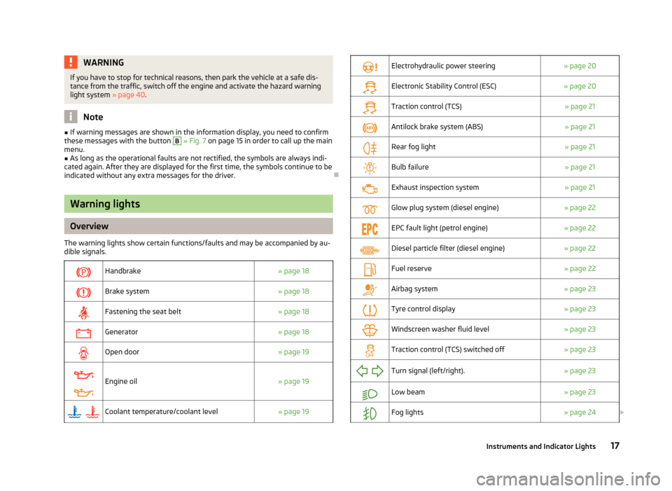
The warning lights show certain functions/faults and may be accompanied by au-
dible signals.
Handbrake
» page 18
Brake system
» page 18
Fastening the seat belt
» page 18
Generator
» page 18
Open door
» page 19
Engine oil
» page 19
Coolant temperature/coolant level
» page 19
Electrohydraulic power steering
» page 20
Electronic Stability Control (ESC)
» page 20
Traction control (TCS)
» page 21
Antilock brake system (ABS)
» page 21
Rear fog light
» page 21
Bulb failure
» page 21
Exhaust inspection system
» page 21
Glow plug system (diesel engine)
» page 22
EPC fault light (petrol engine)
» page 22
Diesel particle filter (diesel engine)
» page 22
Fuel reserve
» page 22
Airbag system
» page 23
Tyre control display
» page 23
Windscreen washer fluid level
» page 23
Traction control (TCS) switched off
» page 23
Turn signal (left/right).
» page 23
Low beam
» page 23
Fog lights
» page 24£ 17
Instruments and Indicator Lights
Page 35 of 194
The delayed automatic locking function of the boot lid can be activated on your
vehicle. The following applies following activation of this function: If the boot lid
was locked with the button
on the remote control key 2
» page 29, then it is
possible to open the lid within a limited period of it being closed.
If you wish, a
ŠKODA Service Partner can activate or deactivate the delayed auto-
matic locking of the boot lid. The Service Partner will also provide any further in-
formation that is required.
There is a risk of unwanted entry into the vehicle before the boot lid is locked au-
tomatically. Always lock the vehicle using the button on the remote control or
with the key if no remote control is available » page 28 .ÐEmergency unlocking
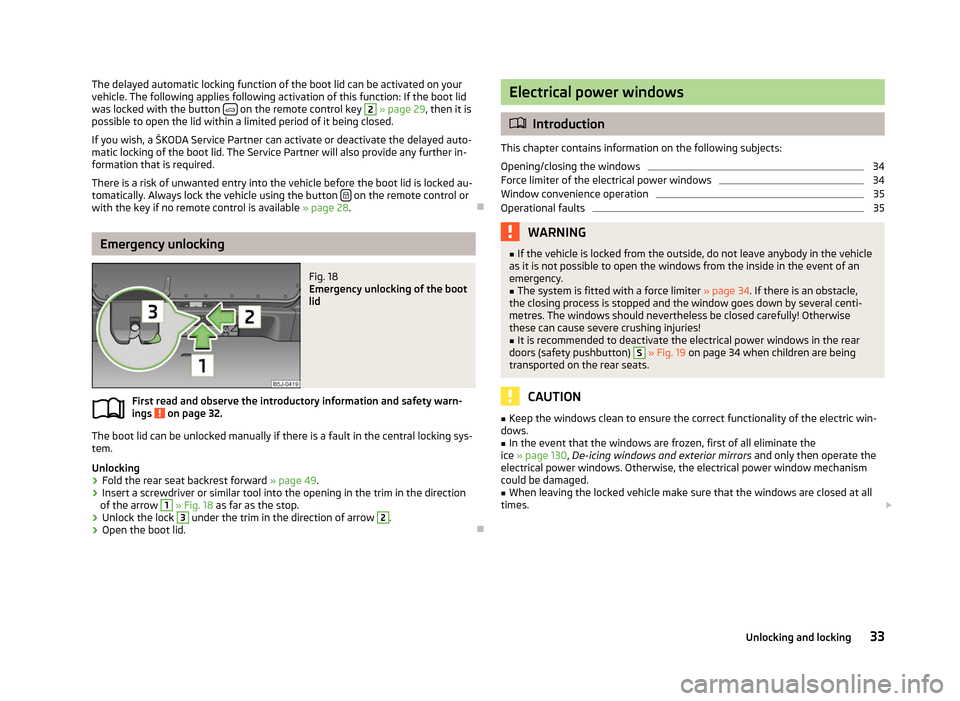
Fig. 18
Emergency unlocking of the boot
lid
First read and observe the introductory information and safety warn-
ings on page 32.
The boot lid can be unlocked manually if there is a fault in the central locking sys-
tem.
Unlocking
›
Fold the rear seat backrest forward
» page 49.
› Insert a screwdriver or similar tool into the opening in the trim in the direction
of the arrow 1
» Fig. 18 as far as the stop.
› Unlock the lock 3
under the trim in the direction of arrow 2
.
› Open the boot lid. Ð
ä Electrical power windows
ä
Introduction
This chapter contains information on the following subjects:
Opening/closing the windows 34
Force limiter of the electrical power windows 34
Window convenience operation 35
Operational faults 35
WARNING
■ If the vehicle is locked from the outside, do not leave anybody in the vehicle
as it is not possible to open the windows from the inside in the event of an
emergency.
■ The system is fitted with a force limiter » page 34. If there is an obstacle,
the closing process is stopped and the window goes down by several centi-
metres. The windows should nevertheless be closed carefully! Otherwise
these can cause severe crushing injuries!
■ It is recommended to deactivate the electrical power windows in the rear
doors (safety pushbutton) S
» Fig. 19 on page 34 when children are being
transported on the rear seats. CAUTION
■ Keep the windows clean to ensure the correct functionality of the electric win-
dows. ■ In the event that the windows are frozen, first of all eliminate the
ice » page 130, De-icing windows and exterior mirrors and only then operate the
electrical power windows. Otherwise, the electrical power window mechanism
could be damaged. ■ When leaving the locked vehicle make sure that the windows are closed at all
times. £
33
Unlocking and locking
Page 41 of 194
The fog lights with the function CORNER are adjusted according to the steering
angle or after switching on the turn signal light
1)
in the following circumstances:
› the vehicle is stationary and the engine is running or it moves with a speed of
maximum 40 km/h;
› the daytime running lights are not switched on;
› the low beam is switched on;
› the fog lights are not switched on;
› no reverse gear is engaged. ÐRear fog light
First read and observe the introductory information and safety warn-
ings on page 36.
Switching on
› First of all, turn the light switch
» Fig. 22 on page 38 » page 38 to position or
.
› Pull the light switch to position 2
.
If the vehicle is not fitted with fog lights » page 38, the rear fog light is switched
on by turning the light switch to the position or and is pulled out directly to
the position 2
. This switch does not have two positions, but only one position.
The warning light
lights up in the instrument cluster when the rear fog light is
switched on » page 17.
Only the rear fog light on the trailer lights up if the vehicle has a factory-fitted
towing device or a towing device from ŠKODA original accessories and it is driven
with a trailer and the rear fog light switched on. Ð
ä Headlight beam adjustment
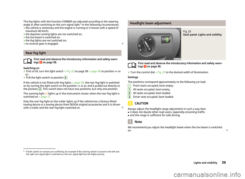
Fig. 23
Dash panel: Lights and visibility
First read and observe the introductory information and safety warn-
ings on page 36.
›
Turn the control dial
» Fig. 23 to the desired width of illumination.
Settings
The positions correspond approximately to the following car load. Front seats occupied, boot empty.
All seats occupied, boot empty.
All seats occupied, boot loaded.
Driver seat occupied, boot loaded. CAUTION
Always adjust the headlight range adjustment in such a way that:
■ it does not dazzle other road users, especially oncoming traffic;
■ and the range is sufficient for safe driving. Note
We recommend you adjust the headlight beam when the low beam is switched
on. Ð
ä -
1
2
3
1)
If both switch on versions are conflicting, for example if the steering wheel is turned to the left and
the right turn signal light is switched on, the turn signal light has the higher priority.
39
Lights and visibility
Page 47 of 194
›
With the other hand unlock the locking button A
in the direction of arrow and
remove the wiper blade.
Attaching the wiper blade
› Position the wiper blade onto the wiper arm and lock the locking but-
ton A
» Fig. 32
.
› Check that the wiper blade is correctly attached.
› Fold the wiper arm back to the windscreen. ÐRear window
Manual dimming interior mirror
Basic setting
› Pull the lever on the bottom edge of the mirror forward.
Dimming mirror
› Push the lever on the bottom edge of the mirror backwards. ÐAdditional rear-view mirror
Fig. 33
Additional interior mirror
The additional interior mirror allows the driver a wider field of view of the rear
seats.
Adjusting the angle › Adjust the mirror in direction of arrow to the desired position. WARNING
Concentrate fully at all times on your driving! As the driver you are fully re-
sponsible for the operation of your vehicle. Use the additional interior mirror
only to such an extent that you are in full control of your vehicle at any time. Ð Exterior mirror
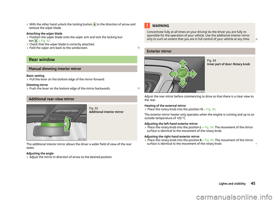
Fig. 34
Inner part of door: Rotary knob
Adjust the rear mirror before commencing to drive so that there is a clear view to
the rear.
Heating of the external mirror
› Place the rotary knob into the position
» Fig. 34.
The exterior mirror heater only operates when the engine is running and up to an
outside temperature of +20 °C.
Adjusting the left-hand exterior mirror
› Place the rotary knob into the position
» Fig. 34. The movement of the mirror
surface is identical to the movement of the rotary knob.
Adjusting the right-hand exterior mirror
› Place the rotary knob into the position
» Fig. 34. The movement of the mirror
surface is identical to the movement of the rotary knob. £
45
Lights and visibility
Page 51 of 194
›
Press the locking button in direction of the arrow
» Fig. 37 - and pull the
head restraint out.
› To re-insert the head restraint, push it far enough down into the seat backrest
until the locking button clicks into place.
Best protection is achieved if the top edge of the head restraint is at the same
level as the upper part of your head.
The head restraints must be adjusted to match the size of the seat occupant. Cor-
rectly adjusted head restraints together with the seat belts offer effective protec-
tion for the occupants » page 101.WARNING
■ The head restraints must be correctly adjusted in order to offer effective
protection for the occupants in the event of an accident.
■ Never drive with the head restraints removed - risk of injury!
■ If the rear seats are occupied, the rear head restraint must not be in the
lower position. ÐRear seats
Adjusting seats in forward/back direction
Fig. 38
Releasing at the front/rear
› Pull the lever A
» Fig. 38 up in the direction of arrow 1
or on the release loop
in direction of arrow 2
and move the seat into the desired position 3
. WARNING
The following guidelines must be observed » page 102, Correct seated posi-
tion for the occupants on the rear seats . Ð Adjusting the angle of the seat backrest
Fig. 39
Adjusting the seat backrest
› Pull the lever 1
» Fig. 39 and adjust the required inclination of the seat back-
rest. WARNING
Check for yourself that the seat backrest is engaged by pulling on it. Ð Folding the seat backrest forwards and folding the seat fully
forwards
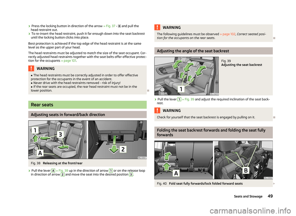
Fig. 40
Fold seat fully forwards/lock folded forward seats £
49
Seats and Stowage
Page 52 of 194
Folding the seat backrest forwards
›
Put the belt tongue into the opening on the respective side of the vehicle -
safety position.
› Remove the head restraint from the rear middle seat
» page 48, Head re-
straints.
› Push the outer rear seats towards the rear as far as they will go
» page 49,
Adjusting seats in forward/back direction .
› Pull the lever 1
» Fig. 39 on page 49 and fold the seat backrest completely for-
wards.
› Pull the lever
» Fig. 40 up before folding the seat forwards fully.
Folding seats fully forwards and locking them
› If the outer rear seat is fully folded forward, push it towards the rear as far as it
can go.
› Pull the lever A
» Fig. 40 up and fold the seat forwards fully.
› Secure the folded forward seat with the aid of the fixing belt B
to a guide rod
of the head restraint for the front seat » Fig. 40. WARNING
■ Immediately lock the folded forward seat with the aid of the fixing belt to a
guide rod of the head restraint for the front seat - risk of injury.
■ The following guidelines must be observed » page 102, Correct seated posi-
tion for the occupants on the rear seats .CAUTION
If the outer seat is not in the rear end position when folding forward, damage can
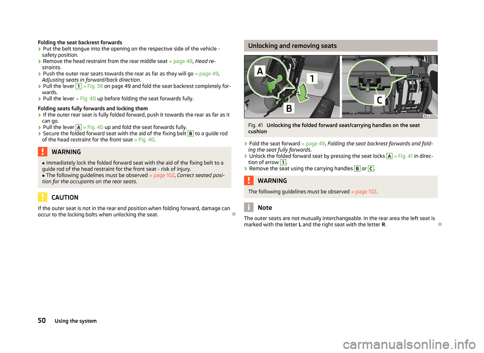
occur to the locking bolts when unlocking the seat. Ð Unlocking and removing seats
Fig. 41
Unlocking the folded forward seat/carrying handles on the seat
cushion
› Fold the seat forward
» page 49, Folding the seat backrest forwards and fold-
ing the seat fully forwards .
› Unlock the folded forward seat by pressing the seat locks A
»
Fig. 41
in direc-
tion of arrow 1
.
› Remove the seat using the carrying handles B
or C
.
WARNING
The following guidelines must be observed » page 102. Note
The outer seats are not mutually interchangeable. In the rear area the left seat is
marked with the letter L and the right seat with the letter R.Ð
50 Using the system
Page 54 of 194

Example: In the event of a frontal collision at a speed of 50 km/h, an unsecured
object with a weight of 4.5 kg produces an energy, which corresponds to 20 times
its own weight. This means that it results in a weight of approx. 90 kg
“ ”. You can
imagine the injuries that can occur, if this “object” flies through the interior com-
partment and hits an occupant. WARNING
■ Store the objects in the boot and attach them to the lashing eyes.
■ Loose objects in the passenger compartment can be thrown forward during
a sudden manoeuvre or in case of an accident and can injure the occupants or
other oncoming traffic. This risk is still increased, if the objects which are fly-
ing around are hit by a deployed airbag. In this case, the objects which are
thrown back can injure the occupants - hazard. ■ Please note that the handling properties of the vehicle may be affected
when transporting heavy objects as the centre of gravity can be displaced -
risk of accident! The speed and style of driving must be adjusted accordingly.
■ If the items of luggage or objects are attached to the lashing eyes with un-
suitable or damaged lashing straps, injuries can occur in the event of braking
manoeuvres or accidents. To prevent items of luggage from being thrown for-
ward, always use suitable lashing straps which must be firmly attached to the
lashing eyes. ■ The items carried in the boot must be stored in such a way that no objects
are able to slip forward if any sudden driving or braking manoeuvres are un-
dertaken - risk of injury!
■ When transporting fastened objects which are sharp and dangerous in the
boot that has been enlarged by folding the rear seats forward, ensure the
safety of the passengers transported on the other rear seats » page 102, Cor-
rect seated position for the occupants on the rear seats .
■ If the rear seat next to the folded forward seat is occupied, ensure maxi-
mum safety, e.g. by placing the goods to be transported in such a way that the
seat is prevented from folding back in case of a rear collision.
■ Never drive with the boot lid fully opened or slightly ajar otherwise exhaust
gases may get into the interior of the vehicle - risk of poisoning!
■ Under no circumstances, should the permissible axle loads and permissible
gross weight of the vehicle be exceeded - risk of accident!
■ Never transport people in the boot! CAUTION
Please ensure that the heating elements for the rear window heater are not dam-
aged as a result of abrasive objects. Note
Tyre pressure must be adjusted to the load »
page 149, Service life of tyres. Ð Class N1 vehicles
First read and observe the introductory information and safety warn-
ings on page 51.
On class N1 vehicles, which are not fitted with a protective grille, a lashing set
which complies with the standard EN
12195 (1 - 4) must be used for fastening the
load. Ð Fastening elements
Fig. 44
Boot: Lashing eyes and fasten-
ing elements
First read and observe the introductory information and safety warn-
ings on page 51.
The boot provides the following fastening elements
»
Fig. 44.
Lashing eyes for fastening items of luggage and fixing nets.
Fastening elements for fastening fixing nets. CAUTION
The maximum permissible load of the lashing eyes is 3.5 kN (350 kg). Ð
ä
ä
A
B
52
Using the system