ECO mode SKODA ROOMSTER 2013 1.G User Guide
[x] Cancel search | Manufacturer: SKODA, Model Year: 2013, Model line: ROOMSTER, Model: SKODA ROOMSTER 2013 1.GPages: 219, PDF Size: 13.83 MB
Page 72 of 219
stowage compartments in the luggage73Flexible storage compartment73WARNING■Do not place anything on the dash panel. These objects might slide or fall
down while you are driving (under acceleration or when cornering) and could
distract you from the traffic - there is a risk of an accident.■
Make sure that no objects from the centre console or from other storage
compartments can get into the driver's footwell while you are driving. You
would then no longer be able to apply the brakes or operate the clutch or ac-
celerator pedal – there is a risk of an accident.
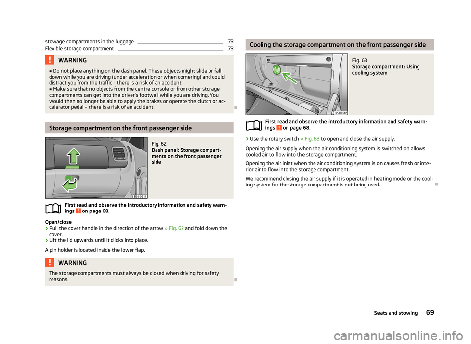
Storage compartment on the front passenger side
Fig. 62
Dash panel: Storage compart-
ments on the front passenger
side
First read and observe the introductory information and safety warn- ings on page 68.
Open/close
›
Pull the cover handle in the direction of the arrow » Fig. 62
and fold down the
cover.
›
Lift the lid upwards until it clicks into place.
A pin holder is located inside the lower flap.
WARNINGThe storage compartments must always be closed when driving for safety
reasons.
Cooling the storage compartment on the front passenger sideFig. 63
Storage compartment: Using
cooling system
First read and observe the introductory information and safety warn-
ings on page 68.
›
Use the rotary switch » Fig. 63 to open and close the air supply.
Opening the air supply when the air conditioning system is switched on allows
cooled air to flow into the storage compartment.
Opening the air inlet when the air conditioning system is on causes fresh or inte-rior air to flow into the storage compartment.
We recommend closing the air supply if it is operated in heating mode or the cool-ing system for the storage compartment is not being used.
69Seats and stowing
Page 80 of 219
Heating and air-conditioning
Heating, ventilation, cooling
Introduction
This chapter contains information on the following subjects:
Air outlets
77
Using the air conditioning system economically
78
Operational problems
78
The heating effect is dependent upon the coolant temperature, thus full heat
output only occurs when the engine has reached its operating temperature.
If the cooling system is switched on, the temperature and air humidity drops in
the vehicle. The cooling system prevents the windows from misting up when out- side temperatures are particularly low.
It is possible to briefly activate recirculated air mode to enhance the cooling ef- fect.
Please refer to the information regarding recirculated air mode for the air-condi- tioning system » page 82 or for Climatronic » page 84.
WARNINGFor your own safety and that of other road users, ensure that all the windows
are free of ice, snow and misting. Please familiarize yourself about how to cor- rectly operate the heating and ventilation systems, how to demist and defrost
the windows, as well as with the cooling mode.
CAUTION
■ The air inlet in front of the windscreen must be free (e.g. of ice, snow or leaves)
to ensure that the heating and cooling system operates properly.■
After switching on the cooling Condensation from the evaporator of the air con-
ditioning may drip down and form a puddle below the vehicle. This is not a leak.
Note■ The exhaust air streams out through vents at the rear of the luggage compart-
ment.■
We recommend that you do not smoke in the vehicle when the recirculating air
mode is operating since the smoke which is drawn at the evaporator from the in- terior of the vehicle forms deposits in the evaporator of the air conditioning sys-tem. This produces a permanent odour when the air conditioning system is oper-ating which can only be eliminated through considerable effort and expense (re-
placement of compressor).
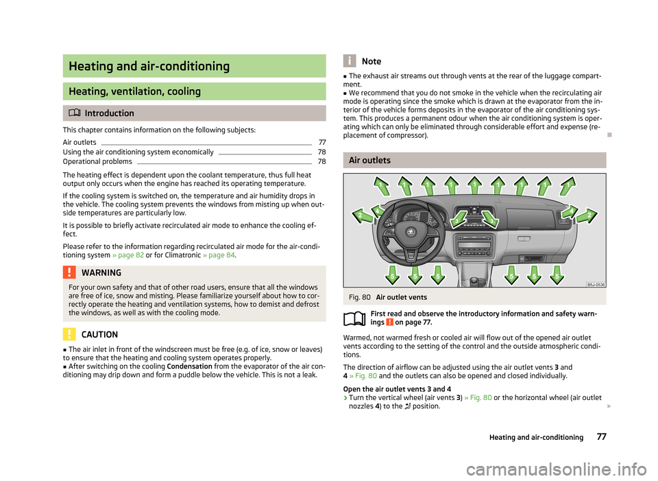
Air outlets
Fig. 80
Air outlet vents
First read and observe the introductory information and safety warn-
ings
on page 77.
Warmed, not warmed fresh or cooled air will flow out of the opened air outlet
vents according to the setting of the control and the outside atmospheric condi-
tions.
The direction of airflow can be adjusted using the air outlet vents 3 and
4 » Fig. 80 and the outlets can also be opened and closed individually.
Open the air outlet vents 3 and 4
›
Turn the vertical wheel (air vents 3) » Fig. 80 or the horizontal wheel (air outlet
nozzles 4) to the
position.
77Heating and air-conditioning
Page 81 of 219
Close air outlet vents 3 and 4›Turn the vertical wheel (air vents 3) » Fig. 80 or the horizontal wheel (air outlet
nozzles 4) to the 0 position.
Change air flow of air outlet vents 3 and 4›
In order to change the strength of the air flow, swivel the horizontal lamellas with the aid of the moveable adjuster » Fig. 80.
›
In order to change the lateral direction of the air flow, swivel the vertical lamel-
las with the aid of the moveable adjuster.
Set the air supply to the individual vents with the air distribution control
C
» Fig. 81 on page 79.
Note
Do not cover the air outlet vents with objects of any kind.
Using the air conditioning system economically
First read and observe the introductory information and safety warn-ings
on page 77.
The air conditioning system compressor uses power from the engine when in
cooling mode, which will affect the fuel consumption.
It recommended to open the windows or the doors of a vehicle for which the inte-rior has been strongly heated through the effect of direct sunlight in order to al-
low the heated air to escape.
The cooling system should not be switched on if the windows are open.
For the sake of the environment
Pollutant emissions are also lower when fuel is being saved » page 104.
Operational problems
First read and observe the introductory information and safety warn-
ings
on page 77.
If the cooling system does not operate at outside temperatures higher than +5 °C,
there is a problem in the system. The reasons for this may be.
› One of the fuses has blown. Check the fuse and replace if necessa-
ry » page 191 .
› The cooling system has switched off automatically for a short time because the
coolant temperature of the engine is too hot » page 11.
If you are not able to resolve the operational problem yourself, or if the cooler
output has reduced, switch off the cooling system and seek assistance from a
specialist garage.
Heating
Introduction
This chapter contains information on the following subjects:
Operation
79
Setting
79
Recirculated air mode
80
78Operation
Page 82 of 219
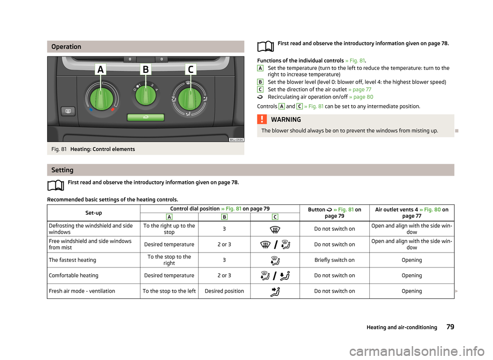
OperationFig. 81
Heating: Control elements
First read and observe the introductory information given on page 78.
Functions of the individual controls » Fig. 81 .
Set the temperature (turn to the left to reduce the temperature: turn to the right to increase temperature)
Set the blower level (level 0: blower off, level 4: the highest blower speed) Set the direction of the air outlet » page 77
Recirculating air operation on/off » page 80
Controls
A
and
C
» Fig. 81 can be set to any intermediate position.
WARNINGThe blower should always be on to prevent the windows from misting up.
ABC
Setting
First read and observe the introductory information given on page 78.
Recommended basic settings of the heating controls.
Set-upControl dial position » Fig. 81 on page 79Button » Fig. 81 on
page 79Air outlet vents 4 » Fig. 80 on
page 77ABCDefrosting the windshield and side
windowsTo the right up to the stop3Do not switch onOpen and align with the side win- dowFree windshield and side windows
from mistDesired temperature2 or 3
Do not switch onOpen and align with the side win-
dowThe fastest heatingTo the stop to theright3Briefly switch onOpeningComfortable heatingDesired temperature2 or 3
Do not switch onOpeningFresh air mode - ventilationTo the stop to the leftDesired positionDo not switch onOpening 79Heating and air-conditioning
Page 83 of 219
We recommend that you leave the air outlet vents 3 » Fig. 80 on page 77 in the
open position in all operating modes.
Note
If the air distribution is set only to the windows, the entire volume of air is used
to defrost the windows and thus no air will be fed to the footwell. This can limit
the heating comfort.
Recirculated air mode
First read and observe the introductory information given on page 78.
Recirculated air mode prevents polluted air from outside the vehicle getting into
the vehicle, for example when driving through a tunnel or when standing in a
traffic jam.
Switching on/off
›
Press the
button.
The indicator light in the button lights up.
›
Press the
button again.
The indicator light in the button goes out.
Recirculated air mode is switched off automatically if the air distribution control
C
» Fig. 81 on page 79 is turned to the
position. Recirculated air mode can be
switched on again from this setting by pressing the
button again.
WARNINGNever leave recirculated air mode on over a longer period of time, as “stale air”
can cause fatigue of the driver and the passengers, reduce attention levels
and also cause the windows to mist up. The risk of having an accident increa-
ses. Switch off recirculated air mode as soon as the windows start to mist up.
Air conditioning system (manual air conditioning
system)
Introduction
This chapter contains information on the following subjects: Operation
81
Setting the air conditioning system
82
Recirculated air mode
82
The cooling system operates only if the following conditions are met. The cooling system is switched on » page 81.
The engine is running.
The outside temperature is above approximately +2 °C.
The blower switch is switched on (positions 1-4).
If the desired interior temperature can also be achieved without activating the cooling system, fresh air mode should be selected.
If the coolant temperature is too high, the cooling system is switched off to en-
sure that the engine cools down.
CAUTION
■ Under certain circumstances, air at a temperature of about 5 °C can flow out of
the vents when the cooling system is switched on.■
Lengthy and uneven distribution of the air flow out of the vents (especially
around the feet) and large differences in temperature, for example, when getting
out of the vehicle, can cause susceptible individuals to catch a cold.
Note
We recommend that you have the air conditioning system cleaned by a specialist
garage once every year.80Operation
Page 85 of 219
Setting the air conditioning systemFirst read and observe the introductory information and safety warnings
on page 80.
Recommended basic settings of the air conditioning controls.
Set-upControl dial position » Fig. 82 on page 81Button » Fig. 82 on page 81Air outlet vents 4 » Fig. 80
on page 77ABC
Defrost/defog windscreen and
side windows a)Desired tempera-
ture3 or 4Do not switch onAutomatically switched onOpen and align with the sidewindowThe fastest heatingTo the stop to theright3Briefly switch onSwitched offOpeningComfortable heatingDesired tempera-
ture2 or 3
Do not switch onSwitched offOpeningThe fastest coolingTo the left up to
the stopbriefly 4, then 2 or 3Briefly switch on b)ActivatedOpeningOptimal coolingDesired tempera-
ture1, 2 or 3Do not switch onActivatedOpen and align to the roofFresh air mode - ventilationTo the stop to the leftDesired positionDo not switch onSwitched offOpeninga)
We recommend that you do not use this setting in countries with high humidity levels. This can result in heavy cooling of the window glass and the following fogging from outside.
b)
Under certain conditions, recirculated air mode » page 82 may come on automatically; the warning light will then light up in the
button.
We recommend that you leave the air outlet vents
3 » Fig. 80 on page 77 in the
open position in all operating modes.
Recirculated air mode
First read and observe the introductory information and safety warn-ings
on page 80.
Recirculated air mode prevents polluted air from outside the vehicle getting into
the vehicle, for example when driving through a tunnel or when standing in a traffic jam.
Switching on/off
›
Press the
button.
The indicator light in the button lights up.›
Press the button again.
The indicator light in the button goes out.
Recirculated air mode is switched off automatically if the air distribution control
C
» Fig. 82 on page 81 is turned to the position.
Recirculated air mode can be switched on again from this setting by pressing the
button again.
82Operation
Page 86 of 219

WARNINGNever leave recirculated air mode on over a longer period of time, as “stale air”
can cause fatigue of the driver and the passengers, reduce attention levels and also cause the windows to mist up. The risk of having an accident increa-
ses. Switch off recirculated air mode as soon as the windows start to mist up.
Climatronic (automatic air conditioning system)
Introduction
This chapter contains information on the following subjects:
Control elements
83
automatic mode
84
Setting the temperature
84
Recirculated air mode
84
Controlling blower
85
Defrosting windscreen
85
The Climatronic in automatic mode ensures the best-possible setting of the tem-
perature of the outflowing air, the blower stage and air distribution.
The system also takes sunlight into account, which eliminates the need to alterthe settings manually.
The cooling system operates only if the following conditions are met. The cooling system is switched on » page 83.
The engine is running.
The outside temperature is above approximately +2 °C.
If the coolant temperature is too high, the cooling system is switched off to en- sure that the engine cools down.
Note
We recommend that you have Climatronic cleaned by a specialist garage once ev-
ery year.Control elementsFig. 83
Climatronic: Control elements
First read and observe the introductory information given on page 83.
The buttons/control dial Setting the interior temperature » page 84
Display
Display of selected interior temperature
Degrees Celsius or Fahrenheit, change the displayed temperature units » page 84
Automatic operation of the air conditioning system Ventilation or defrosting of the windscreen activated
Direction of air flow
Recirculated air mode activated
Cooling system activated
Blower speed set
The buttons/control dial Adjust the blower speed » page 85
Interior temperature sensor Automatic mode » page 84
De-mist or de-ice the windscreen » page 85
123456789101183Heating and air-conditioning
Page 89 of 219
Communication and multimedia
Universal telephone preinstallation GSM II
Introduction
This chapter contains information on the following subjects:
Mobile phones and two-way radio systems
86
Introductory information
86
Phone Phonebook
87
Operating the phone on the multifunction steering wheel
87
Inserting the mobile phone and adapter
88
Managing telephone calls with the help of the adapter
89
Connecting the mobile phone to the hands-free system
89
Symbols in the MAXI DOT display
90
Telephone operation in the MAXI DOT display
90
Mobile phones and two-way radio systems
First read and observe the introductory information given on page 86.
ŠKODA permits the operation of mobile phones and two-way radio systems with
a professionally installed external aerial and a maximum transmission power of
up to 10 watts.
Please consult a ŠKODA Partner for information about the possibility of installing
and operating mobile phones and two-way radio systems with a transmission
power of more than 10 W.
Operating mobile phones or two-way radio systems may interfere with the func-tionality of the electronic systems in your vehicle.
This could be for the following reasons.
› no external aerial.
› external aerial incorrectly installed.
› transmission power greater than 10 watts.
WARNING■
Concentrate fully at all times on your driving! As the driver you are fully re-
sponsible for road safety. Use the telephone system only to such an extent that you are in full control of your vehicle at any time.■
The national regulations for using a mobile phone in a vehicle must be ob-
served.
■
If a mobile phone or a two-way radio system is operated in a vehicle without
an external aerial or an external aerial which has been installed incorrectly,
this can increase the strength of the electromagnetic field inside the vehicle.
■
Two-way radio systems, mobile phones or mounts must not be installed on
airbag covers or within the immediate deployment range of the airbags.
■
Never leave a mobile phone on a seat, on the dash panel or in another area,
from which it can be thrown during a sudden braking manoeuvre, an accident
or a collision - risk of injury.
■
The Bluetooth ®
function must be switched off by a specialist workshop be-
fore the vehicle is transported by air.
Note
■ We recommend that mobile phones and two-way radio systems be installed in
the a vehicle by a specialist workshop.■
Not all mobile phones that enable Bluetooth ®
communication are compatible
with the universal telephone preinstallation GSM II. You can ask a ŠKODA Partner
whether your telephone is compatible with the GSM II universal telephone fitting.
■
The range of the Bluetooth ®
connection to the hands-free system is restricted
to the vehicle interior. The range is dependent on local factors, e.g. obstacles be-
tween the devices and mutual interferences with other devices. If your mobile
phone is in a jacket pocket, for example, this can lead to difficulties when estab-
lishing a connection with the hands-free-system or transferring data.
Introductory information
First read and observe the introductory information given on page 86.
The universal telephone preinstallation GSM II (hands-free system) includes a
convenience mode for the mobile phone via voice control, the multifunction
steering wheel, the adapter, radio or the navigation system.
86Operation
Page 104 of 219
Modes and use of selector leverFig. 92
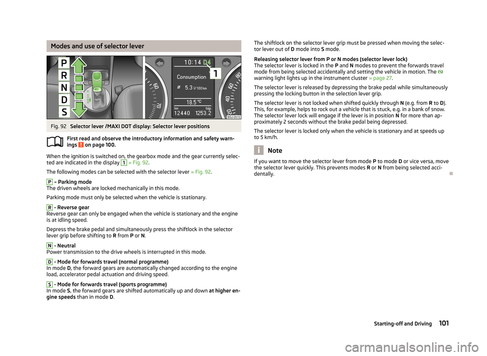
Selector lever /MAXI DOT display: Selector lever positions
First read and observe the introductory information and safety warn- ings
on page 100.
When the ignition is switched on, the gearbox mode and the gear currently selec-
ted are indicated in the display
1
» Fig. 92 .
The following modes can be selected with the selector lever » Fig. 92.
P
– Parking mode
The driven wheels are locked mechanically in this mode.
Parking mode must only be selected when the vehicle is stationary.
R
- Reverse gear
Reverse gear can only be engaged when the vehicle is stationary and the engine
is at idling speed.
Depress the brake pedal and simultaneously press the shiftlock in the selector
lever grip before shifting to R from P or N.
N
- Neutral
Power transmission to the drive wheels is interrupted in this mode.
D
- Mode for forwards travel (normal programme)
In mode D, the forward gears are automatically changed according to the engine
load, accelerator pedal actuation and driving speed.
S
- Mode for forwards travel (sports programme)
In mode S, the forward gears are shifted automatically up and down at higher en-
gine speeds than in mode D.
The shiftlock on the selector lever grip must be pressed when moving the selec-
tor lever out of D mode into S mode.
Releasing selector lever from P or N modes (selector lever lock) The selector lever is locked in the P and N modes to prevent the forwards travel
mode from being selected accidentally and setting the vehicle in motion. The
warning light lights up in the instrument cluster » page 27.
The selector lever is released by depressing the brake pedal while simultaneously
pressing the locking button in the selection lever grip.
The selector lever is not locked when shifted quickly through N (e.g. from R to D).
This, for example, helps to rock out a vehicle that is stuck, e.g. in a bank of snow.
The selector lever lock will engage if the lever is in position N for more than ap-
proximately 2 seconds without the brake pedal being depressed.
The selector lever is locked only when the vehicle is stationary and at speeds up
to 5 km/h.
Note
If you want to move the selector lever from mode P to mode D or vice versa, move
the selector lever quickly. This prevents modes R or N from being selected acci-
dentally.
101Starting-off and Driving
Page 106 of 219
MalfunctionFirst read and observe the introductory information and safety warn-
ings
on page 100.
Emergency programme
The transmission switches to the emergency programme if there is a fault in the
automatic gearbox system.
Indications of an activated emergency programme include the following:
› Only certain gears are selected.
› Reverse gear
R cannot be used.
› Shifting gears in Tiptronic mode is not possible.
Gearbox overheating
The gearbox may, for example, become too hot due to frequent repeated starting
or stop-and-go traffic. Overheating is indicated by the warning light » page 19,
Clutches in the automatic gearbox are too hot .
Note
Visit a specialist workshop if the gearbox has switched to the emergency pro-
gramme.
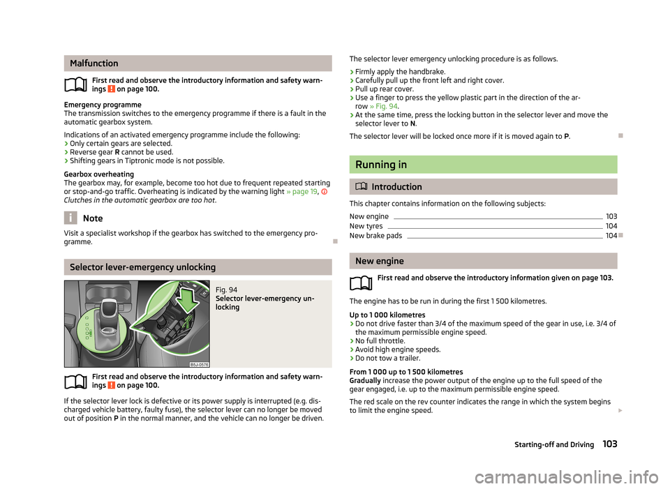
Selector lever-emergency unlocking
Fig. 94
Selector lever-emergency un-
locking
First read and observe the introductory information and safety warn-
ings on page 100.
If the selector lever lock is defective or its power supply is interrupted (e.g. dis-
charged vehicle battery, faulty fuse), the selector lever can no longer be moved
out of position P in the normal manner, and the vehicle can no longer be driven.
The selector lever emergency unlocking procedure is as follows.›
Firmly apply the handbrake.
›
Carefully pull up the front left and right cover.
›
Pull up rear cover.
›
Use a finger to press the yellow plastic part in the direction of the ar-
row » Fig. 94 .
›
At the same time, press the locking button in the selector lever and move the
selector lever to N.
The selector lever will be locked once more if it is moved again to P.
Running in
Introduction
This chapter contains information on the following subjects:
New engine
103
New tyres
104
New brake pads
104
New engine
First read and observe the introductory information given on page 103.
The engine has to be run in during the first 1 500 kilometres.Up to 1 000 kilometres
›
Do not drive faster than 3/4 of the maximum speed of the gear in use, i.e. 3/4 of
the maximum permissible engine speed.
›
No full throttle.
›
Avoid high engine speeds.
›
Do not tow a trailer.
From 1 000 up to 1 500 kilometres
Gradually increase the power output of the engine up to the full speed of the
gear engaged, i.e. up to the maximum permissible engine speed.
The red scale on the rev counter indicates the range in which the system beginsto limit the engine speed.
103Starting-off and Driving