tyre pressure SKODA ROOMSTER 2013 1.G User Guide
[x] Cancel search | Manufacturer: SKODA, Model Year: 2013, Model line: ROOMSTER, Model: SKODA ROOMSTER 2013 1.GPages: 219, PDF Size: 13.83 MB
Page 177 of 219
Always check the inflation pressure when the tyres are cold. Do not reduce the
higher pressure of warm tyres.
With greater additional load, adjust the tyre inflation pressure accordingly.
Driving style
Fast cornering, sharp acceleration and braking increase the wear of your tyres.
Balancing wheels
The wheels of a new vehicle are balanced. When driving, however, there are a
range of factors that may result in an imbalance. This may become apparent by
“vibration” in the steering.
Have the wheels rebalanced after replacing the tyres.
Wheel alignment errors
Incorrect wheel alignment at the front or rear leads to excess wear of the tyres.
Tyre damage
Drive over kerbs and other such obstacles slowly and at right angles wherever
possible in order to avoid damage to tyres and wheel trims.
We recommend checking your tyres and wheel rims for damage (punctures, cuts,
splits and bulges, etc.) on a regular basis. Remove foreign bodies (e.g. small
stones) from the tyre tread immediately.
Replacing wheels
If significantly greater wear is present on the front tyres, we recommend swap-
ping the front wheels with the rear wheels as shown in the diagram » Fig. 136.
You will then obtain approximately the same life for all the tyres.
We recommend that you swap the tyres every 10,000 km in order to achieve evenwear on all tyres and to ensure optimal service life for the tyres.
Storing tyres
Identify disassembled tyres so that the previous direction of rotation can be
maintained if the tyres are reassembled.
Always store wheels or tyres in a cool, dry place that is as dark as possible. Tyres
which are not fixed to a wheel trim should be stored upright.
Wear indicators
The base of the tread of the tyres has 1.6 mm high wear indicators installed.
These wear indicators are arranged evenly spaced around the circumference of the tyre a number of times depending on the make » Fig. 135 -
. Markings on the
walls of the tyres through the letters “TWI”, triangular symbols or other symbols identify the position of the wear indicators.Tyre age
Tyres age and lose their original characteristics, even if they are not being used.
Therefore, we recommend not using summer or winter tyres older than 6 or 4 years old respectively.
New tyres
First read and observe the introductory information and safety warn-
ings
on page 172.
Only use radial tyres of the same type, size (rolling circumference) and tread pat-
tern on one axle on all four wheels.
The tyre/wheel combinations which are approved for your vehicle are indicated in
your vehicle documents.
Where possible, replace tyres by axle. Always fit the tyres with the deeper tread
depth to the front wheels.
Explanation of tyre markings
185/65 R 14 86 T
What this means is:
185Tyre width in mm » Fig. 135 on page 173 - 65Height/width ratio in % » Fig. 135 on page 173 - RCode letter for the tyre construction – Radial » Fig. 135 on page 173
- 14Diameter of wheel in inches » Fig. 135 on page 173 - 86Load index » TSpeed symbol »
The date of manufacture is stated on the tyre wall (possibly on the inside). e.g.
DOT ... 10 13...
means, for example, that the tyre was manufactured in the 10th week of 2013.
Load index
This indicates the maximum permissible load for each individual tyre. 487 kg
515 kg
530 kg
838586174General Maintenance
Page 178 of 219
545 kg
615 kg
630 kg
650 kg
Speed symbol
This indicates the maximum permissible vehicle speed with fitted tyres in each
category.
170 km/h
180 km/h
190 km/h
200 km/h
210 km/h
240 km/h
270 km/h
CAUTION
The information about the load index and the speed symbol is listed in your vehi-
cle documents.
Unidirectional tyres
First read and observe the introductory information and safety warn-
ings
on page 172.
The direction of rotation of the tyres is marked by arrows on the wall of the tyre.
The indicated direction of rotation must be adhered to in order to ensure the op- timal characteristics of these tyres.
These characteristics mainly relate to the following: › Increased driving stability.
› Reduced risk of aquaplaning.
› Reduced tyre noise and tyre wear.
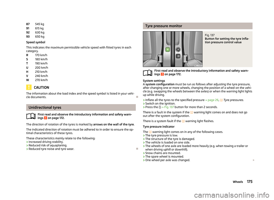
87919293RSTUHVWTyre pressure monitorFig. 137
Button for setting the tyre infla-
tion pressure control value
First read and observe the introductory information and safety warn-
ings on page 172.
System settings
A system configuration must be run as follows after adjusting the tyre pressure,
after changing one or more wheels, changing the position of a wheel on the vehi- cle (e.g. swapping the wheels between the axles) or when the warning light lights
up while driving.
›
Inflate all the tyres to the specified pressure » page 26,
Tyre pressures .
›
Switch on the ignition.
›
Press the
» Fig. 137 button for more than 2 seconds.
There is a fault in the system if the
warning light comes on and does not go
out after the system configuration.
There is a system fault if the
warning light flashes.
Tyre pressure indicator
The
warning light comes on in any of the following cases.
› The tyre pressure is low.
› The structure of the tyre is damaged.
› The vehicle is loaded on one side.
› The wheels of one axle are loaded more heavily (e.g. when towing a trailer or
when driving uphill or downhill).
› Snow chains are mounted.
› The spare wheel is mounted.
› One wheel per axle was changed.
175Wheels
Page 179 of 219
WARNING■When the warning light illuminates, immediately reduce the speed and
avoid sudden steering and brake manoeuvres. Stop the vehicle as soon as
possible and inspect the tyres and their inflation pressure.■
Under certain circumstances (e.g. a racy style of driving, wintry or unpaved
roads), the warning light may be delayed or does not light up at all.
CAUTION
■
The tyre control display does therefore not replace the regular tyre inflation
pressure control, as the system cannot detect an even loss of pressure.■
The system cannot warn in case of very rapid loss of tyre pressure, e.g. in the
event of a sudden puncture. In this case carefully bring the vehicle to a standstill without sudden steering movements or sharp braking.
■
The basic setting must be repeated every 10,000 km or once a year to ensure
proper functioning of the tyre pressure monitor.
Spare wheel
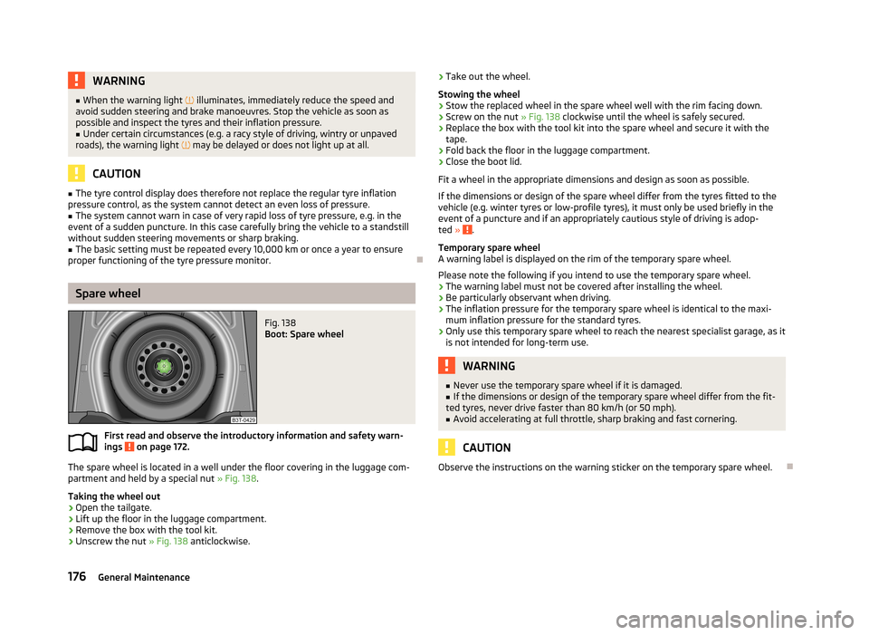
Fig. 138
Boot: Spare wheel
First read and observe the introductory information and safety warn-
ings on page 172.
The spare wheel is located in a well under the floor covering in the luggage com-
partment and held by a special nut » Fig. 138.
Taking the wheel out
›
Open the tailgate.
›
Lift up the floor in the luggage compartment.
›
Remove the box with the tool kit.
›
Unscrew the nut » Fig. 138 anticlockwise.
›Take out the wheel.
Stowing the wheel›
Stow the replaced wheel in the spare wheel well with the rim facing down.
›
Screw on the nut » Fig. 138 clockwise until the wheel is safely secured.
›
Replace the box with the tool kit into the spare wheel and secure it with the
tape.
›
Fold back the floor in the luggage compartment.
›
Close the boot lid.
Fit a wheel in the appropriate dimensions and design as soon as possible.
If the dimensions or design of the spare wheel differ from the tyres fitted to the
vehicle (e.g. winter tyres or low-profile tyres), it must only be used briefly in the
event of a puncture and if an appropriately cautious style of driving is adop-
ted »
.
Temporary spare wheel
A warning label is displayed on the rim of the temporary spare wheel.
Please note the following if you intend to use the temporary spare wheel. › The warning label must not be covered after installing the wheel.
› Be particularly observant when driving.
› The inflation pressure for the temporary spare wheel is identical to the maxi-
mum inflation pressure for the standard tyres.
› Only use this temporary spare wheel to reach the nearest specialist garage, as it
is not intended for long-term use.
WARNING■ Never use the temporary spare wheel if it is damaged.■If the dimensions or design of the temporary spare wheel differ from the fit-
ted tyres, never drive faster than 80 km/h (or 50 mph).■
Avoid accelerating at full throttle, sharp braking and fast cornering.
CAUTION
Observe the instructions on the warning sticker on the temporary spare wheel.
176General Maintenance
Page 180 of 219
Full wheel trimFirst read and observe the introductory information and safety warn-
ings
on page 172.
Pulling off
›
Hook the clamp found in the vehicle tool kit into the reinforced edge of the wheel trim.
›
Push the wheel wrench through the clamp, support on the tyre and pull off the
wheel trim.
Fitting
›
Press the wheel trim onto the wheel rim at the designated valve opening.
›
Then press the trim into the wheel rim until its entire circumference locks cor- rectly in place.
CAUTION
■ Only apply hand pressure, do not hit the full wheel trim! Avoid heavy impacts
when the trim has not yet been inserted into the wheel rim. This could cause
damage to the guide and centring elements of the trim.■
Make sure that the anti-theft wheel bolt is fitted in the bore near the
valve » page 183 , Securing wheels against theft .
■
If wheel trims are retrofitted it must be ensured that an adequate flow of air is
assured to cool the brake system.
Wheel bolts
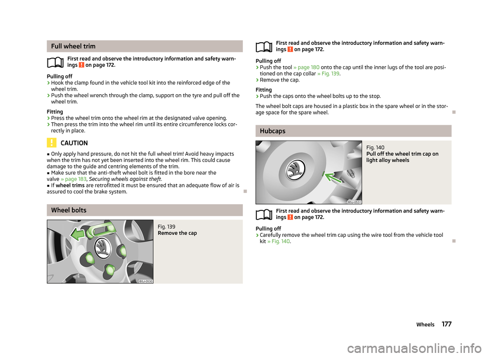
Fig. 139
Remove the capFirst read and observe the introductory information and safety warn-
ings on page 172.
Pulling off
›
Push the tool » page 180 onto the cap until the inner lugs of the tool are posi-
tioned on the cap collar » Fig. 139.
›
Remove the cap.
Fitting
›
Push the caps onto the wheel bolts up to the stop.
The wheel bolt caps are housed in a plastic box in the spare wheel or in the stor-
age space for the spare wheel.
Hubcaps
Fig. 140
Pull off the wheel trim cap on
light alloy wheels
First read and observe the introductory information and safety warn-
ings on page 172.
Pulling off
›
Carefully remove the wheel trim cap using the wire tool from the vehicle tool
kit » Fig. 140 .
177Wheels
Page 185 of 219
Follow-up workFirst read and observe the introductory information and safety warn-
ings
on page 180.
The following steps must also be performed after changing the wheel.
›
Stow and attach the replaced wheel in the spare wheel well using a special screw » page 176 , Spare wheel .
›
Stow the tool kit in the space provided and secure using the strap.
›
Check the tyre pressure on the installed spare wheel as soon as possible.
›
Have the tightening torque of the wheel bolts checked with a torque wrench
as soon as possible.
›
Replace the damaged wheel or consult a specialist garage about repair options.
Note
■ If it is determined that the wheel bolts are corroded and difficult to turn when
changing the wheel, the bolts must be replaced before checking the tightening
torque.■
Drive cautiously and only at a moderate speed until the tightening torque has
been checked.
Loosening/tightening wheel bolts
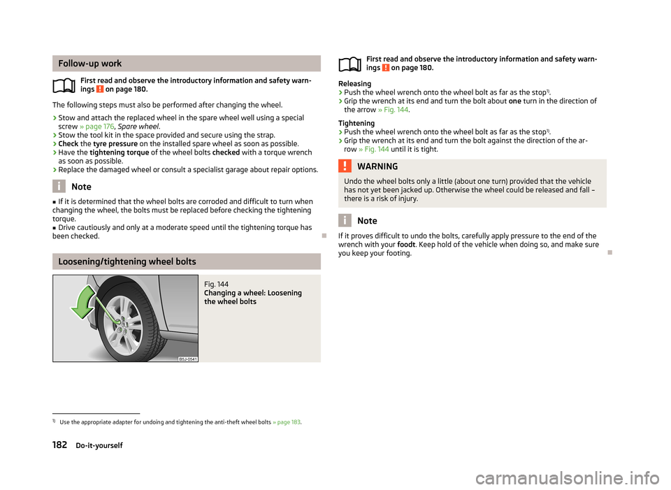
Fig. 144
Changing a wheel: Loosening
the wheel boltsFirst read and observe the introductory information and safety warn-
ings on page 180.
Releasing
›
Push the wheel wrench onto the wheel bolt as far as the stop 1)
.
›
Grip the wrench at its end and turn the bolt about one turn in the direction of
the arrow » Fig. 144.
Tightening
›
Push the wheel wrench onto the wheel bolt as far as the stop 1)
.
›
Grip the wrench at its end and turn the bolt against the direction of the ar-
row » Fig. 144 until it is tight.
WARNINGUndo the wheel bolts only a little (about one turn) provided that the vehicle
has not yet been jacked up. Otherwise the wheel could be released and fall –
there is a risk of injury.
Note
If it proves difficult to undo the bolts, carefully apply pressure to the end of the
wrench with your foodt. Keep hold of the vehicle when doing so, and make sure
you keep your footing.
1)
Use the appropriate adapter for undoing and tightening the anti-theft wheel bolts » page 183.
182Do-it-yourself
Page 187 of 219
Note■Make a note of the code number hammered into the rear side of the adapter or
the rear side of the anti-theft wheel bolt. This number can be used to purchase a
replacement adapter from ŠKODA Original Parts if necessary.■
We recommend that you always carry the adapter for the wheel bolts with you
in the vehicle. It should be stowed in the vehicle tool kit.
■
The anti-theft wheel bolt set and adapter can be purchased from a ŠKODA Part-
ner.
Tyre repair
Introduction
This chapter contains information on the following subjects:
Breakdown kit
185
Preparations for using the breakdown kit
185
Sealing and inflating the tyre
185
Check after 10 minutes' driving
186
Use the breakdown kit to reliably repair tyre damage caused by foreign bodies or
a puncture with diameters up to approx. 4 mm.
A repair made using the breakdown kit is never intended to replace a permanent
repair on the tyre. Its purpose is to get you to the nearest specialist garage.
The wheel need not be removed during the repair.
Do not remove foreign bodies , e.g. screws or nails, from the tyre.
The breakdown kit must not be used under the following circumstances. › There is damage to the rim.
› The outside temperature is less than -20 °C.
› The tears or punctures are greater than 4 mm in size.
› There is damage to the tyre wall.
› Driving with very low tyre pressure or with a completely flat tyre.
› If the use-by-date (see inflation bottle) has passed.
WARNING■
A tyre filled with sealant has the same driving characteristics as a standard
tyre.■
Do not travel faster than 80 km/h.
■
Avoid accelerating at full throttle, sharp braking and fast cornering.
■
Check the tyre pressure after driving for 10 minutes.
■
The sealant is hazardous to heath. Remove immediately if it comes into con-
tact with the skin.
For the sake of the environment
Used sealant or sealant whose expiry date has passed must be disposed of in ac- cordance with environmental protection regulations.
Note
■ Observe the manufacturer's usage instructions for the breakdown kit.■A new bottle of sealant can be purchased from ŠKODA Original Parts.■
Immediately replace the tyre that was repaired using the breakdown kit, or con-
sult a specialist garage about repair options.
184Do-it-yourself
Page 188 of 219
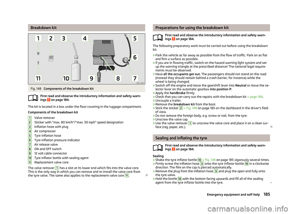
Breakdown kitFig. 148
Components of the breakdown kit
First read and observe the introductory information and safety warn-
ings
on page 184.
The kit is located in a box under the floor covering in the luggage compartment.
Components of the breakdown kit Valve remover
Sticker with “max. 80 km/h”/“max. 50 mph” speed designation
Inflation hose with plug
Air compressor
Tyre inflation hose
Tyre inflation pressure indicator
Air release valve
ON and OFF switch
12 volt cable connector
Tyre inflator bottle with sealing agent
Replacement valve core
The valve remover
1
has a slot at its lower end which fits into the valve core.
This is the only way in which you can remove and re-install the valve core from
the tyre valve. The same also applies to the replacement valve core
11
.
1234567891011Preparations for using the breakdown kit
First read and observe the introductory information and safety warn-
ings
on page 184.
The following preparatory work must be carried out before using the breakdown
kit.
›
Park the vehicle as far away as possible from the flow of traffic. Park on as flat and firm a surface as possible.
›
If you are in flowing traffic, switch on the hazard warning light system and setup the warning triangle at the prescribed distance! The national legal require-
ments must be observed.
›
Have all the occupants get out. The passengers should not stand on the road
(instead they should remain behind a crash barrier, for instance) while the wheel is being changed.
›
Switch off the engine and move the gearshift lever into Neutral or move the se-
lector lever on the automatic gearbox into position P.
›
Apply the handbrake firmly.
›
Check that you can carry out the repairs with the breakdown kit » page 184.
›
Uncouple a trailer.
›
Remove the breakdown kit from the boot.
›
Stick the sticker
2
» Fig. 148 on page 185 on the dashboard in the driver's field
of view.
›
Do not remove the foreign body, e.g. screw or nail, from the tyre.
›
Unscrew the valve cap.
›
Use the valve remover
1
to unscrew the valve core and place it on a clean sur-
face (rag, paper, etc.).
Sealing and inflating the tyre
First read and observe the introductory information and safety warn-
ings
on page 184.
Sealing
›
Shake the tyre inflator bottle
10
» Fig. 148 on page 185 vigorously several times.
›
Firmly screw the inflation hose
3
onto the tyre inflator bottle
10
in a clockwise
direction. The film on the cap is pierced automatically.
›
Remove the plug from the inflation hose
3
and plug the open end fully onto
the tyre valve.
›
Hold the bottle
10
with the bottom facing upwards and fill all of the sealing
agent from the tyre inflator bottle into the tyre.
185Emergency equipment and self-help
Page 189 of 219
›Remove the empty tyre inflator bottle from the valve.›Screw the valve core back into the tyre valve using the valve remover 1.
Inflating›
Screw the air compressor tyre inflation hose
5
» Fig. 148 on page 185 firmly on-
to the tyre valve.
›
Check that the air release valve
7
is closed.
›
Start the engine and run it in idle.
›
Plug the connector
9
into 12 Volt socket » page 67, 12-volt power outlet .
›
Switch on the air compressor with the ON and OFF switch
8
.
›
Allow the air compressor to run until a pressure of 2.0 - 2.5 bar is achieved. Max-
imum run time of 8 minutes » !
›
Switch off the air compressor.
›
If you cannot reach an air pressure of 2.0 – 2.5 bar, unscrew the tyre inflation
hose
5
from the tyre valve.
›
Drive the vehicle 10 metres forwards or backwards to allow the sealing agent to
“distribute” in the tyre.
›
Firmly screw the tyre inflation hose
5
back onto the tyre valve and repeat the
inflation process.
›
If you cannot reach the required tyre inflation pressure here either, this means
the tyre has sustained too much damage. You cannot seal with tyre with the breakdown kit »
.
›
Switch off the air compressor.
›
Remove the tyre inflation hose
5
from the tyre valve.
Once a tyre pressure of 2.0 – 2.5 bar is reached, the journey may be continued at a maximum speed of 80 km/h (50 mph).
Check the tyre inflation pressure after driving for 10 minutes » page 186.
WARNING■
The tyre inflation hose and air compressor may get hot as the tyre is being
inflated – there is a risk of injury.■
Do not place the hot tyre inflation hose or hot air compressor on flammable
materials – there is a risk of fire.
■
If you cannot inflate the tyre to at least 2.0 bar, this means the damage sus-
tained was too serious. The sealing agent cannot be used to seal the tyre.
Do not drive the vehicle. Seek help from a specialist garage.
CAUTIONSwitch off the air compressor after running 8 minutes at the latest – there is a
risk of overheating. Allow the air compressor to cool a few minutes before switch- ing it on again.
Check after 10 minutes' driving
First read and observe the introductory information and safety warn-ings
on page 184.
Check the tyre inflation pressure after driving for 10 minutes!
If the tyre pressure is 1.3 bar or less
›
Do not drive the vehicle! You cannot properly seal with tyre with the break-
down kit.
If the tyre pressure is 1.3 bar or more
›
Adjust the tyre pressure to the correct value again (see inside of fuel filler cap).
›
Continue driving carefully to the nearest specialist garage at a maximum speed
of 80 km/h (50 mph).
Jump-starting
Introduction
This chapter contains information on the following subjects:
Jump-starting using the battery from another vehicle
187
Jump-starting in vehicles with the START-STOP system
188WARNING■ A discharged vehicle battery may already freeze at temperatures just below
0 °C. If the battery is frozen, do not jump start with the battery of another ve- hicle – there is a risk of explosion.■
Pay attention to the warning instructions relating to working in the engine
compartment » page 159, Engine compartment .
186Do-it-yourself
Page 211 of 219
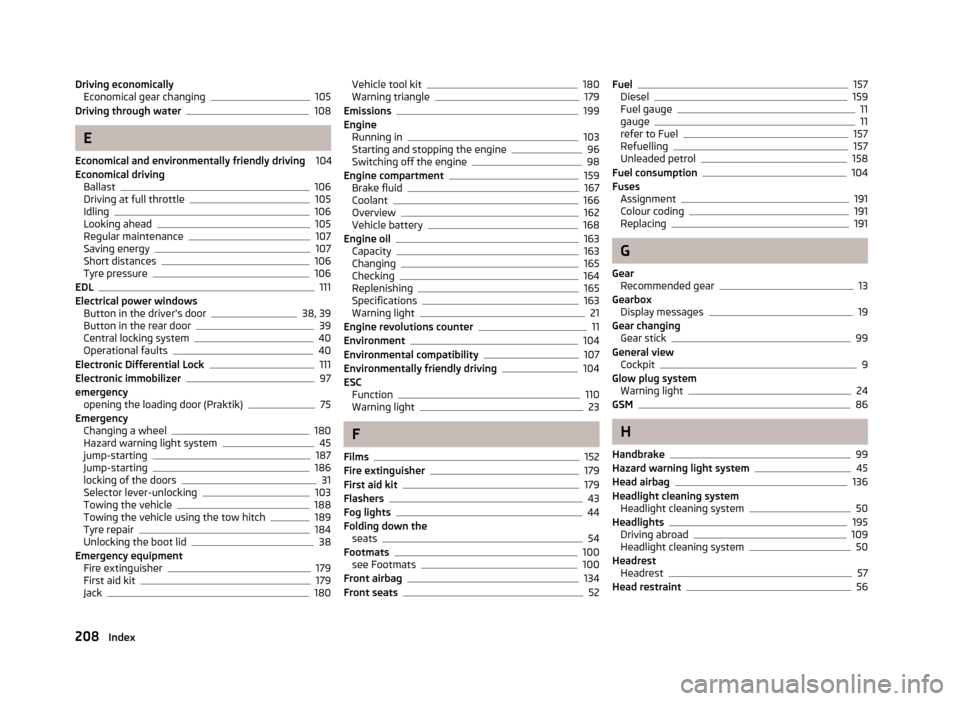
Driving economicallyEconomical gear changing105
Driving through water108
E
Economical and environmentally friendly driving 104
Economical driving Ballast
106
Driving at full throttle105
Idling106
Looking ahead105
Regular maintenance107
Saving energy107
Short distances106
Tyre pressure106
EDL111
Electrical power windows Button in the driver's door
38, 39
Button in the rear door39
Central locking system40
Operational faults40
Electronic Differential Lock111
Electronic immobilizer97
emergency opening the loading door (Praktik)
75
Emergency Changing a wheel
180
Hazard warning light system45
jump-starting187
Jump-starting186
locking of the doors31
Selector lever-unlocking103
Towing the vehicle188
Towing the vehicle using the tow hitch189
Tyre repair184
Unlocking the boot lid38
Emergency equipment Fire extinguisher
179
First aid kit179
Jack180
Vehicle tool kit180
Warning triangle179
Emissions199
Engine Running in
103
Starting and stopping the engine96
Switching off the engine98
Engine compartment159
Brake fluid167
Coolant166
Overview162
Vehicle battery168
Engine oil163
Capacity163
Changing165
Checking164
Replenishing165
Specifications163
Warning light21
Engine revolutions counter11
Environment104
Environmental compatibility107
Environmentally friendly driving104
ESC Function
110
Warning light23
F
Films
152
Fire extinguisher179
First aid kit179
Flashers43
Fog lights44
Folding down the seats
54
Footmats100
see Footmats100
Front airbag134
Front seats52
Fuel157
Diesel159
Fuel gauge11
gauge11
refer to Fuel157
Refuelling157
Unleaded petrol158
Fuel consumption104
Fuses Assignment
191
Colour coding191
Replacing191
G
Gear Recommended gear
13
Gearbox Display messages
19
Gear changing Gear stick
99
General view Cockpit
9
Glow plug system Warning light
24
GSM86
H
Handbrake
99
Hazard warning light system45
Head airbag136
Headlight cleaning system Headlight cleaning system
50
Headlights195
Driving abroad109
Headlight cleaning system50
Headrest Headrest
57
Head restraint56
208Index
Page 215 of 219
TransportBoot57
Roof rack system65
Transporting children safely139
Trays folding table in the middle back seat
72
Turn signals43
Two-way radio systems86
Type plate199
Tyre load-bearing capacity Refer to Wheels
174
Tyre pressure monitor Setting
175
Tyre repair Check pressure
186
Preparations185
Sealing and inflating the tyre185
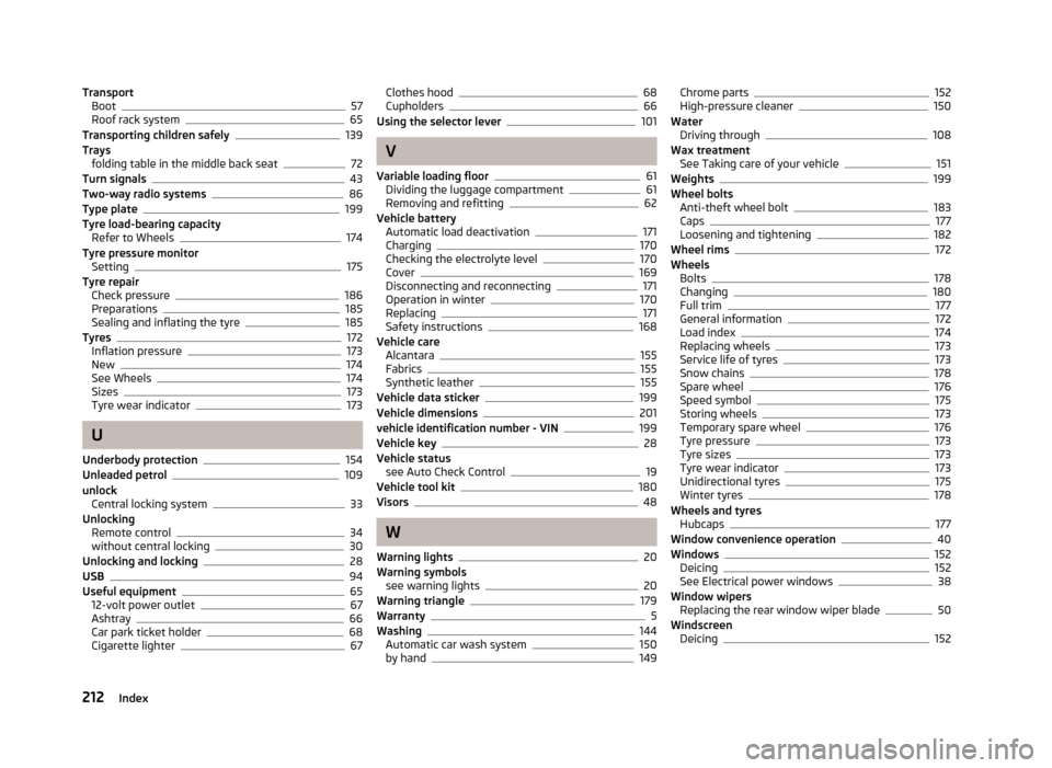
Tyres172
Inflation pressure173
New174
See Wheels174
Sizes173
Tyre wear indicator173
U
Underbody protection
154
Unleaded petrol109
unlock Central locking system
33
Unlocking Remote control
34
without central locking30
Unlocking and locking28
USB94
Useful equipment65
12-volt power outlet67
Ashtray66
Car park ticket holder68
Cigarette lighter67
Clothes hood68
Cupholders66
Using the selector lever101
V
Variable loading floor
61
Dividing the luggage compartment61
Removing and refitting62
Vehicle battery Automatic load deactivation
171
Charging170
Checking the electrolyte level170
Cover169
Disconnecting and reconnecting171
Operation in winter170
Replacing171
Safety instructions168
Vehicle care Alcantara
155
Fabrics155
Synthetic leather155
Vehicle data sticker199
Vehicle dimensions201
vehicle identification number - VIN199
Vehicle key28
Vehicle status see Auto Check Control
19
Vehicle tool kit180
Visors48
W
Warning lights
20
Warning symbols see warning lights
20
Warning triangle179
Warranty5
Washing144
Automatic car wash system150
by hand149
Chrome parts152
High-pressure cleaner150
Water Driving through
108
Wax treatment See Taking care of your vehicle
151
Weights199
Wheel bolts Anti-theft wheel bolt
183
Caps177
Loosening and tightening182
Wheel rims172
Wheels Bolts
178
Changing180
Full trim177
General information172
Load index174
Replacing wheels173
Service life of tyres173
Snow chains178
Spare wheel176
Speed symbol175
Storing wheels173
Temporary spare wheel176
Tyre pressure173
Tyre sizes173
Tyre wear indicator173
Unidirectional tyres175
Winter tyres178
Wheels and tyres Hubcaps
177
Window convenience operation40
Windows152
Deicing152
See Electrical power windows38
Window wipers Replacing the rear window wiper blade
50
Windscreen Deicing
152
212Index