airbag SKODA ROOMSTER 2013 1.G Owner's Manual
[x] Cancel search | Manufacturer: SKODA, Model Year: 2013, Model line: ROOMSTER, Model: SKODA ROOMSTER 2013 1.GPages: 219, PDF Size: 13.83 MB
Page 6 of 219
Table of Contents
Materials defect liability and ŠKODA warranty for
new cars5
Mobility warranty and ŠKODA extended
warranty
6
Abbreviations
Operation
Cockpit
9
Overview
8
Instruments and Indicator Lights
10
Instrument cluster
10
Multifunction display (MFD)
13
Service Interval Display
16
MAXI DOT display
18
Warning lights
20
Unlocking and locking
28
Unlocking and locking
28
Central locking system
31
Remote control
34
Anti-theft alarm system
35
Luggage compartment lid
37
Electrical power windows
38
Lights and visibility
41
Lights
41
Interior lights
46
Visibility
47
Windscreen wipers and washers
48
Rear window
51
Seats and stowing
52
Front seats
52
Rear seats
54Head restraints56Boot57
Variable loading floor in the luggage
compartment (Estate)
61
Bicycle carrier in the luggage compartment
63
Roof rack system
65
Useful equipment
65
Storage compartments
68
Praktik
73
Heating and air-conditioning
77
Heating, ventilation, cooling
77
Heating
78
Air conditioning system (manual air conditioning system)
80
Climatronic (automatic air conditioningsystem)
83
Communication and multimedia
86
Universal telephone preinstallation GSM II
86
Voice control
91
Multimedia
92
Driving
Starting-off and Driving
95
Steering
95
Starting and stopping the engine
96
Brakes
98
Manual gear changing and pedals
99
Automatic transmission
100
Running in
103
Economical driving and environmental
sustainability
104
Avoiding damage to your vehicle
108
Driving abroad
109
Assist systems
110
Brake assist systems
110
Parking aid
112Cruise Control System113START-STOP115
Towing a trailer
117
Towing device
117
Trailer
120
Safety
Passive Safety
123
General information
123
Correct seated position
124
Seat belts
127
Using seat belts
127
Inertia reels and belt tensioners
130
Airbag system
132
Description of the airbag system
132
Airbag overview
133
Deactivating airbags
136
Transporting children safely
139
Child seat
139
Fastening systems
141
General Maintenance
Car care
144
Service intervals
144
Services, modifications and technical
alterations
146
Washing your car
149
Taking care of your vehicle exterior
150
Taking care of the interior
154
Inspecting and replenishing
157
Fuel
157
Engine compartment
159
Engine oil
163
Coolant
1653Table of Contents
Page 12 of 219
Operation
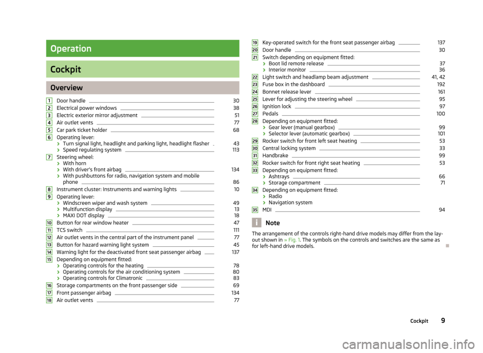
Cockpit
OverviewDoor handle
30
Electrical power windows
38
Electric exterior mirror adjustment
51
Air outlet vents
77
Car park ticket holder
68
Operating lever:
› Turn signal light, headlight and parking light, headlight flasher
43
›
Speed regulating system
113
Steering wheel:
› With horn
› With driver’s front airbag
134
›With pushbuttons for radio, navigation system and mobile
phone
86
Instrument cluster: Instruments and warning lights
10
Operating lever:
› Windscreen wiper and wash system
49
›Multifunction display
13
›
MAXI DOT display
18
Button for rear window heater
47
TCS switch
111
Air outlet vents in the central part of the instrument panel
77
Button for hazard warning light system
45
Warning light for the deactivated front seat passenger airbag
137
Depending on equipment fitted:
› Operating controls for the heating
78
›Operating controls for the air conditioning system
80
›Operating controls for Climatronic
83
Storage compartments on the front passenger side
69
Front passenger airbag
134
Air outlet vents
77123456789101112131415161718Key-operated switch for the front seat passenger airbag137Door handle30
Switch depending on equipment fitted:
› Boot lid remote release
37
›Interior monitor
36
Light switch and headlamp beam adjustment
41, 42
Fuse box in the dashboard
192
Bonnet release lever
161
Lever for adjusting the steering wheel
95
Ignition lock
97
Pedals
100
Depending on equipment fitted:
› Gear lever (manual gearbox)
99
›Selector lever (automatic gearbox)
101
Rocker switch for front left seat heating
53
Central locking system
33
Handbrake
99
Rocker switch for front right seat heating
53
Depending on equipment fitted:
› Ashtrays
66
›Storage compartment
71
Depending on equipment fitted:
› Radio
› Navigation system
MDI
94
Note
The arrangement of the controls right-hand drive models may differ from the lay-
out shown in » Fig. 1. The symbols on the controls and switches are the same as
for left-hand drive models.19202122232425262728293031323334359Cockpit
Page 23 of 219
Note■Warning messages shown in the MAXI DOT display must be confirmed with but-
ton B » Fig. 7 on page 18 to call up the main menu.■
As long as the operational faults are not rectified, the symbols are always indi-
cated again. After they are displayed for the first time, the symbols continue to be
indicated without any extra messages for the driver.
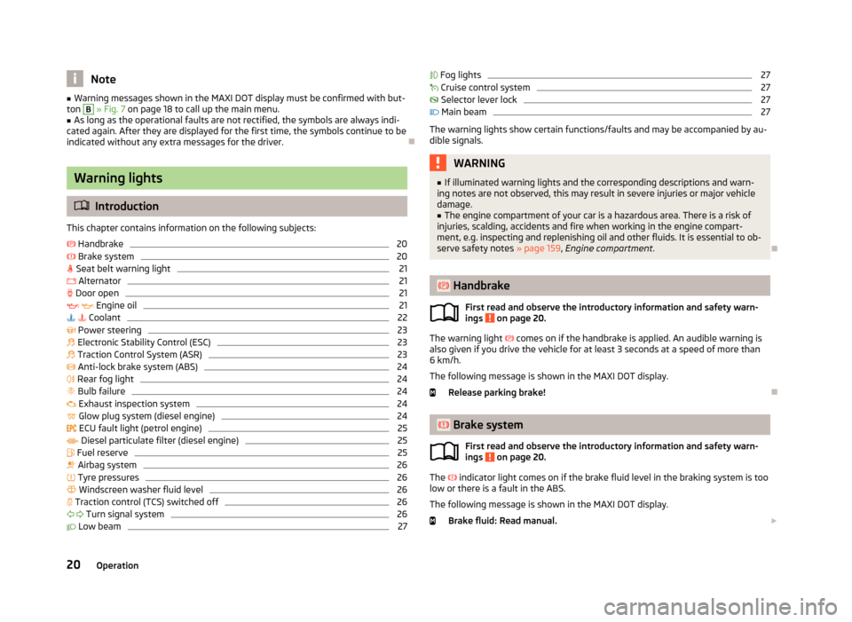
Warning lights
Introduction
This chapter contains information on the following subjects:
Handbrake
20
Brake system
20
Seat belt warning light
21
Alternator
21
Door open
21
Engine oil
21
Coolant
22
Power steering
23
Electronic Stability Control (ESC)
23
Traction Control System (ASR)
23
Anti-lock brake system (ABS)
24
Rear fog light
24
Bulb failure
24
Exhaust inspection system
24
Glow plug system (diesel engine)
24
ECU fault light (petrol engine)
25
Diesel particulate filter (diesel engine)
25
Fuel reserve
25
Airbag system
26
Tyre pressures
26
Windscreen washer fluid level
26
Traction control (TCS) switched off
26
Turn signal system
26
Low beam
27 Fog lights27 Cruise control system27
Selector lever lock
27
Main beam
27
The warning lights show certain functions/faults and may be accompanied by au-
dible signals.
WARNING■ If illuminated warning lights and the corresponding descriptions and warn-
ing notes are not observed, this may result in severe injuries or major vehicle
damage.■
The engine compartment of your car is a hazardous area. There is a risk of
injuries, scalding, accidents and fire when working in the engine compart-
ment, e.g. inspecting and replenishing oil and other fluids. It is essential to ob-
serve safety notes » page 159, Engine compartment .
Handbrake
First read and observe the introductory information and safety warn-
ings
on page 20.
The warning light
comes on if the handbrake is applied. An audible warning is
also given if you drive the vehicle for at least 3 seconds at a speed of more than
6 km/h.
The following message is shown in the MAXI DOT display.
Release parking brake!
Brake system
First read and observe the introductory information and safety warn-
ings
on page 20.
The
indicator light comes on if the brake fluid level in the braking system is too
low or there is a fault in the ABS.
The following message is shown in the MAXI DOT display. Brake fluid: Read manual.
20Operation
Page 29 of 219
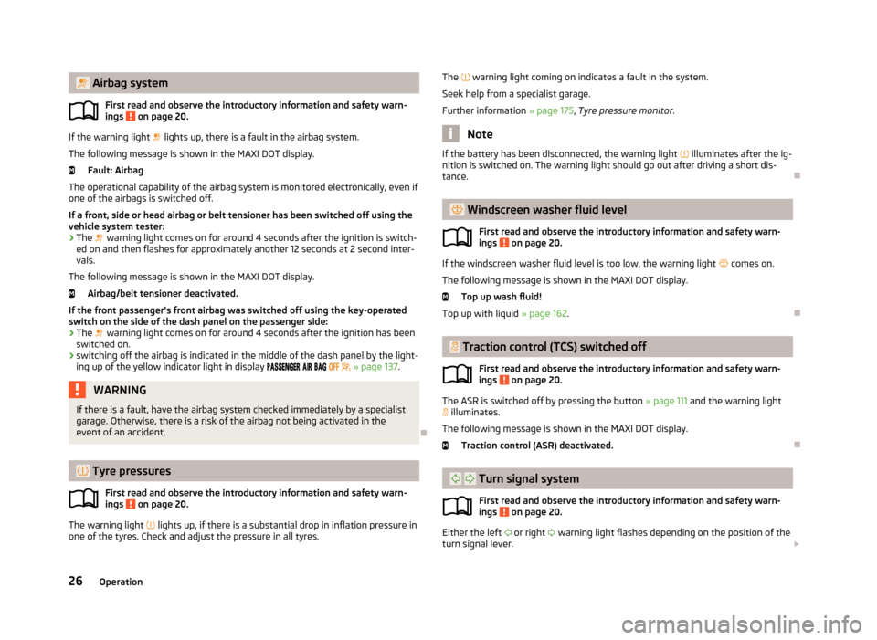
Airbag systemFirst read and observe the introductory information and safety warn-ings
on page 20.
If the warning light lights up, there is a fault in the airbag system.
The following message is shown in the MAXI DOT display. Fault: Airbag
The operational capability of the airbag system is monitored electronically, even if one of the airbags is switched off.
If a front, side or head airbag or belt tensioner has been switched off using the vehicle system tester:
› The
warning light comes on for around 4 seconds after the ignition is switch-
ed on and then flashes for approximately another 12 seconds at 2 second inter-
vals.
The following message is shown in the MAXI DOT display.
Airbag/belt tensioner deactivated.
If the front passenger's front airbag was switched off using the key-operated
switch on the side of the dash panel on the passenger side:
› The
warning light comes on for around 4 seconds after the ignition has been
switched on.
› switching off the airbag is indicated in the middle of the dash panel by the light-
ing up of the yellow indicator light in display
» page 137 .
WARNINGIf there is a fault, have the airbag system checked immediately by a specialist
garage. Otherwise, there is a risk of the airbag not being activated in the
event of an accident.
Tyre pressures
First read and observe the introductory information and safety warn-
ings
on page 20.
The warning light
lights up, if there is a substantial drop in inflation pressure in
one of the tyres. Check and adjust the pressure in all tyres.
The warning light coming on indicates a fault in the system.
Seek help from a specialist garage.
Further information » page 175, Tyre pressure monitor .
Note
If the battery has been disconnected, the warning light illuminates after the ig-
nition is switched on. The warning light should go out after driving a short dis-
tance.
Windscreen washer fluid level
First read and observe the introductory information and safety warn-ings
on page 20.
If the windscreen washer fluid level is too low, the warning light
comes on.
The following message is shown in the MAXI DOT display. Top up wash fluid!
Top up with liquid » page 162.
Traction control (TCS) switched off
First read and observe the introductory information and safety warn-ings
on page 20.
The ASR is switched off by pressing the button » page 111 and the warning light
illuminates.
The following message is shown in the MAXI DOT display.
Traction control (ASR) deactivated.
Turn signal system
First read and observe the introductory information and safety warn-ings
on page 20.
Either the left
or right
warning light flashes depending on the position of the
turn signal lever.
26Operation
Page 35 of 219
CAUTIONIf the safe securing system is activated» page 32, the door opening lever and
the central locking buttons do not operate.
Note
■ In the event of an accident in which the airbags are deployed, the locked doors
are automatically unlocked in order to enable rescuers to gain access to the vehi- cle.■
Only the driver's door can be locked or unlocked with the key if the central lock-
ing system fails. The other doors and the tailgate can be locked or unlocked man-
ually. ■ Emergency locking of the door » page 31.
■ Emergency unlocking of the boot lid » page 38.
Individual settings
First read and observe the introductory information and safety warn-
ings
on page 31.
Opening a single door
This selection function makes it possible to only unlock the driver's door. The oth-
er doors remain locked and are only unlocked when the command is repeated.
Automatic locking and unlocking
All the doors and the boot lid are locked automatically once the car reaches a
speed of about 15 km/h.
If the ignition key is withdrawn, the car is then automatically unlocked again. In addition, it is possible for the driver or front passenger to unlock the car by press-
ing the central locking button
» page 33 .
The doors can be unlocked and opened from the inside by pulling on the opening lever of the respective door. By the first pull on the opening lever, the door is un-
locked . By the second pull on the opening lever, the door is opened.
Note
Individual settings can be applied in a specialist workshop.
Safe securing
First read and observe the introductory information and safety warn-
ings
on page 31.
The central locking system is equipped with a safe securing system. The door
locks are blocked automatically if the vehicle is locked from the outside. The warning light flashes for around 2 seconds in quick succession, afterwards it be-gins to flash evenly at longer intervals. It is not possible to open the doors withthe door handle either from the inside or from the outside. This acts as an effec-
tive deterrent for attempts to break into your vehicle.
The safe securing system can be deactivated within 2 seconds by double locking
the vehicle.
If the safe securing system is not operating, the warning light in the driver door flashes for about 2 seconds fast, goes out and starts to flash evenly at longer in-
tervals after about 30 seconds.
The safe securing system is activated again the next time the vehicle is unlocked and locked.
If the vehicle is locked and the safe securing system is deactivated, the door can
be unlocked and opened from the inside by pulling on the opening lever of the respective door. By the first pull on the opening lever, the door is unlocked. By
the second pull on the opening lever, the door is opened.
WARNINGIf the vehicle is locked from the outside and the safe securing system is acti-
vated, there must not be any person in the vehicle as it is then no longer pos-
sible to open either a door or a window from the inside. The locked doors
make it more difficult for rescuers to get into the vehicle in an emergency –
risk to life!
Note
■ The anti-theft alarm system is activated when the vehicle is locked even if the
safe securing system is deactivated. The interior monitor is however not activa- ted.■
You will be informed that the safe securing system is activated after the vehicle
is locked by the CHECK DEADLOCK message on the instrument cluster display. On
vehicles equipped with the MAXI DOT display, the display shows Check deadlock.
Read manual.
32Operation
Page 37 of 219
The following applies if your vehicle has been locked using the central lockingbutton.
› It is not possible to open the doors or the boot lid from the outside (safety fea-
ture, e.g. when stopping at traffic lights etc.).
› The doors can be unlocked and opened from the inside by pulling on the open-
ing lever of the respective door. By the first pull on the opening lever, the door is unlocked . By the second pull on the opening lever, the door is opened.
› If at least one door has been opened, the vehicle cannot be locked.
› In the event of an accident in which the airbags are deployed, the locked doors
are automatically unlocked from the inside in order to enable rescuers to gain access to the vehicle.
Remote control
Introduction
This chapter contains information on the following subjects:
Unlocking/locking
34
Synchronization
35
You can use the remote control key to:
› unlock and lock the vehicle,
› unlocking boot lid;
› open and close the windows
» page 40, Window convenience operation .
The transmitter with the battery is housed in the handle of the remote control
key. The receiver is located in the interior of the vehicle. The operating range of
the remote control key is approx. 30 m. But this range of the remote control can
be reduced if the batteries are weak.
The key has a fold-open key bit which can be used for unlocking and locking the
car manually and also for starting the engine.
If a lost key is replaced or if the receiver unit has been repaired or replaced, the
system must be initialised by a specialist garage. Only then can the remote con-
trol key be used again.
Note■ The remote control is automatically deactivated when the ignition is switched
on.■
The operation of the remote control may temporarily be affected by interfer-
ence from transmitters close to the car and which operate in the same frequency
range (e.g. mobile phone, TV transmitter).
■
The battery must be replaced if the central locking or anti-theft alarm system
does react to the remote control at less than 3 metres away » page 29.
■
If the driver door is open, the vehicle cannot be locked using the remote control
key.
Unlocking/locking
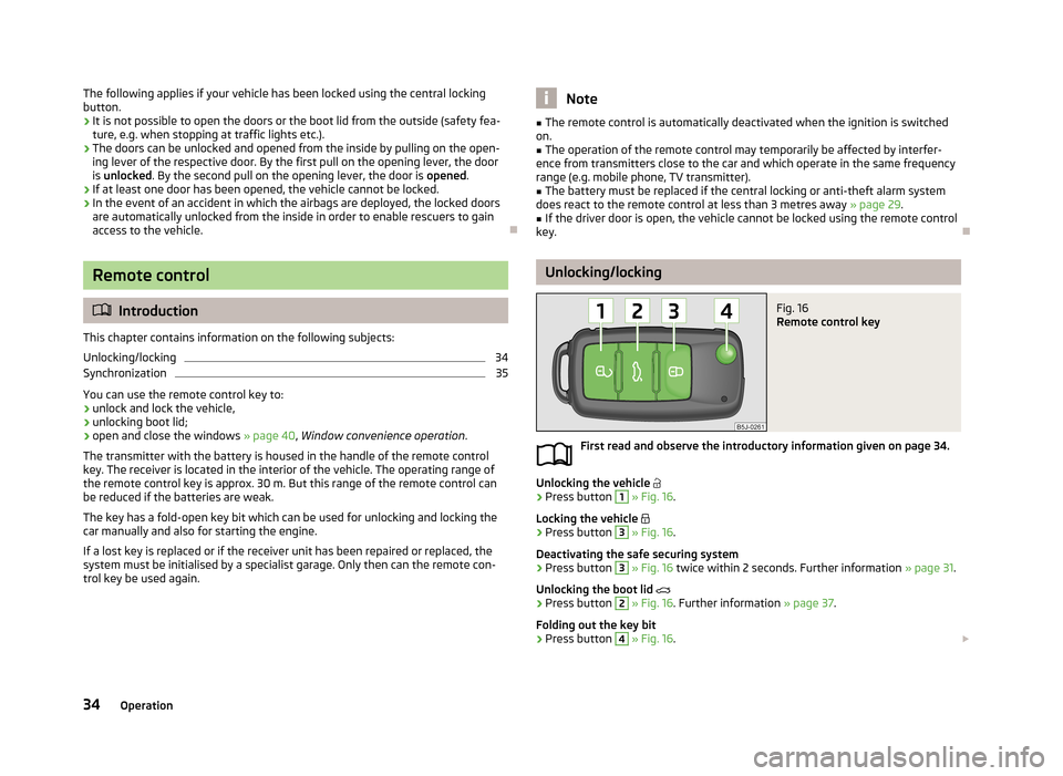
Fig. 16
Remote control key
First read and observe the introductory information given on page 34.
Unlocking the vehicle
›
Press button
1
» Fig. 16 .
Locking the vehicle
›
Press button
3
» Fig. 16 .
Deactivating the safe securing system
›
Press button
3
» Fig. 16 twice within 2 seconds. Further information » page 31.
Unlocking the boot lid
›
Press button
2
» Fig. 16 . Further information » page 37.
Folding out the key bit
›
Press button
4
» Fig. 16 .
34Operation
Page 48 of 219
Ignition switched off, light switched off (light switch in position 0), control dial for
headlamp beam adjustment in the position, no gear engaged or selector lever
in the N position (automatic gearbox), tourist light deactivated.›
Switch on the ignition.
Within 10 seconds of the ignition being switched on:
›
Turn the light switch to the position » page 41 , Parking and low beam lights .
›
Engage reverse gear (manual gearbox) or move the selector lever to the R posi-
tion (automatic gearbox),
›
Turn the headlamp beam adjustment dial from to » page 42 .
Deactivating tourist light
Before deactivating the tourist light, the following conditions must be met.
Ignition switched off, light switched off (light switch in position 0), control dial for
headlamp beam adjustment in the
position, no gear engaged or selector lever in
the N position (automatic gearbox), tourist light activated.
›
Switch on the ignition.
Within 10 seconds of the ignition being switched on:
›
Turn the light switch to the
position » page 41 , Parking and low beam lights .
›
Engage reverse gear (manual gearbox) or move the selector lever to the R posi-
tion (automatic gearbox),
›
Turn the headlamp beam adjustment dial from
to
» page 42 .
Further information » page 109, Headlights .
Note
When the “tourist light” mode is active, the warning light flashes for 10 sec-
onds each time the ignition is switched on.
Hazard warning light systemFig. 25
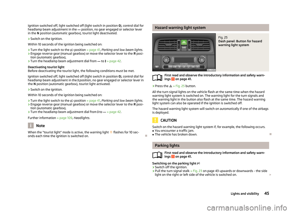
Dash panel: Button for hazard
warning light system
First read and observe the introductory information and safety warn-
ings on page 41.
›
Press the
» Fig. 25 button.
All the turn signal lights on the vehicle flash at the same time when the hazard
warning light system is switched on. The warning light for the turn signals and
the warning light in the button also flash at the same time. The hazard warning
light system can also be operated if the ignition is switched off.
The hazard warning light system will switch on automatically if one of the airbags
is deployed.
CAUTION
Switch on the hazard warning light system if, for example, the following occurs.■You encounter a traffic jam.■
The vehicle has broken down.
Parking lights
First read and observe the introductory information and safety warn-ings
on page 41.
Switching on the parking light
›
Switch off the ignition.
›
Pull the turn signal stalk
» Fig. 23 on page 43 upwards or downwards - the side
light on the right or left side of the vehicle is switched on.
45Lights and visibility
Page 51 of 219
Sun visorsFig. 29
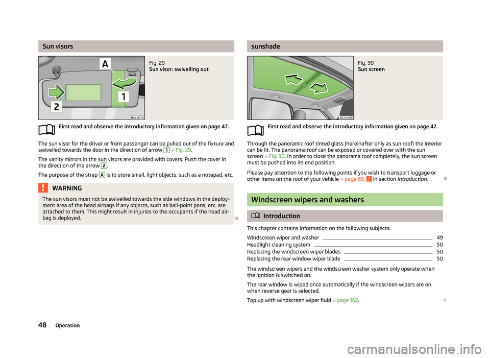
Sun visor: swivelling out
First read and observe the introductory information given on page 47.
The sun visor for the driver or front passenger can be pulled out of the fixture and
swivelled towards the door in the direction of arrow
1
» Fig. 29 .
The vanity mirrors in the sun visors are provided with covers. Push the cover in the direction of the arrow
2
.
The purpose of the strap
A
is to store small, light objects, such as a notepad, etc.
WARNINGThe sun visors must not be swivelled towards the side windows in the deploy-
ment area of the head airbags if any objects, such as ball-point pens, etc. are attached to them. This might result in injuries to the occupants if the head air-
bag is deployed.
sunshadeFig. 30
Sun screen
First read and observe the introductory information given on page 47.
Through the panoramic roof tinted glass (hereinafter only as sun roof) the interior can be lit. The panorama roof can be exposed or covered over with the sun
screen » Fig. 30 . In order to close the panorama roof completely, the sun screen
must be pushed into its end position.
Please pay attention to the following points if you wish to transport luggage or other items on the roof of your vehicle » page 65,
in section Introduction .
Windscreen wipers and washers
Introduction
This chapter contains information on the following subjects:
Windscreen wiper and washer
49
Headlight cleaning system
50
Replacing the windscreen wiper blades
50
Replacing the rear window wiper blade
50
The windscreen wipers and the windscreen washer system only operate when
the ignition is switched on.
The rear window is wiped once automatically if the windscreen wipers are on when reverse gear is selected.
Top up with windscreen wiper fluid » page 162.
48Operation
Page 55 of 219
Seats and stowing
Front seats
Introduction
This chapter contains information on the following subjects:
Adjusting the front seats
53
Front seat heating
53
The driver's seat should be adjusted in such a way that the pedals can be fully
pressed to the floor with slightly bent legs.
The seat backrest on the driver's seat should be adjusted in such a way that the
upper point of the steering wheel can be easily reached with slightly bent arms.
Correct adjustment of the seats is particularly important:
› for safely and quickly reaching the controls;
› for a relaxed body position that reduces fatigue;
› for achieving maximum protection from the seat belts and the airbag system.
WARNINGGeneral information■Caution when adjusting the seat! You may suffer injuries or bruises as a re-
sult of adjusting the seat without paying proper attention.■
The seat backrests must not be tilted too far back when driving, as this will
impair the function of the seat belts and of the airbag system – risk of injury!
■
Never carry more people than the number of seats in the vehicle.
■
Each occupant must correctly fasten the seat belt belonging to the seat.
Children must be fastened » page 139, Transporting children safely with a
suitable restraint system.
■
The front seats and head restraints must be adjusted to match the body
size at all times and the seat belt must always be fastened properly to provide
the most effective levels of protection to the passengers.
■
Do not carry any objects on the front passenger seat except objects de-
signed for this purpose (e.g. child seat) – risk of accident!
WARNINGInformation for the driver■Only adjust the driver's seat when the vehicle is stationary – risk of accident!■
Maintain a distance of at least 25 cm to the steering wheel. Not maintaining
this minimum distance will mean that the airbag system will not be able to
properly protect you – hazard!
■
Ensure that there are no objects in the driver's footwell, as these may get
caught in the pedal apparatus when driving or braking. You would then no
longer be able to operate the clutch, brake or acceleration pedals.
WARNINGInformation for the front seat passenger■Maintain a distance of at least 25 cm from the dash panel. Not maintaining
this minimum distance will mean that the airbag system will not be able to
properly protect you - there is a risk that you could be killed.■
Always keep your feet in the footwell when the car is being driven - never
place your feet on the instrument panel, out of the window or on the seats.
You will be exposed to increased risk of injury if it becomes necessary to apply
the brakes or in the event of an accident. You may suffer fatal injuries when
an airbag is deployed if you have adopted an incorrect seating position.
Note
After a certain time, play can develop within the adjustment mechanism of the
backrest angle.
52Operation
Page 60 of 219
WARNING■The head restraints must be correctly adjusted in order to offer effective
protection for the occupants in the event of an accident.■
Never drive with the head restraints removed - risk of injury.
■
If the rear seats are occupied, the rear head restraint must not be in the
lower position.
headrest adjust
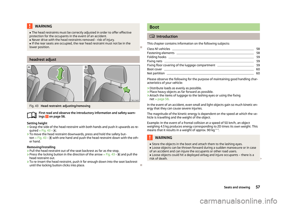
Fig. 43
Head restraint: adjusting/removing
First read and observe the introductory information and safety warn- ings
on page 56.
Setting height
›
Grasp the side of the head restraint with both hands and push it upwards as re-
quired » Fig. 43 -
.
›
To move the head restraint downwards, press and hold the safety but-
ton » Fig. 43 -
with one hand and push the head restraint down with the oth-
er hand.
Removing/installing
›
Pull the head restraint out of the seat backrest as far as the stop.
›
Press the locking button in the direction of the arrow » Fig. 43 -
and pull the
head restraint out.
›
To re-insert the head restraint, push it far enough down into the seat backrest until the locking button clicks into place.
Boot
Introduction
This chapter contains information on the following subjects:
Class N1 vehicles
58
Fastening elements
58
Folding hooks
59
Fixing nets
59
Fixing floor covering of the luggage compartment
59
Boot cover
60
Net partition
60
Please observe the following for the purpose of maintaining good handling char-
acteristics of your vehicle:
›
Distribute loads as evenly as possible.
›
Place heavy objects as far forward as possible.
›
Attach the items of luggage to the lashing eyes or using the fixing net » page 58 .
In the event of an accident, even small and light objects gain so much kinetic en-
ergy that they can cause severe injuries.
The magnitude of the kinetic energy is dependent on the speed at which the ve-
hicle is travelling and the weight of the object.
Example: In the event of a frontal collision at a speed of 50 km/h, an object
weighing 4.5 kg produces energy corresponding to 20 times its own weight. This
means that it results in a weight of approx. 90 kg “ ”.
WARNING■ Store the objects in the boot and attach them to the lashing eyes.■Loose objects can be thrown forward during a sudden manoeuvre or in case
of an accident and can injure the occupants or other road users.■
Loose objects could hit a deployed airbag and injure occupants – there is a
risk of death.
57Seats and stowing