dashboard SKODA ROOMSTER 2013 1.G Owner's Manual
[x] Cancel search | Manufacturer: SKODA, Model Year: 2013, Model line: ROOMSTER, Model: SKODA ROOMSTER 2013 1.GPages: 219, PDF Size: 13.83 MB
Page 12 of 219

Operation
Cockpit
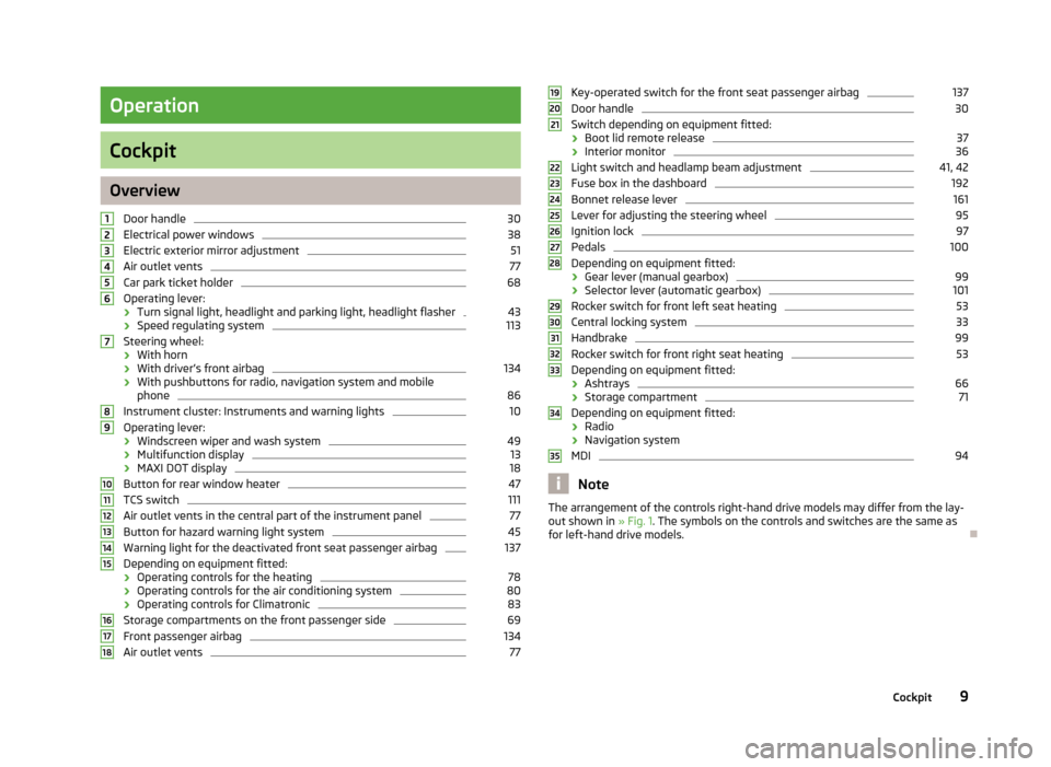
OverviewDoor handle
30
Electrical power windows
38
Electric exterior mirror adjustment
51
Air outlet vents
77
Car park ticket holder
68
Operating lever:
› Turn signal light, headlight and parking light, headlight flasher
43
›
Speed regulating system
113
Steering wheel:
› With horn
› With driver’s front airbag
134
›With pushbuttons for radio, navigation system and mobile
phone
86
Instrument cluster: Instruments and warning lights
10
Operating lever:
› Windscreen wiper and wash system
49
›Multifunction display
13
›
MAXI DOT display
18
Button for rear window heater
47
TCS switch
111
Air outlet vents in the central part of the instrument panel
77
Button for hazard warning light system
45
Warning light for the deactivated front seat passenger airbag
137
Depending on equipment fitted:
› Operating controls for the heating
78
›Operating controls for the air conditioning system
80
›Operating controls for Climatronic
83
Storage compartments on the front passenger side
69
Front passenger airbag
134
Air outlet vents
77123456789101112131415161718Key-operated switch for the front seat passenger airbag137Door handle30
Switch depending on equipment fitted:
› Boot lid remote release
37
›Interior monitor
36
Light switch and headlamp beam adjustment
41, 42
Fuse box in the dashboard
192
Bonnet release lever
161
Lever for adjusting the steering wheel
95
Ignition lock
97
Pedals
100
Depending on equipment fitted:
› Gear lever (manual gearbox)
99
›Selector lever (automatic gearbox)
101
Rocker switch for front left seat heating
53
Central locking system
33
Handbrake
99
Rocker switch for front right seat heating
53
Depending on equipment fitted:
› Ashtrays
66
›Storage compartment
71
Depending on equipment fitted:
› Radio
› Navigation system
MDI
94
Note
The arrangement of the controls right-hand drive models may differ from the lay-
out shown in » Fig. 1. The symbols on the controls and switches are the same as
for left-hand drive models.19202122232425262728293031323334359Cockpit
Page 125 of 219

Note■After coupling the trailer and connecting up the power socket, check the rear
lights on the trailer to ensure they work.■
If there is an error in the trailer lighting system, check the fuses in the fuse box
in the dashboard » page 192.
■
If you tow a trailer frequently, you should also have your car inspected between
service intervals.
■
The handbrake on the towing vehicle must be applied when coupling and un-
coupling the trailer.
Anti-theft alarm system
First read and observe the introductory information and safety warn-
ings
on page 120.
When the vehicle is locked, the alarm is activated as soon as the electrical con- nection to the trailer is interrupted.
Always switch off the anti-theft alarm system before a trailer is coupled or uncou- pled » page 35 .
Conditions for including a trailer in the anti-theft alarm system. The vehicle is factory-fitted with an anti-theft alarm system and towingequipment.
The trailer is electrically connected to the towing vehicle by means of the
trailer socket.
The electrical system of the vehicle and trailer is functional. The vehicle is locked with the vehicle key and the anti-theft alarm system isactivated.
Note
For technical reasons, trailers with rear LED lights cannot be connected to the an-
ti-theft alarm system.
122Driving
Page 137 of 219

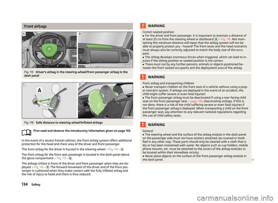
Front airbagsFig. 115
Driver's airbag in the steering wheel/front passenger airbag in the
dash panel
Fig. 116
Safe distance to steering wheel/inflated airbags
First read and observe the introductory information given on page 133.
In the event of a severe frontal collision, the front airbag system offers additional
protection for the head and chest area of the driver and front passenger.
The front airbag for the driver is housed in the steering wheel » Fig. 115 -
.
The front airbag for the front seat passenger is located in the dash panel above
the glove compartment » Fig. 115 -
.
The airbags inflate in front of the driver and front passenger when they are de- ployed » Fig. 116 -
. The forward movement of the driver and of the front pas-
senger is cushioned when they make contact with the fully inflated airbag and
the risk of injury to head and chest is thus reduced.
WARNINGCorrect seated position■For the driver and front passenger, it is important to maintain a distance of
at least 25 cm from the steering wheel or dashboard A
» Fig. 116 . Not main-
taining this minimum distance will mean that the airbag system will not be
able to properly protect you - hazard! The front seats and the head restraints
must always also be correctly adjusted to match the body size of the occu-
pant.
■
The airbag develops enormous forces when triggered, which can lead to in-
juries if the sitting position or seated position is not correct.
■
There must not by any further persons, animals or objects positioned be-
tween the front seated occupants and the deployment area of the airbag.
WARNINGFront airbag and transporting children■Never transport children on the front seat of a vehicle without using a prop-
er restraint system. If airbags are deployed in the event of an accident, the
child might suffer severe or even fatal injuries!■
The front passenger airbag must be deactivated if using a rear-facing child
seat on the front passenger seat » page 136, Deactivating airbags . If this is
not done, there is a risk of the child suffering severe or even fatal injuries if
the front passenger airbag is deployed. When transporting a child on the front
passenger seat, pay attention to any relevant national regulations regarding
the use of child safety seats.
WARNINGGeneral■The steering wheel and the surface of the airbag module in the dash panel
on the passenger side must not have stickers attached, be covered or modi-
fied in any other way. These parts should only be cleaned with a cloth that is
dry or has been moistened with water. No objects such as cup holders, mobile
phone mounts, etc. must be attached to the covers of the airbag modules or
be located within their immediate vicinity.■
Never place objects on the surface of the front passenger airbag module in
the dash panel.
134Safety
Page 188 of 219

Breakdown kitFig. 148
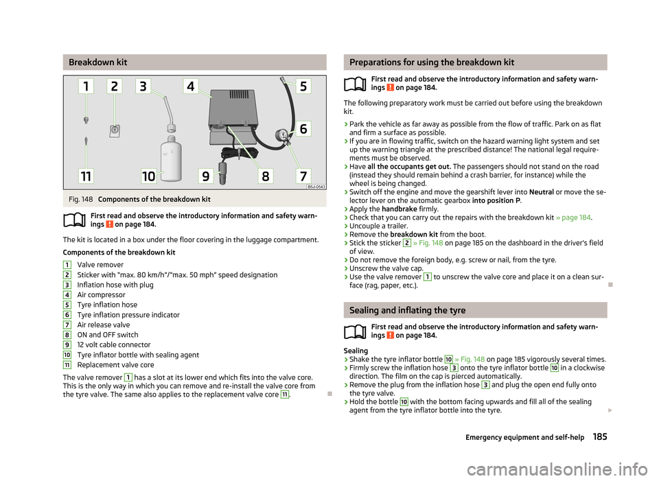
Components of the breakdown kit
First read and observe the introductory information and safety warn-
ings
on page 184.
The kit is located in a box under the floor covering in the luggage compartment.
Components of the breakdown kit Valve remover
Sticker with “max. 80 km/h”/“max. 50 mph” speed designation
Inflation hose with plug
Air compressor
Tyre inflation hose
Tyre inflation pressure indicator
Air release valve
ON and OFF switch
12 volt cable connector
Tyre inflator bottle with sealing agent
Replacement valve core
The valve remover
1
has a slot at its lower end which fits into the valve core.
This is the only way in which you can remove and re-install the valve core from
the tyre valve. The same also applies to the replacement valve core
11
.
1234567891011Preparations for using the breakdown kit
First read and observe the introductory information and safety warn-
ings
on page 184.
The following preparatory work must be carried out before using the breakdown
kit.
›
Park the vehicle as far away as possible from the flow of traffic. Park on as flat and firm a surface as possible.
›
If you are in flowing traffic, switch on the hazard warning light system and setup the warning triangle at the prescribed distance! The national legal require-
ments must be observed.
›
Have all the occupants get out. The passengers should not stand on the road
(instead they should remain behind a crash barrier, for instance) while the wheel is being changed.
›
Switch off the engine and move the gearshift lever into Neutral or move the se-
lector lever on the automatic gearbox into position P.
›
Apply the handbrake firmly.
›
Check that you can carry out the repairs with the breakdown kit » page 184.
›
Uncouple a trailer.
›
Remove the breakdown kit from the boot.
›
Stick the sticker
2
» Fig. 148 on page 185 on the dashboard in the driver's field
of view.
›
Do not remove the foreign body, e.g. screw or nail, from the tyre.
›
Unscrew the valve cap.
›
Use the valve remover
1
to unscrew the valve core and place it on a clean sur-
face (rag, paper, etc.).
Sealing and inflating the tyre
First read and observe the introductory information and safety warn-
ings
on page 184.
Sealing
›
Shake the tyre inflator bottle
10
» Fig. 148 on page 185 vigorously several times.
›
Firmly screw the inflation hose
3
onto the tyre inflator bottle
10
in a clockwise
direction. The film on the cap is pierced automatically.
›
Remove the plug from the inflation hose
3
and plug the open end fully onto
the tyre valve.
›
Hold the bottle
10
with the bottom facing upwards and fill all of the sealing
agent from the tyre inflator bottle into the tyre.
185Emergency equipment and self-help