service indicator SKODA ROOMSTER 2013 1.G Owner's Manual
[x] Cancel search | Manufacturer: SKODA, Model Year: 2013, Model line: ROOMSTER, Model: SKODA ROOMSTER 2013 1.GPages: 219, PDF Size: 13.83 MB
Page 6 of 219
Table of Contents
Materials defect liability and ŠKODA warranty for
new cars5
Mobility warranty and ŠKODA extended
warranty
6
Abbreviations
Operation
Cockpit
9
Overview
8
Instruments and Indicator Lights
10
Instrument cluster
10
Multifunction display (MFD)
13
Service Interval Display
16
MAXI DOT display
18
Warning lights
20
Unlocking and locking
28
Unlocking and locking
28
Central locking system
31
Remote control
34
Anti-theft alarm system
35
Luggage compartment lid
37
Electrical power windows
38
Lights and visibility
41
Lights
41
Interior lights
46
Visibility
47
Windscreen wipers and washers
48
Rear window
51
Seats and stowing
52
Front seats
52
Rear seats
54Head restraints56Boot57
Variable loading floor in the luggage
compartment (Estate)
61
Bicycle carrier in the luggage compartment
63
Roof rack system
65
Useful equipment
65
Storage compartments
68
Praktik
73
Heating and air-conditioning
77
Heating, ventilation, cooling
77
Heating
78
Air conditioning system (manual air conditioning system)
80
Climatronic (automatic air conditioningsystem)
83
Communication and multimedia
86
Universal telephone preinstallation GSM II
86
Voice control
91
Multimedia
92
Driving
Starting-off and Driving
95
Steering
95
Starting and stopping the engine
96
Brakes
98
Manual gear changing and pedals
99
Automatic transmission
100
Running in
103
Economical driving and environmental
sustainability
104
Avoiding damage to your vehicle
108
Driving abroad
109
Assist systems
110
Brake assist systems
110
Parking aid
112Cruise Control System113START-STOP115
Towing a trailer
117
Towing device
117
Trailer
120
Safety
Passive Safety
123
General information
123
Correct seated position
124
Seat belts
127
Using seat belts
127
Inertia reels and belt tensioners
130
Airbag system
132
Description of the airbag system
132
Airbag overview
133
Deactivating airbags
136
Transporting children safely
139
Child seat
139
Fastening systems
141
General Maintenance
Car care
144
Service intervals
144
Services, modifications and technical
alterations
146
Washing your car
149
Taking care of your vehicle exterior
150
Taking care of the interior
154
Inspecting and replenishing
157
Fuel
157
Engine compartment
159
Engine oil
163
Coolant
1653Table of Contents
Page 13 of 219
Instruments and Indicator Lights
Instrument cluster
Introduction
This chapter contains information on the following subjects:
Overview
10
Engine revolutions counter
11
Speedometer
11
Coolant temperature gauge display
11
Fuel gauge
11
Counter for distance driven
12
Digital clock
12
Display of the second speed
12
Recommended gear
13
Fault display
The Error message will appear in the display if there is a fault in the instrument
cluster. Ensure that the fault is rectified as soon as possible by a specialist work-
shop.
WARNING■ Concentrate fully at all times on your driving! As the driver you are fully re-
sponsible for road safety.■
Never operate the controls in the instrument cluster while driving, only
when the vehicle is stationary!
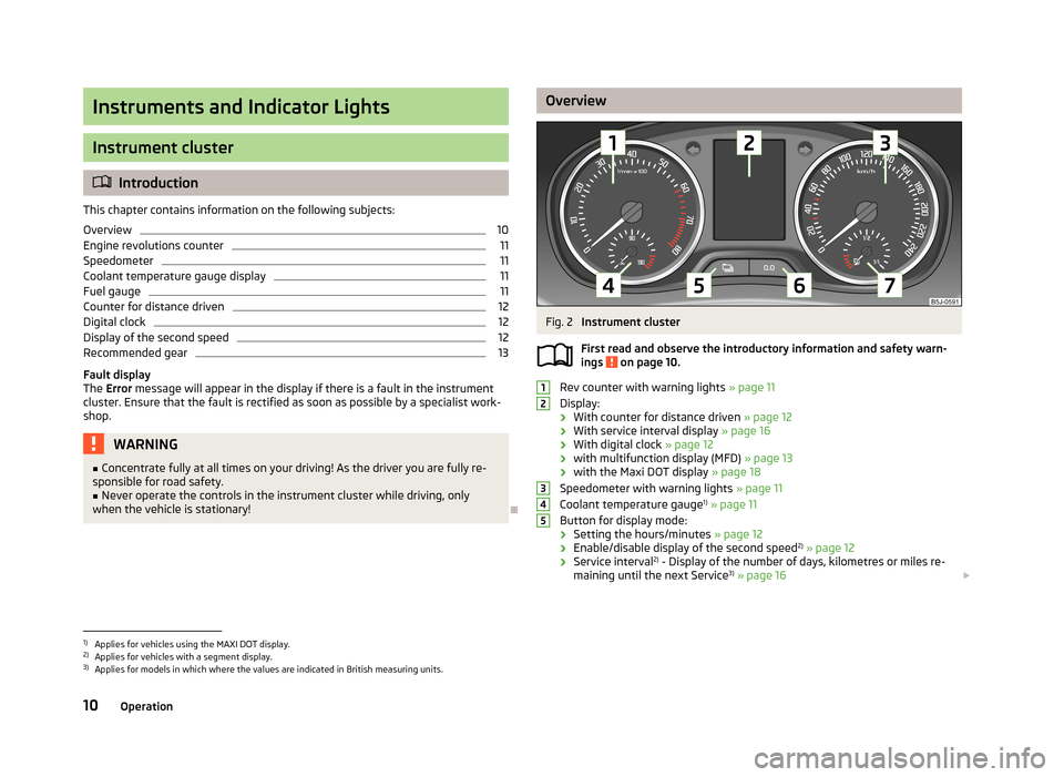
OverviewFig. 2
Instrument cluster
First read and observe the introductory information and safety warn-
ings
on page 10.
Rev counter with warning lights » page 11
Display:
› With counter for distance driven
» page 12
› With service interval display
» page 16
› With digital clock
» page 12
› with multifunction display (MFD)
» page 13
› with the Maxi DOT display
» page 18
Speedometer with warning lights » page 11
Coolant temperature gauge 1)
» page 11
Button for display mode:
› Setting the hours/minutes
» page 12
› Enable/disable display of the second speed 2)
» page 12
› Service interval 2)
- Display of the number of days, kilometres or miles re-
maining until the next Service 3)
» page 16
123451)
Applies for vehicles using the MAXI DOT display.
2)
Applies for vehicles with a segment display.
3)
Applies for models in which where the values are indicated in British measuring units.
10Operation
Page 19 of 219
Current speed
The current speed, identical to the display on the speedometer 3 » Fig. 2 on
page 10, is displayed.
Oil temperature 1)
The current engine oil temperature is displayed. If the oil temperature is lower
than 50 °C or if a fault in the system for checking the oil temperature is present, only - -.- is displayed instead of the oil temperature.
Warning against speeding
The warning that the speed limit is being exceeded can be enabled/disabled in
the display » page 16.
Warning against speeding
First read and observe the introductory information and safety warn-
ings
on page 13.
Adjust the speed limit while the vehicle is stationary
›
Press button
A
» Fig. 5 on page 14 to select the Warning at (MAXI DOT display)
or
(segment display) menu item.
›
Press button
B
to activate the ability to set the speed limit 2)
(value flashes).
›
Use button
A
to set the required speed limit, e.g. 50 km/h.
›
Confirm the speed limit that was set with button
B
, or wait approx. 5 seconds
until the setting is saved automatically (the value stops flashing).
This allows you to set the speed in 5 km/h intervals.
Adjusting the speed limit while the vehicle is moving
›
Press button
A
» Fig. 5 on page 14 to select the Warning at (MAXI DOT display)
or
(segment display) menu item.
›
Drive at the desired speed, e.g. 50 km/h.
›
Press button
B
to accept the current speed as the speed limit (the value flash-
es).
If you wish to adjust the set speed limit, you can do so in 5 km/h intervals (e.g. the
accepted speed of 47 km/h increases to 50 km/h or decreases to 45 km/h).
›
Confirm the speed limit that was set by pressing button
B
again, or wait ap-
prox. 5 seconds until the setting is saved automatically (the value stops flash- ing).
Change or delete speed limit›Press button A » Fig. 5 on page 14 to select the Warning at (MAXI DOT display)
or (segment display) menu item.›
Pressing button
B
disables the speed limit.
›
Pressing the button
B
activates the ability to change the speed limit.
If the set speed limit is exceeded, an audible signal will sound as a warning. The
Warning at (MAXI DOT display) or (segment display) menu item appears in the
display with the limit set.
The speed limit set mode is stored even after the ignition is switched off and on.
Service Interval Display
Introduction
This chapter contains information on the following subjects:
Prompt in the segment display
17
Display in the MAXI DOT display
17
Before the next service interval is reached, a message concerning the kilometres
and days remaining until the next service is due is shown for about 10 seconds
after the ignition is switched on.
The kilometre indicator or the days indicator reduces in steps of 100 km or days until the service due date is reached.
Note
■ Information is retained in the Service Interval Display even after the vehicle bat-
tery is disconnected.■
If the instrument cluster is exchanged after a repair, the correct values must be
entered in the counter for the Service Interval Display. This work is carried out by a specialist garage.
■
For more information on the service intervals » page 144, Service intervals .
1)
Applies for vehicles using the MAXI DOT display.
2)
An initial value of 30 km/h is displayed automatically if no value has been specified.
16Operation
Page 20 of 219
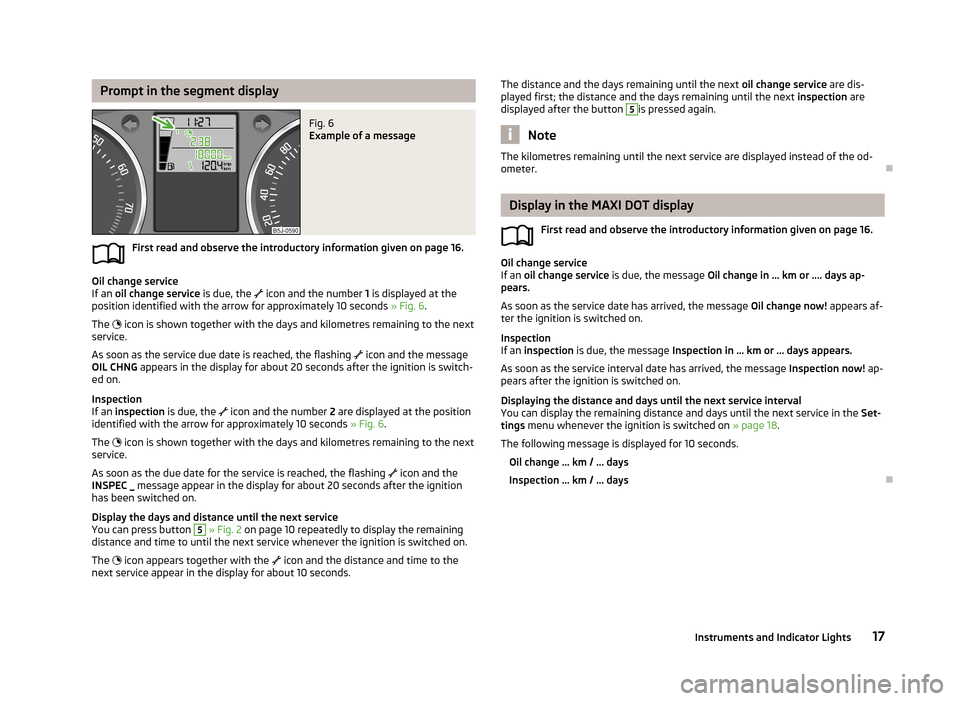
Prompt in the segment displayFig. 6
Example of a message
First read and observe the introductory information given on page 16.
Oil change service
If an oil change service is due, the
icon and the number 1 is displayed at the
position identified with the arrow for approximately 10 seconds » Fig. 6.
The
icon is shown together with the days and kilometres remaining to the next
service.
As soon as the service due date is reached, the flashing
icon and the message
OIL CHNG appears in the display for about 20 seconds after the ignition is switch-
ed on.
Inspection
If an inspection is due, the
icon and the number 2 are displayed at the position
identified with the arrow for approximately 10 seconds » Fig. 6.
The
icon is shown together with the days and kilometres remaining to the next
service.
As soon as the due date for the service is reached, the flashing
icon and the
INSPEC _ message appear in the display for about 20 seconds after the ignition
has been switched on.
Display the days and distance until the next service
You can press button
5
» Fig. 2 on page 10 repeatedly to display the remaining
distance and time to until the next service whenever the ignition is switched on.
The
icon appears together with the
icon and the distance and time to the
next service appear in the display for about 10 seconds.
The distance and the days remaining until the next oil change service are dis-
played first; the distance and the days remaining until the next inspection are
displayed after the button 5
is pressed again.
Note
The kilometres remaining until the next service are displayed instead of the od-
ometer.
Display in the MAXI DOT display
First read and observe the introductory information given on page 16.
Oil change service
If an oil change service is due, the message Oil change in ... km or .... days ap-
pears.
As soon as the service date has arrived, the message Oil change now! appears af-
ter the ignition is switched on.
Inspection
If an inspection is due, the message Inspection in ... km or ... days appears.
As soon as the service interval date has arrived, the message Inspection now! ap-
pears after the ignition is switched on.
Displaying the distance and days until the next service interval You can display the remaining distance and days until the next service in the Set-
tings menu whenever the ignition is switched on » page 18.
The following message is displayed for 10 seconds.
Oil change ... km / ... days
Inspection ... km / ... days
17Instruments and Indicator Lights
Page 22 of 219

Winter tyres
Here, you can set the speed at which an audible signal should sound. This func-
tion is, for example, used for winter tyres where the maximum permissible speed
is lower than the maximum speed of the vehicle.
The following is shown on the information display if this speed is exceeded: Winter tyres: maximum ... km/h.
Units of measurement
The units for the temperature, consumption and distance driven can be set here.
Alt. speed dis.
Display of the second speed in mph 1)
can be activated here.
Service
The days and kilometres remaining until the next service can be displayed here.
Factory setting
The display can be restored to its factory settings here.
Door, boot lid and bonnet warning
First read and observe the introductory information and safety warn-ings
on page 18.
If at least one door is open, or the boot or bonnet is open, the MAXI DOT display
shows the vehicle with the corresponding door or boot/bonnet open.
An audible signal also sounds if the vehicle is travelling at more than 6 km/h.
Auto Check Control
First read and observe the introductory information and safety warn-
ings
on page 18.
Vehicle condition
Certain functions and conditions of individual vehicle systems are checked contin-
uously when the ignition is switched on and also while driving.
Some error messages and other information are displayed in the MAXI DOT dis-
play. The messages are displayed simultaneously with the icons in the MAXI DOT
display or with the warning lights in the instrument cluster » page 20.
The Vehicle status menu item is shown in the main menu of the MAXI DOT dis-
play whenever at least one fault message is present. The first of the fault mes-
sages is displayed after this menu item is selected. Several error messages are
shown on the display under the message e.g. 1/3. This indicates that the first of a
total of three error messages is being displayed.
As long as the operational faults are not rectified, the symbols are always indica- ted again. After they are displayed for the first time, the symbols continue to be
indicated without any extra messages for the driver.
Warning symbolsEngine oil pressure too low» page 21Clutches in the automatic gearbox are too
hot» page 19Check engine oil level,
engine oil sensor defective» page 21
Clutches in the automatic gearbox are too hot
The
symbol in the MAXI DOT display indicates that the temperature of the au-
tomatic gearbox clutches is too high.
The following message is shown in the MAXI DOT display.
Gearbox overheating. Stop. Read manual.
Stop the vehicle, switch off the engine, and wait until the
icon goes out – there
is a risk of gearbox damage. You can continue your journey as soon as the icon
disappears.
WARNINGIf you have to stop for technical reasons, park the vehicle at a safe distance
from the traffic, switch off the engine and switch on the hazard warning lights
system » page 45 . 1)
On models on which the speedometer indicates mph, the second speed is displayed in km/h.
19Instruments and Indicator Lights
Page 28 of 219
ECU fault light (petrol engine)First read and observe the introductory information and safety warn-
ings
on page 20.
If the warning light comes on or begins to flash while driving, a fault exists in
the engine control unit. The engine control unit allows the vehicle to run in emer-
gency mode.
Seek help from a specialist garage.
Diesel particulate filter (diesel engine)
First read and observe the introductory information and safety warn-ings
on page 20.
The diesel particulate filter separates the soot particles from the exhaust. The
soot particles collect in the diesel particulate filter where they are burnt on a reg-
ular basis.
The
warning light comes on if soot has accumulated in the filter.
In order to clean the filter, and where traffic conditions permit »
, the vehicle
should be driven for at least 15 minutes or until the warning light goes out at an
steady speed of at least 60 km/h at engine speeds of 1800 - 2500 rpm with 4th
or 5th gear engaged (automatic gearbox: position S).
The
warning light only goes out once the diesel particulate filter has been
successfully cleaned.
If the filter is not properly cleaned, the warning light
does not go out and the
warning light
begins to flash.
The following message is shown in the MAXI DOT display. Diesel particulate filter: Read manual.
The engine control unit allows the vehicle to run in emergency mode. After switching the ignition off and on again the indicator light, the indicator light
also lights up.
Seek help from a specialist garage.
WARNING■ The diesel particle filter achieves very high temperatures. Therefore do not
park in areas where the hot filter can come into direct contact with dry grass
or other combustible materials – there is the risk of fire.■
Always adjust your speed to suit weather, road, region and traffic condi-
tions. The recommendations indicated by the warning light must not tempt
you to disregard the national regulations for road traffic.
CAUTION
As long as the warning light lights up, one must take into account an in-
creased fuel consumption and in certain circumstances a power reduction of the
engine.
Note
■ We recommend avoiding regularly driving short distances to assist the combus-
tion process of the soot particles in the filter.■
Using diesel fuel with an increased sulphur content can considerably reduce the
service life of the filter. A ŠKODA Service Partner will be able to tell you which countries use diesel fuel with a high sulphur content.
■
If the engine is turned off during the filter cleaning process or shortly after-
wards, the cooling fan may turn on automatically for a few minutes.
Fuel reserve
First read and observe the introductory information and safety warn-ings
on page 20.
The indicator light will come on if the fuel level is less than 7 litres.
An audible signal sounds as a warning signal.
The following message is shown in the MAXI DOT display.
Please refuel. Range: ... km
Note
The text in the MAXI DOT display only goes out after the vehicle has been refuel-
led and driven a short distance.
25Instruments and Indicator Lights
Page 173 of 219
Checking the electrolyte levelFig. 134
Vehicle battery: Electrolyte level
indicator
First read and observe the introductory information and safety warn-
ings on page 168.
We recommend that you have the acid level checked regularly by a specialist ga-
rage, especially in the following cases.
› High outside temperatures.
› Long daily drives
› After each charge
» page 170.
On vehicles with a vehicle battery fitted with a colour indicator, known as the
magic eye » Fig. 134, the electrolyte level can be determined by looking at the
change in colour.
Air bubbles can influence the colour of the indicator. For this reason carefully
knock on the indicator before carrying out the check.
› Black colour - electrolyte level is correct.
› Colourless or light yellow colour - electrolyte level too low, the battery must be
replaced.
Note
■ The battery acid level is also checked regularly by a specialist garage as part of
the inspection service.■
For technical reasons, on vehicles with the description “AGM”, the electrolyte
level cannot be checked.
■
Vehicles with a START-STOP system are fitted with a battery control unit for
checking the energy level for the recurring engine start.
Operation in winter
First read and observe the introductory information and safety warn-
ings
on page 168.
The vehicle battery only has some of its starting power at low temperatures. A
discharged vehicle battery may freeze at temperatures just below 0 °C .
We therefore recommend that you have the battery checked and, if necessary, re-
charged by a specialist garage before the start of the winter.
Charging
First read and observe the introductory information and safety warn-ings
on page 168.
A properly charged vehicle battery is essential for reliably starting the engine.
›
Switch off the ignition and all of the electrical components.
›
Disconnect both battery cables (“negative” first, then “positive”) only when
“rapid charging” the battery.
›
Attach the terminal clamps of the charger to the battery terminals (red = “posi-
tive”, black = “negative”).
›
Plug the mains cable of the charger into the power socket and switch thecharger on.
›
Once charging is complete: Switch off the charger and remove the mains cable
from the power socket.
›
Only then disconnect the charger's terminal clamps.
›
Reconnect the cables to the battery (first “positive”, then “negative”).
It is not necessary to disconnect the battery cables if you are recharging the vehi-
cle battery using low amperages (for example from a mini-charger). Refer to the
charger manufacturer's instructions .
A charging current of 0.1 multiple of the total vehicle battery capacity (or lower)
must be used until full charging is achieved.
Both cables must be disconnected before charging the battery with high amper-
ages, known as “ rapid charging”.
The vent plugs of the vehicle battery should not be opened for charging.
170General Maintenance
Page 175 of 219
Wheels
Tyres and wheel rims
Introduction
This chapter contains information on the following subjects:
Service life of tyres
173
New tyres
174
Unidirectional tyres
175
Tyre pressure monitor
175
Spare wheel
176
Full wheel trim
177
Wheel bolts
177
Hubcaps
177
Wheel bolts
178WARNING■ The national legal regulations must be observed for the use of tyres.■Observe the national legal regulations relating to the use of snow chains
and the maximum vehicle speed with snow chains.WARNINGThe following instructions for the use of tyres must be observed.■For the first 500 km, new tyres do not yet provide optimum grip, and appro-
priate care should therefore be taken when driving – risk of accident!■
Only use radial tyres of the same type, size (rolling circumference) and tread
pattern on all four wheels.
■
For reasons of driving safety, do not replace tyres individually.
■
Never exceed the maximum permissible load bearing capacity for fitted
tyres – risk of accident!
■
Never exceed the maximum permissible speed for fitted tyres – risk of acci-
dent!
WARNING (Continued)■ Incorrect wheel alignment at the front or rear impairs handling – risk of acci-
dent!■
Unusual vibrations or pulling of the vehicle to one side could be a sign of
tyre damage. If there is any doubt that a wheel is damaged, immediately re-
duce your speed and stop! If no external damage is evident, drive slowly and
carefully to the nearest specialist garage to have the vehicle checked.
■
Only use tyres or wheel rims that have been approved by ŠKODA for your
model of vehicle. Failure to observe this instruction may impair the road safety
of your vehicle – risk of accident!
WARNINGObserve the following information regarding tyre damage and wear.■Never use tyres if you do not know anything about the condition and age.■
Never drive with damaged tyres – risk of accident!
■
Immediately replace damaged wheel rims or tyres.
■
You must have your tyres replaced with new ones at the latest when the
wear indicators have been worn down.
■
Worn tyres impair necessary adhesion to the road surface, particularly at
high speeds on wet roads. This could lead to “aquaplaning” (uncontrolled ve- hicle movement – “swimming” on a wet road surface).
WARNINGObserve the following information regarding the tyre inflation pressure.■The tyre control display does not absolve the driver of the responsibility to
ensure the correct tyre inflation pressure. Check the tyre inflation pressure at
regular intervals.■
Insufficient or excessive inflation pressure impairs handling – risk of acci-
dent!
■
If the inflation pressure is too low, the tyre will have to overcome a higher
rolling resistance. This will cause a significant increase in the temperature of
the tyre, especially at higher speeds. This can result in tread separation and a
tyre blowout.
172General Maintenance
Page 176 of 219
WARNINGObserve the following information regarding the wheel bolts.■The wheel bolts must be clean and must turn easily. Never apply grease or
oil.■
The prescribed tightening torque of the wheel bolts for steel and light alloy
wheels is 120 Nm.
■
If the wheel bolts are tightened to an insufficient tightening torque, the
rims may come loose when the car is moving – risk of accident! A tightening
torque which is too high can damage the bolts and threads and this can result
in permanent deformation of the contact surfaces on the rim.
■
If the wheel bolts are handled incorrectly, the wheel may come loose when
the car is moving – risk of accident!
WARNINGObserve the following information regarding the spare wheel.■Only use the spare wheel for as long as is necessary.■
Never drive with more than one spare wheel attached.
■
The snow chains cannot be used on the spare wheel.
CAUTION
■ If a spare wheel is used that is not identical to the fitted tyres, the following
must be observed » page 176, Spare wheel .■
Protect the tyres from contact with oil, grease and fuel.
■
Replace lost valve caps.
■
If, in the event of a puncture, it is necessary to fit a spare wheel with a tyre
without a dedicated running direction or with the opposite direction of rotation, drive carefully as the optimal characteristics of the tyre are no longer applicable in
this situation.
For the sake of the environment
Tyres that are insufficiently inflated increase your fuel consumption.
Note
■ We recommend that any work on the wheels or tyres be carried out by a spe-
cialist garage.■
We recommend that you use wheel rims, tyres, full wheel trims and snow chains
from ŠKODA Original Accessories.
Service life of tyresFig. 135
Principle sketch: Tyre tread with wear indicators/open fuel filler
flap with a table detailing the tyre sizes and tyre inflation pressures
Fig. 136
Replacing wheels
First read and observe the introductory information and safety warn-
ings on page 172.
The service life of tyres depends on the inflation pressure, driving style and other
circumstances. Following the advice below can extend the life cycle of your tyres.
Tyre pressure
Check the tyre pressure, including that of the spare wheel, at least once a month and also before setting off on a long journey.
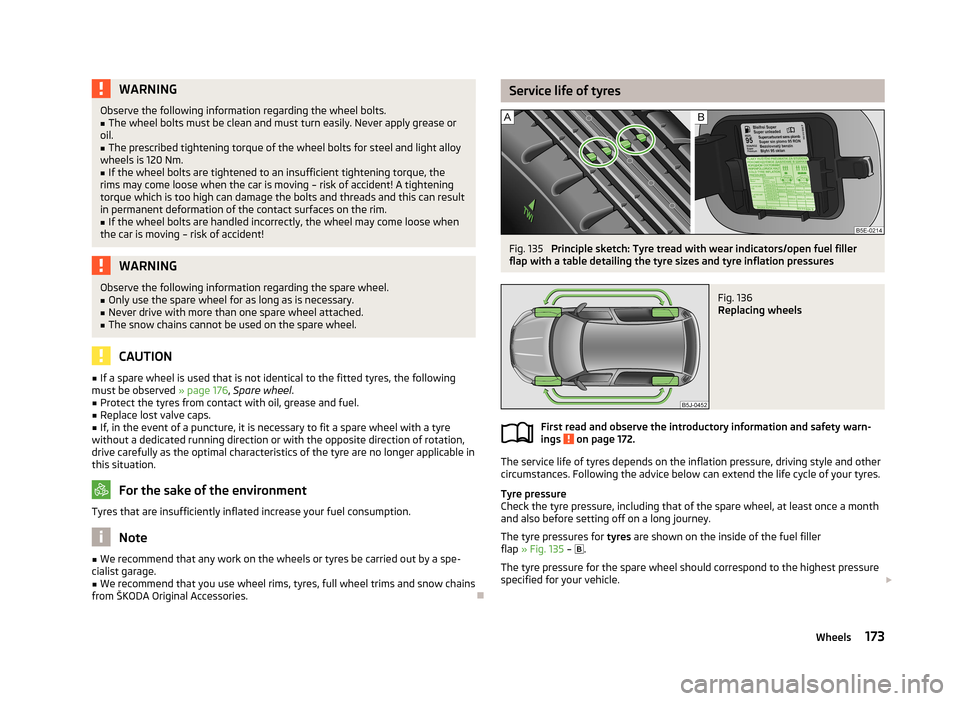
The tyre pressures for tyres are shown on the inside of the fuel filler
flap » Fig. 135 –
.
The tyre pressure for the spare wheel should correspond to the highest pressure
specified for your vehicle.
173Wheels
Page 177 of 219
Always check the inflation pressure when the tyres are cold. Do not reduce the
higher pressure of warm tyres.
With greater additional load, adjust the tyre inflation pressure accordingly.
Driving style
Fast cornering, sharp acceleration and braking increase the wear of your tyres.
Balancing wheels
The wheels of a new vehicle are balanced. When driving, however, there are a
range of factors that may result in an imbalance. This may become apparent by
“vibration” in the steering.
Have the wheels rebalanced after replacing the tyres.
Wheel alignment errors
Incorrect wheel alignment at the front or rear leads to excess wear of the tyres.
Tyre damage
Drive over kerbs and other such obstacles slowly and at right angles wherever
possible in order to avoid damage to tyres and wheel trims.
We recommend checking your tyres and wheel rims for damage (punctures, cuts,
splits and bulges, etc.) on a regular basis. Remove foreign bodies (e.g. small
stones) from the tyre tread immediately.
Replacing wheels
If significantly greater wear is present on the front tyres, we recommend swap-
ping the front wheels with the rear wheels as shown in the diagram » Fig. 136.
You will then obtain approximately the same life for all the tyres.
We recommend that you swap the tyres every 10,000 km in order to achieve evenwear on all tyres and to ensure optimal service life for the tyres.
Storing tyres
Identify disassembled tyres so that the previous direction of rotation can be
maintained if the tyres are reassembled.
Always store wheels or tyres in a cool, dry place that is as dark as possible. Tyres
which are not fixed to a wheel trim should be stored upright.
Wear indicators
The base of the tread of the tyres has 1.6 mm high wear indicators installed.
These wear indicators are arranged evenly spaced around the circumference of the tyre a number of times depending on the make » Fig. 135 -
. Markings on the
walls of the tyres through the letters “TWI”, triangular symbols or other symbols identify the position of the wear indicators.Tyre age
Tyres age and lose their original characteristics, even if they are not being used.
Therefore, we recommend not using summer or winter tyres older than 6 or 4 years old respectively.
New tyres
First read and observe the introductory information and safety warn-
ings
on page 172.
Only use radial tyres of the same type, size (rolling circumference) and tread pat-
tern on one axle on all four wheels.
The tyre/wheel combinations which are approved for your vehicle are indicated in
your vehicle documents.
Where possible, replace tyres by axle. Always fit the tyres with the deeper tread
depth to the front wheels.
Explanation of tyre markings
185/65 R 14 86 T
What this means is:
185Tyre width in mm » Fig. 135 on page 173 - 65Height/width ratio in % » Fig. 135 on page 173 - RCode letter for the tyre construction – Radial » Fig. 135 on page 173
- 14Diameter of wheel in inches » Fig. 135 on page 173 - 86Load index » TSpeed symbol »
The date of manufacture is stated on the tyre wall (possibly on the inside). e.g.
DOT ... 10 13...
means, for example, that the tyre was manufactured in the 10th week of 2013.
Load index
This indicates the maximum permissible load for each individual tyre. 487 kg
515 kg
530 kg
838586174General Maintenance