spare wheel SKODA ROOMSTER 2013 1.G Owner's Manual
[x] Cancel search | Manufacturer: SKODA, Model Year: 2013, Model line: ROOMSTER, Model: SKODA ROOMSTER 2013 1.GPages: 219, PDF Size: 13.83 MB
Page 62 of 219
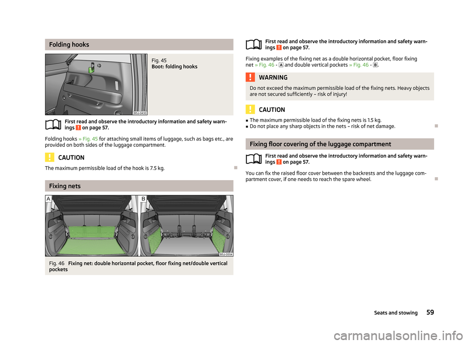
Folding hooksFig. 45
Boot: folding hooks
First read and observe the introductory information and safety warn-
ings on page 57.
Folding hooks » Fig. 45 for attaching small items of luggage, such as bags etc., are
provided on both sides of the luggage compartment.
CAUTION
The maximum permissible load of the hook is 7.5 kg.
Fixing nets
Fig. 46
Fixing net: double horizontal pocket, floor fixing net/double vertical
pockets
First read and observe the introductory information and safety warn-
ings on page 57.
Fixing examples of the fixing net as a double horizontal pocket, floor fixing net » Fig. 46 - and double vertical pockets » Fig. 46 - .
WARNINGDo not exceed the maximum permissible load of the fixing nets. Heavy objects
are not secured sufficiently – risk of injury!
CAUTION
■ The maximum permissible load of the fixing nets is 1.5 kg.■Do not place any sharp objects in the nets – risk of net damage.
Fixing floor covering of the luggage compartment
First read and observe the introductory information and safety warn-
ings
on page 57.
You can fix the raised floor cover between the backrests and the luggage com- partment cover, if one needs to reach the spare wheel.
59Seats and stowing
Page 77 of 219
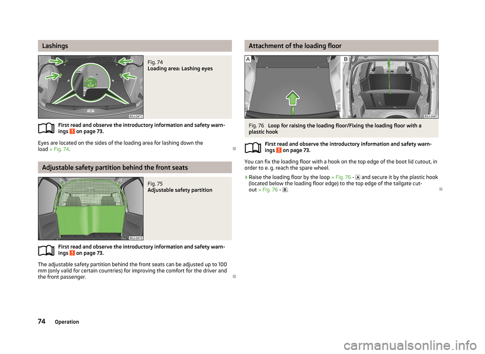
LashingsFig. 74
Loading area: Lashing eyes
First read and observe the introductory information and safety warn-ings on page 73.
Eyes are located on the sides of the loading area for lashing down the
load » Fig. 74 .
Adjustable safety partition behind the front seats
Fig. 75
Adjustable safety partition
First read and observe the introductory information and safety warn-
ings on page 73.
The adjustable safety partition behind the front seats can be adjusted up to 100
mm (only valid for certain countries) for improving the comfort for the driver and
the front passenger.
Attachment of the loading floorFig. 76
Loop for raising the loading floor/Fixing the loading floor with a
plastic hook
First read and observe the introductory information and safety warn-ings
on page 73.
You can fix the loading floor with a hook on the top edge of the boot lid cutout, inorder to e. g. reach the spare wheel.
›
Raise the loading floor by the loop » Fig. 76 -
and secure it by the plastic hook
(located below the loading floor edge) to the top edge of the tailgate cut-
out » Fig. 76 -
.
74Operation
Page 120 of 219
Towing a trailer
Towing device
Introduction
This chapter contains information on the following subjects:
Description
117
Adjusting the ready position
118
Fitting the ball head
118
Check proper fitting
119
Removing the ball head
119
Use and care
120
If your vehicle has already been factory-fitted with towing equipment or is fitted
with towing equipment from ŠKODA Original Accessories, then it meets all of the technical requirements and national legal provisions for towing a trailer.
Your vehicle is fitted with a 13-pin power socket for the electrical connection be-tween the vehicle and trailer. If the trailer that is to be towed has a 7-pin connec-
tor , you can use a suitable adapter from ŠKODA Original Accessories.
The maximum trailer drawbar load is 50 kg/h.
WARNING■
Check that the ball head is seated correctly and is secured in the mounting
recess before starting any journey.■
Do not use the ball head if it is not correctly inserted in the mounting recess.
■
Do not use the towing equipment if it is damaged or incomplete.
■
Do not modify or adapt the towing equipment in any way.
■
Never release the ball head while the trailer is still coupled.
CAUTION
Take care with the ball head to avoid damaging the paintwork on the bumper.
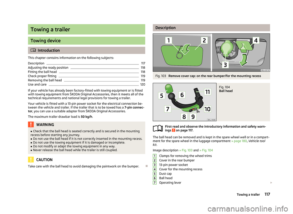
DescriptionFig. 103
Remove cover cap: on the rear bumper/for the mounting recess
Fig. 104
Ball head
First read and observe the introductory information and safety warn-
ings on page 117.
The ball head can be removed and is kept in the spare wheel well or in a compart- ment for the spare wheel in the luggage compartment » page 180, Vehicle tool
kit .
Image description » Fig. 103 and » Fig. 104
Clamps for removing the wheel trims
Cover in the rear bumper
13-pin power socket
Cover for the mounting recess
Dust cap
Ball head
Operating lever
1234567117Towing a trailer
Page 175 of 219
Wheels
Tyres and wheel rims
Introduction
This chapter contains information on the following subjects:
Service life of tyres
173
New tyres
174
Unidirectional tyres
175
Tyre pressure monitor
175
Spare wheel
176
Full wheel trim
177
Wheel bolts
177
Hubcaps
177
Wheel bolts
178WARNING■ The national legal regulations must be observed for the use of tyres.■Observe the national legal regulations relating to the use of snow chains
and the maximum vehicle speed with snow chains.WARNINGThe following instructions for the use of tyres must be observed.■For the first 500 km, new tyres do not yet provide optimum grip, and appro-
priate care should therefore be taken when driving – risk of accident!■
Only use radial tyres of the same type, size (rolling circumference) and tread
pattern on all four wheels.
■
For reasons of driving safety, do not replace tyres individually.
■
Never exceed the maximum permissible load bearing capacity for fitted
tyres – risk of accident!
■
Never exceed the maximum permissible speed for fitted tyres – risk of acci-
dent!
WARNING (Continued)■ Incorrect wheel alignment at the front or rear impairs handling – risk of acci-
dent!■
Unusual vibrations or pulling of the vehicle to one side could be a sign of
tyre damage. If there is any doubt that a wheel is damaged, immediately re-
duce your speed and stop! If no external damage is evident, drive slowly and
carefully to the nearest specialist garage to have the vehicle checked.
■
Only use tyres or wheel rims that have been approved by ŠKODA for your
model of vehicle. Failure to observe this instruction may impair the road safety
of your vehicle – risk of accident!
WARNINGObserve the following information regarding tyre damage and wear.■Never use tyres if you do not know anything about the condition and age.■
Never drive with damaged tyres – risk of accident!
■
Immediately replace damaged wheel rims or tyres.
■
You must have your tyres replaced with new ones at the latest when the
wear indicators have been worn down.
■
Worn tyres impair necessary adhesion to the road surface, particularly at
high speeds on wet roads. This could lead to “aquaplaning” (uncontrolled ve- hicle movement – “swimming” on a wet road surface).
WARNINGObserve the following information regarding the tyre inflation pressure.■The tyre control display does not absolve the driver of the responsibility to
ensure the correct tyre inflation pressure. Check the tyre inflation pressure at
regular intervals.■
Insufficient or excessive inflation pressure impairs handling – risk of acci-
dent!
■
If the inflation pressure is too low, the tyre will have to overcome a higher
rolling resistance. This will cause a significant increase in the temperature of
the tyre, especially at higher speeds. This can result in tread separation and a
tyre blowout.
172General Maintenance
Page 176 of 219
WARNINGObserve the following information regarding the wheel bolts.■The wheel bolts must be clean and must turn easily. Never apply grease or
oil.■
The prescribed tightening torque of the wheel bolts for steel and light alloy
wheels is 120 Nm.
■
If the wheel bolts are tightened to an insufficient tightening torque, the
rims may come loose when the car is moving – risk of accident! A tightening
torque which is too high can damage the bolts and threads and this can result
in permanent deformation of the contact surfaces on the rim.
■
If the wheel bolts are handled incorrectly, the wheel may come loose when
the car is moving – risk of accident!
WARNINGObserve the following information regarding the spare wheel.■Only use the spare wheel for as long as is necessary.■
Never drive with more than one spare wheel attached.
■
The snow chains cannot be used on the spare wheel.
CAUTION
■ If a spare wheel is used that is not identical to the fitted tyres, the following
must be observed » page 176, Spare wheel .■
Protect the tyres from contact with oil, grease and fuel.
■
Replace lost valve caps.
■
If, in the event of a puncture, it is necessary to fit a spare wheel with a tyre
without a dedicated running direction or with the opposite direction of rotation, drive carefully as the optimal characteristics of the tyre are no longer applicable in
this situation.
For the sake of the environment
Tyres that are insufficiently inflated increase your fuel consumption.
Note
■ We recommend that any work on the wheels or tyres be carried out by a spe-
cialist garage.■
We recommend that you use wheel rims, tyres, full wheel trims and snow chains
from ŠKODA Original Accessories.
Service life of tyresFig. 135
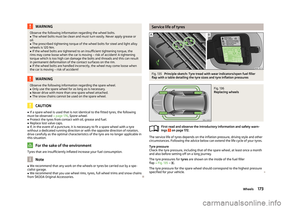
Principle sketch: Tyre tread with wear indicators/open fuel filler
flap with a table detailing the tyre sizes and tyre inflation pressures
Fig. 136
Replacing wheels
First read and observe the introductory information and safety warn-
ings on page 172.
The service life of tyres depends on the inflation pressure, driving style and other
circumstances. Following the advice below can extend the life cycle of your tyres.
Tyre pressure
Check the tyre pressure, including that of the spare wheel, at least once a month and also before setting off on a long journey.
The tyre pressures for tyres are shown on the inside of the fuel filler
flap » Fig. 135 –
.
The tyre pressure for the spare wheel should correspond to the highest pressure
specified for your vehicle.
173Wheels
Page 178 of 219
545 kg
615 kg
630 kg
650 kg
Speed symbol
This indicates the maximum permissible vehicle speed with fitted tyres in each
category.
170 km/h
180 km/h
190 km/h
200 km/h
210 km/h
240 km/h
270 km/h
CAUTION
The information about the load index and the speed symbol is listed in your vehi-
cle documents.
Unidirectional tyres
First read and observe the introductory information and safety warn-
ings
on page 172.
The direction of rotation of the tyres is marked by arrows on the wall of the tyre.
The indicated direction of rotation must be adhered to in order to ensure the op- timal characteristics of these tyres.
These characteristics mainly relate to the following: › Increased driving stability.
› Reduced risk of aquaplaning.
› Reduced tyre noise and tyre wear.
87919293RSTUHVWTyre pressure monitorFig. 137
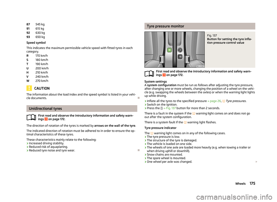
Button for setting the tyre infla-
tion pressure control value
First read and observe the introductory information and safety warn-
ings on page 172.
System settings
A system configuration must be run as follows after adjusting the tyre pressure,
after changing one or more wheels, changing the position of a wheel on the vehi- cle (e.g. swapping the wheels between the axles) or when the warning light lights
up while driving.
›
Inflate all the tyres to the specified pressure » page 26,
Tyre pressures .
›
Switch on the ignition.
›
Press the
» Fig. 137 button for more than 2 seconds.
There is a fault in the system if the
warning light comes on and does not go
out after the system configuration.
There is a system fault if the
warning light flashes.
Tyre pressure indicator
The
warning light comes on in any of the following cases.
› The tyre pressure is low.
› The structure of the tyre is damaged.
› The vehicle is loaded on one side.
› The wheels of one axle are loaded more heavily (e.g. when towing a trailer or
when driving uphill or downhill).
› Snow chains are mounted.
› The spare wheel is mounted.
› One wheel per axle was changed.
175Wheels
Page 179 of 219
WARNING■When the warning light illuminates, immediately reduce the speed and
avoid sudden steering and brake manoeuvres. Stop the vehicle as soon as
possible and inspect the tyres and their inflation pressure.■
Under certain circumstances (e.g. a racy style of driving, wintry or unpaved
roads), the warning light may be delayed or does not light up at all.
CAUTION
■
The tyre control display does therefore not replace the regular tyre inflation
pressure control, as the system cannot detect an even loss of pressure.■
The system cannot warn in case of very rapid loss of tyre pressure, e.g. in the
event of a sudden puncture. In this case carefully bring the vehicle to a standstill without sudden steering movements or sharp braking.
■
The basic setting must be repeated every 10,000 km or once a year to ensure
proper functioning of the tyre pressure monitor.
Spare wheel
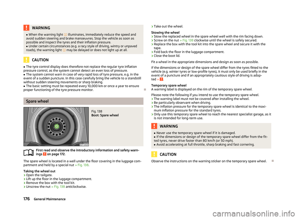
Fig. 138
Boot: Spare wheel
First read and observe the introductory information and safety warn-
ings on page 172.
The spare wheel is located in a well under the floor covering in the luggage com-
partment and held by a special nut » Fig. 138.
Taking the wheel out
›
Open the tailgate.
›
Lift up the floor in the luggage compartment.
›
Remove the box with the tool kit.
›
Unscrew the nut » Fig. 138 anticlockwise.
›Take out the wheel.
Stowing the wheel›
Stow the replaced wheel in the spare wheel well with the rim facing down.
›
Screw on the nut » Fig. 138 clockwise until the wheel is safely secured.
›
Replace the box with the tool kit into the spare wheel and secure it with the
tape.
›
Fold back the floor in the luggage compartment.
›
Close the boot lid.
Fit a wheel in the appropriate dimensions and design as soon as possible.
If the dimensions or design of the spare wheel differ from the tyres fitted to the
vehicle (e.g. winter tyres or low-profile tyres), it must only be used briefly in the
event of a puncture and if an appropriately cautious style of driving is adop-
ted »
.
Temporary spare wheel
A warning label is displayed on the rim of the temporary spare wheel.
Please note the following if you intend to use the temporary spare wheel. › The warning label must not be covered after installing the wheel.
› Be particularly observant when driving.
› The inflation pressure for the temporary spare wheel is identical to the maxi-
mum inflation pressure for the standard tyres.
› Only use this temporary spare wheel to reach the nearest specialist garage, as it
is not intended for long-term use.
WARNING■ Never use the temporary spare wheel if it is damaged.■If the dimensions or design of the temporary spare wheel differ from the fit-
ted tyres, never drive faster than 80 km/h (or 50 mph).■
Avoid accelerating at full throttle, sharp braking and fast cornering.
CAUTION
Observe the instructions on the warning sticker on the temporary spare wheel.
176General Maintenance
Page 180 of 219
Full wheel trimFirst read and observe the introductory information and safety warn-
ings
on page 172.
Pulling off
›
Hook the clamp found in the vehicle tool kit into the reinforced edge of the wheel trim.
›
Push the wheel wrench through the clamp, support on the tyre and pull off the
wheel trim.
Fitting
›
Press the wheel trim onto the wheel rim at the designated valve opening.
›
Then press the trim into the wheel rim until its entire circumference locks cor- rectly in place.
CAUTION
■ Only apply hand pressure, do not hit the full wheel trim! Avoid heavy impacts
when the trim has not yet been inserted into the wheel rim. This could cause
damage to the guide and centring elements of the trim.■
Make sure that the anti-theft wheel bolt is fitted in the bore near the
valve » page 183 , Securing wheels against theft .
■
If wheel trims are retrofitted it must be ensured that an adequate flow of air is
assured to cool the brake system.
Wheel bolts
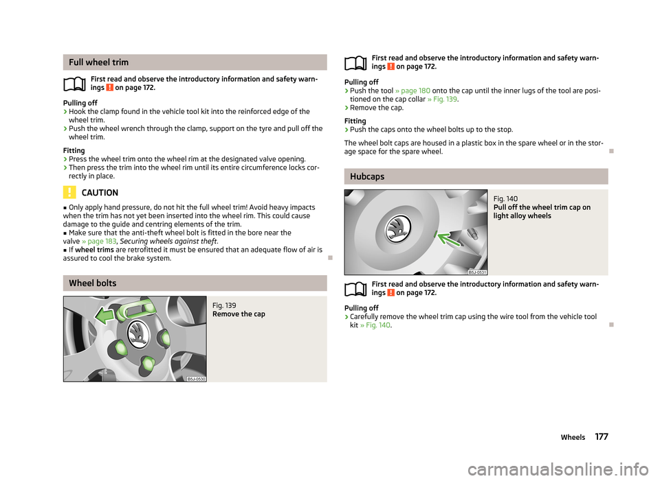
Fig. 139
Remove the capFirst read and observe the introductory information and safety warn-
ings on page 172.
Pulling off
›
Push the tool » page 180 onto the cap until the inner lugs of the tool are posi-
tioned on the cap collar » Fig. 139.
›
Remove the cap.
Fitting
›
Push the caps onto the wheel bolts up to the stop.
The wheel bolt caps are housed in a plastic box in the spare wheel or in the stor-
age space for the spare wheel.
Hubcaps
Fig. 140
Pull off the wheel trim cap on
light alloy wheels
First read and observe the introductory information and safety warn-
ings on page 172.
Pulling off
›
Carefully remove the wheel trim cap using the wire tool from the vehicle tool
kit » Fig. 140 .
177Wheels
Page 183 of 219
Note■The fire extinguisher must comply with national legal requirements.■Pay attention to the expiration date of the fire extinguisher. Proper functioning
of the fire extinguisher is not assured once it has passed its expiry date.■
The fire extinguisher is part of the scope of delivery in certain countries only.
Vehicle tool kit
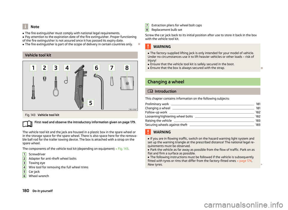
Fig. 143
Vehicle tool kit
First read and observe the introductory information given on page 179.
The vehicle tool kit and the jack are housed in a plastic box in the spare wheel or
in the storage space for the spare wheel. There is also space here for the remova-
ble ball rod for the trailer towing device. The box is attached with a strap on the spare wheel.
The components of the vehicle tool kit (depending on equipment) » Fig. 143.
Screwdriver
Adapter for anti-theft wheel bolts Towing eye
Wire tool for removing the full wheel trims Car jack
Wheel wrench
123456Extraction pliers for wheel bolt caps
Replacement bulb set
Screw the car jack back to its initial position after use to store it back in the box with the vehicle tool kit.WARNING■ The factory-supplied lifting jack is only intended for your model of vehicle.
Under no circumstances use it to lift heavier vehicles or other loads – risk of
injury!■
Ensure that the vehicle tool kit is safely secured in the boot.
■
Ensure that the box is always secured with the strap.
Changing a wheel
Introduction
This chapter contains information on the following subjects:
Preliminary work
181
Changing a wheel
181
Follow-up work
182
Loosening/tightening wheel bolts
182
Raising the vehicle
183
Securing wheels against theft
183WARNING■ If you are in flowing traffic, switch on the hazard warning light system and
set up the warning triangle at the prescribed distance! The national legal re-
quirements must be observed.■
Park the vehicle as far away as possible from the flow of traffic. Park on as
flat and firm a surface as possible.
■
The following instructions must be followed if the vehicle is subsequently
fitted with tyres or rims that differ from the factory-fitted ones » page 174,
New tyres .
78180Do-it-yourself
Page 184 of 219
WARNINGObserve the following instructions for lifting the vehicle.■If the wheel has to be changed on a slope, first of all block the opposite
wheel with a stone or similar object to prevent the vehicle from unexpectedly
rolling away.■
Secure the base plate of the lifting jack with suitable means to prevent pos-
sible moving. A soft and slippery ground under the base plate may move the lifting jack, causing the vehicle to fall down. It is therefore always necessary to
place the lifting jack on a solid surface or use a wide and stable base. Use a non-slip base (e.g. a rubber foot mat) if the surface is smooth, such as cobbled
stones, tiled floor, etc.
■
Only attach the lifting jack to the attachment points provided for this pur-
pose.
■
Always raise the vehicle with the doors closed.
■
Never position any body parts, such as arms or legs under the vehicle, while
the vehicle is raised with a lifting jack.
■
Never start the engine when the vehicle is raised – risk of injury.
CAUTION
■ The tightening torque specified for the wheel bolts for steel and light alloy
wheels is 120 Nm.■
The anti-theft wheel bolt or the adapter can be damaged if the wheel bolts are
tightened too much.
Note
■ The anti-theft wheel bolt set and adapter can be purchased from a ŠKODA Part-
ner.■
The national legal requirements must be observed when changing a wheel.
Preliminary work
First read and observe the introductory information and safety warn-ings
on page 180.
Always change a wheel on a level surface as far as possible.
The following steps must be carried out before actually changing the wheel:
› Have
all the occupants get out. The passengers should not stand on the road
(instead they should remain behind a crash barrier, for instance) while the wheel is being changed.›
Switch off the engine.
›
Move the gearshift lever into Neutral or move the selector lever for the auto-
matic gearbox into position P.
›
Apply the handbrake firmly.
›
Uncouple a trailer.
›
Remove the vehicle tool kit » page 180 and the spare wheel » page 176 , Spare
wheel from the boot.
Changing a wheel
First read and observe the introductory information and safety warn-
ings
on page 180.
›
Remove the full wheel trim » page 177 or caps » page 177 .
›
In the case of light alloy wheel rims remove the wheel trim cap » page 177.
›
First of all slacken the anti-theft wheel bolt and then the other wheel
bolts » page 182 .
›
Jack up the vehicle until the wheel that needs changing is clear of the
ground » page 183 .
›
Unscrew the wheel bolts and place them on a clean surface (cloth, paper, etc.).
›
Remove the wheel carefully.
›
Attach the spare wheel and slightly screw on the wheel bolts.
›
Lower the vehicle.
›
Tighten the opposite wheel bolts alternately (cross-wise) with the wheel
wrench. Tighten the anti-theft wheel bolt last » page 182.
›
Reinstall the wheel trim/wheel trim cap or the caps.
Note
■
All bolts must be clean and must turn easily.■Under no circumstances grease or oil the wheel bolts!■
When fitting unidirectional tyres, ensure that the direction of rotation is cor-
rect » page 172 .
181Emergency equipment and self-help