bulb SKODA ROOMSTER 2014 1.G Owner's Manual
[x] Cancel search | Manufacturer: SKODA, Model Year: 2014, Model line: ROOMSTER, Model: SKODA ROOMSTER 2014 1.GPages: 204, PDF Size: 14.15 MB
Page 6 of 204
Taking care of your vehicle exterior136Taking care of the interior139
Inspecting and replenishing
142
Fuel
142
Engine compartment
145
Engine oil
148
Coolant
150
Brake fluid
152
Vehicle battery
153
Wheels
156
Tyres and wheel rims
156
Approved tyre / rim combinations
160
Winter operation
163
Do-it-yourself
Emergency equipment and self-help
165
Emergency equipment
165
Changing a wheel
166
Puncture set
169
Jump-starting
172
Towing the vehicle
173
Fuses and light bulbs
175
Fuses
175
Replacing bulbs
178
Technical data
Technical data
183
Vehicle data
183
Index
3Table of Contents
Page 42 of 204
The following message is shown in the MAXI DOT display.Gearbox overheated. Stop. Owner's manual!
Stop the vehicle, switch off the engine, and wait until the
icon goes out –
there is a risk of gearbox damage. You can continue your journey as soon as
the icon disappears.WARNINGIf you have to stop for technical reasons, park the vehicle at a safe distance
from the traffic, switch off the engine and switch on the hazard warning
lights system » page 63.
Note
■
Warning messages shown in the MAXI DOT display must be confirmed with
button B » Fig. 25 on page 37 to call up the main menu.■
As long as the operational faults are not rectified, the symbols are always in-
dicated again. After they are displayed for the first time, the symbols continue
to be indicated without any extra messages for the driver.
Warning lights
Introduction
This chapter contains information on the following subjects:
Handbrake
39
Brake system
40
Seat belt warning light
40
Generator
40
Open door
40
Engine oil
40
Coolant
41
Power steering
42
Electronic Stability Control (ESC)
42
Traction Control System (ASR)
42
Anti-lock brake system (ABS)
42
The rear fog light
43
Bulb failure
43
Exhaust inspection system
43
Glow plug system (diesel engine)
43 EPC fault light (petrol engine)43 Diesel particulate filter (diesel engine)43
Fuel reserve
44
Airbag system
44
Tyre pressure
45
Windscreen washer fluid level
45
Traction control (TCS) switched off
45
Turning signal system
46
Low beam
46
Fog lights
46
Cruise control system
46
Selector lever lock
46
Main beam
46
The warning lights show certain functions/faults and may be accompanied by
audible signals.
WARNING■ If illuminated warning lights and the corresponding descriptions and
warning notes are not observed, this may result in severe injuries or major
vehicle damage.■
The engine compartment of your car is a hazardous area. There is a risk of
injuries, scalding, accidents and fire when working in the engine compart-
ment, e.g. inspecting and replenishing oil and other fluids. It is essential to
observe safety notes » page 145, Engine compartment .
Handbrake
Read and observe
on page 39 first.
The warning light comes on if the handbrake is applied. An audible warning
is also given if you drive the vehicle for at least 3 seconds at a speed of more
than 6 km/h.
The following message is shown in the MAXI DOT display. Release parking brake!
39Instruments and Indicator Lights
Page 46 of 204
The following message is shown in the MAXI DOT display.Error: ABS
The vehicle will only be braked by the normal brake system without the ABS.
Seek help from a specialist garage.WARNING■ If you have to stop for technical reasons, then park the vehicle at a safe
distance from the traffic, switch off the engine and activate the hazard
warning light system » page 63.■
If the warning light
» page 40 is displayed simultaneously with the ABS
warning light
,
do not continue your journey! Seek help from a special-
ist garage.
■
A fault to the ABS system or the braking system can increase the vehi-
cle's braking distance – there is a risk of accident.
The rear fog light
Read and observe
on page 39 first.
The warning light comes on when the rear fog lights are operat-
ing » page 62 .
Bulb failure
Read and observe
on page 39 first.
The warning light comes on if a bulb is faulty:
› within a few seconds of the ignition being switched on;
› when a light with a defective bulb is switched on.
The following message may be shown in the MAXI DOT display, for example. INFORMATION Check front right low beam!
Note
The rear side lights and the licence plate lighting have several light bulbs. The
indicator light only lights up if all light bulbs of the licence plate lighting or
the parking light (in one rear light) are defective. For this reason, regular check
that these light bulbs are working correctly. Exhaust inspection system
Read and observe
on page 39 first.
If the warning light
lights up, there is a fault in the exhaust inspection sys-
tem. The engine control unit allows the vehicle to run in emergency mode.
Seek help from a specialist garage.
Glow plug system (diesel engine)
Read and observe
on page 39 first.
The warning light comes on after the ignition has been switched on. The
engine can be started immediately after the pre-glow warning light goes out.
There is a fault in the glow plug system if the warning light
does not come
on at all or lights up continuously .
If the warning light begins to
flash while driving, a fault exists in the engine
control. The engine control unit allows the vehicle to run in emergency mode.
Seek help from a specialist garage.
EPC fault light (petrol engine)
Read and observe
on page 39 first.
If the warning light comes on or begins to flash while driving, a fault exists
in the engine control unit. The engine control unit allows the vehicle to run in
emergency mode.
Seek help from a specialist garage.
Diesel particulate filter (diesel engine)
Read and observe
on page 39 first.
The diesel particulate filter separates the soot particles from the exhaust. The soot particles collect in the diesel particulate filter where they are burnt on a
regular basis.
The warning light comes on if soot has accumulated in the filter.
43Instruments and Indicator Lights
Page 64 of 204
Turn signal and main beam lightsFig. 42
Operating lever: Turn signal and
main beam operation
Read and observe on page 59 first.
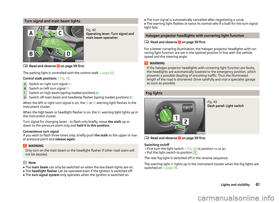
The parking light is controlled with the control stalk » page 63.
Control stalk positions » Fig. 42 .
Switch on right turn signal
Switch on left turn signal
Switch on high beam (spring-loaded position)
Switch off main beam and headlamp flasher (spring-loaded position)
When the left or right turn signal is on, the or
warning light flashes in the
instrument cluster.
When the high beam or headlight flasher is on, the warning light lights up in
the instrument cluster.
Turn signal for changing lanes - to flash only briefly, move the stalk up or
down to the pressure point only and hold it in this position.
Convenience turn signal
If you wish to flash three times only, briefly push the stalk to the upper or low-
er pressure point and release again.
WARNINGOnly turn on the main beam or the headlight flasher if other road users will
not be dazzled.
Note
■ The main beam can only be switched on when the low beam lights are on.■The headlight flasher can be operated even if the ignition is switched off.■
The turn signal system only operates when the ignition is switched on.
ABCD■
The turn signal is automatically cancelled after negotiating a curve.■The warning light flashes at twice its normal rate if a bulb for the turn signal
light fails.
Halogen projector headlights with cornering light function
Read and observe
on page 59 first.
For a better cornering illumination, the halogen projector headlights with cor-nering light function are set in the optimal position in line with the vehicle
speed and the steering angle.
WARNINGIf the halogen projector headlights with cornering light function are faulty,
the headlights are automatically lowered to the emergency position, which
prevents a possible dazzling of oncoming traffic. Thus the illuminated
length of the road is shortened. Drive carefully and visit a specialist garage
as soon as possible.
Fog lights
Fig. 43
Dash panel: Light switch
Read and observe on page 59 first.
Switching on/off
›
First turn the light switch » Fig. 43 to position
or
.
›
Pull the light switch to position
1
.
The rear fog light is switched off in the reverse sequence.
The warning light
lights up in the instrument cluster when the fog lights are
switched on » page 39.
61Lights and visibility
Page 92 of 204
›Undo and remove a bolt
» Fig. 96 - on either side in the upper body and
one bolt » Fig. 96 - in the lower area.›
Move the safety partition into the required position. Ensure it is always move
the same distance- the same number of holes on both sides both upwards
and downwards.
›
On each side in the upper area of the body, undo and remove a bolt and undo
and remove a bolt in the lower area.
›
Have the tightening torque of the bolts checked with a torque wrench as
soon as possible. The tightening torque must be 20 Nm.
›
Change the position of the cover of the luggage compartment floor behind
the safety partition so that it lines up with the new position of the safety
partition.
›
Fold back the loading floor part.
Emergency release of the loading area door
Fig. 97
Emergency unlocking of the
loading area door
Read and observe on page 87 first.
If there is a fault in the central locking, you can unlock the loading area door as
follows:
›
Pull the control cable towards you and pull on it.
›
Press on the loading area door to open it.
›
Press the control cable back again.
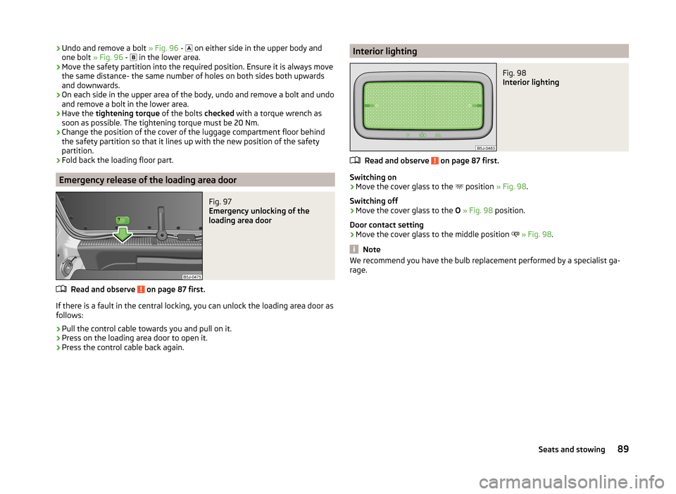
Interior lightingFig. 98
Interior lighting
Read and observe on page 87 first.
Switching on
›
Move the cover glass to the position
» Fig. 98.
Switching off
›
Move the cover glass to the O » Fig. 98 position.
Door contact setting
›
Move the cover glass to the middle position
» Fig. 98 .
Note
We recommend you have the bulb replacement performed by a specialist ga-
rage.89Seats and stowing
Page 137 of 204
any other agreements. You should keep the confirmed warranty certificate and
the receipt for these accessories for this period, so that the commencement of
the warranty term may be verified.
In addition, ŠKODA Service Partners also stock a range of suitable car care
products as well as those parts which are subject to natural wear and tear,
such as tyres, batteries, bulbs and wiper blades.
Note
The accessories authorized by ŠKODA AUTO a.s. will be offered by the ŠKODA
Partners in all countries where ŠKODA AUTO a.s. has a sales and service net- work. This will usually be in the form of a printed catalogue of Original ŠKODA
Accessories, in the form of separate printed brochures or in the form of offers
for ŠKODA Genuine Accessories on the ŠKODA Partner's website.
Spoiler
Read and observe
on page 132 first.
If your new vehicle is fitted with a spoiler on the front bumper in combination
with the spoiler on the luggage compartment lid, then the following instruc-
tions must be adhered to.
› For safety reasons, the vehicle must only be fitted with a spoiler on the front
bumper in combination with the associated spoiler on the luggage compart-
ment lid.
› This kind of spoiler cannot be left on the front bumper either on its own, in
combination with another spoiler not on the luggage compartment lid or in
combination with an unsuitable spoiler on the luggage compartment lid.
› We recommend that you consult the ŠKODA service partner for any repairs to
or replacement, addition or removal of spoilers.
WARNING■ If work on your vehicle's spoilers is not carried out properly, this can lead
to operational faults - risk of accident and serious injuries.■
If a front spoiler, full wheel trim, etc. is mounted retrospectively, it must
be ensured that the air supply to the front wheel brakes is not reduced.
The front brakes may overheat, which can have a negative impact on the
functioning of the braking system – there is a risk of an accident!
Airbags
Read and observe
on page 132 first.
The system components of the airbag system can be situated in the front
bumper, doors, front seats, roof lining or body.
WARNINGAny work on the airbag system including the installation and removal of
system components due to other repair work (e.g. removal of the steering
wheel) must only be carried out by a specialist garage.■
Modifications, repairs and technical alterations that have been carried out
unprofessionally can cause damage and operational faults, and can also se-
riously impair the effectiveness of the airbag system – risk of accident and
fatal injury!
■
The airbag system will then have to be replaced if the airbag is deployed.
Airbag modules cannot be repaired.
WARNINGInformation on the use of the airbag system■It is prohibited to manipulate individual parts of the airbag system, as this
might result in the airbag being deployed.■
Never install any airbag parts into the vehicle that have been removed
from old cars or have been recycled.
■
Never install damaged airbag parts in the vehicle. The airbags may then
not be deployed properly or even at all in the event of an accident.
■
No modifications of any kind must be made to parts of the airbag system.
WARNING■ A change to the vehicle's wheel suspension, including the use of non-ap-
proved wheels and tire combinations, can alter the functioning of the air-
bag system - risk of accident and fatal injury!■
Never make any changes to the front bumper or the bodywork.
134General Maintenance
Page 169 of 204
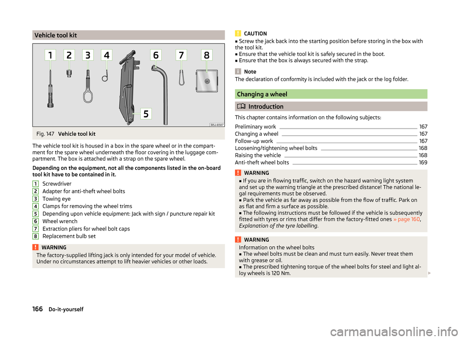
Vehicle tool kitFig. 147
Vehicle tool kit
The vehicle tool kit is housed in a box in the spare wheel or in the compart-
ment for the spare wheel underneath the floor covering in the luggage com-
partment. The box is attached with a strap on the spare wheel.
Depending on the equipment, not all the components listed in the on-board
tool kit have to be contained in it.
Screwdriver
Adapter for anti-theft wheel bolts
Towing eye
Clamps for removing the wheel trims
Depending upon vehicle equipment: Jack with sign / puncture repair kit
Wheel wrench
Extraction pliers for wheel bolt caps
Replacement bulb set
WARNINGThe factory-supplied lifting jack is only intended for your model of vehicle.
Under no circumstances attempt to lift heavier vehicles or other loads.12345678CAUTION■ Screw the jack back into the starting position before storing in the box with
the tool kit.■
Ensure that the vehicle tool kit is safely secured in the boot.
■
Ensure that the box is always secured with the strap.
Note
The declaration of conformity is included with the jack or the log folder.
Changing a wheel
Introduction
This chapter contains information on the following subjects:
Preliminary work
167
Changing a wheel
167
Follow-up work
167
Loosening/tightening wheel bolts
168
Raising the vehicle
168
Anti-theft wheel bolts
169WARNING■ If you are in flowing traffic, switch on the hazard warning light system
and set up the warning triangle at the prescribed distance! The national le-
gal requirements must be observed.■
Park the vehicle as far away as possible from the flow of traffic. Park on
as flat and firm a surface as possible.
■
The following instructions must be followed if the vehicle is subsequently
fitted with tyres or rims that differ from the factory-fitted ones » page 160,
Explanation of the tyre labelling .
WARNINGInformation on the wheel bolts■The wheel bolts must be clean and must turn easily. Never treat them
with grease or oil.■
The prescribed tightening torque of the wheel bolts for steel and light al-
loy wheels is 120 Nm.
166Do-it-yourself
Page 178 of 204
NoteThe detachable ball rod must always be in the vehicle so that it can be used for
towing, if necessary.Fuses and light bulbs
Fuses
Introduction
This chapter contains information on the following subjects:
Fuses in the dash panel
176
Fuses in the engine compartment
177
Individual electrical circuits are protected by fuses.
› Before replacing a fuse, switch off the ignition and the appropriate consumer
› Find out which fuse belongs to the component that is not operat-
ing » page 176 , Fuses in the dash panel or » page 177 , Fuses in the engine
compartment .
› Take the plastic clip out of its fixture in the cover of the fuse box, place it on
the relevant fuse and pull it out.
Fuse colourMaximum amperagelight brown5dark brown7.5red10blue15yellow20white25green30WARNINGAlways read and observe the warnings before completing any work in the
engine compartment » page 145.
CAUTION
■
“Never repair” fuses or replace them with a fuse of a higher amperage –
there is a risk of fire. This may also cause damage at another part of the elec-
trical system.■
A blown fuses is recognisable by the molten metal strip. Replace the faulty
fuse with a new one of the same amperage.
■
If a newly inserted fuse burns through again, then a specialist should be con-
sulted immediately.
175Fuses and light bulbs
Page 180 of 204
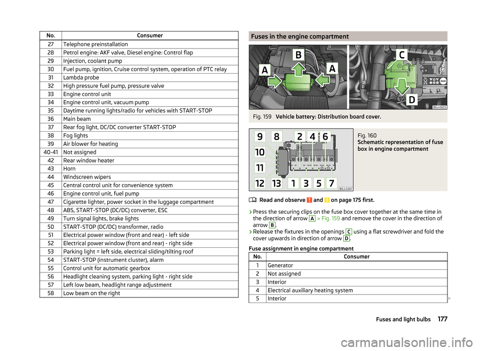
No.Consumer27Telephone preinstallation28Petrol engine: AKF valve, Diesel engine: Control flap29Injection, coolant pump30Fuel pump, ignition, Cruise control system, operation of PTC relay31Lambda probe32High pressure fuel pump, pressure valve33Engine control unit34Engine control unit, vacuum pump35Daytime running lights/radio for vehicles with START-STOP36Main beam37Rear fog light, DC/DC converter START-STOP38Fog lights39Air blower for heating40-41Not assigned42Rear window heater43Horn44Windscreen wipers45Central control unit for convenience system46Engine control unit, fuel pump47Cigarette lighter, power socket in the luggage compartment48ABS, START-STOP (DC/DC) converter, ESC49Turn signal lights, brake lights50START-STOP (DC/DC) transformer, radio51Electrical power window (front and rear) - left side52Electrical power window (front and rear) - right side53Parking light = left side, electrical sliding/tilting roof54START-STOP (instrument cluster), alarm55Control unit for automatic gearbox56Headlight cleaning system, parking light - right side57Left low beam, headlight range adjustment58Low beam on the rightFuses in the engine compartmentFig. 159
Vehicle battery: Distribution board cover.
Fig. 160
Schematic representation of fuse
box in engine compartment
Read and observe and on page 175 first.
› Press the securing clips on the fuse box cover together at the same time in
the direction of arrow
A
» Fig. 159 and remove the cover in the direction of
arrow
B
.
› Release the fixtures in the openings
C
using a flat screwdriver and fold the
cover upwards in direction of arrow
D
.
Fuse assignment in engine compartment
No.Consumer1Generator2Not assigned3Interior4Electrical auxiliary heating system5Interior 177Fuses and light bulbs
Page 181 of 204
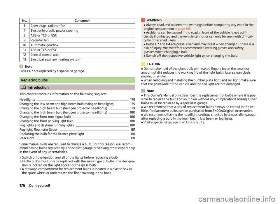
No.Consumer6Glow plugs, radiator fan7Electro-hydraulic power steering8ABS or TCS or ESC9Radiator fan10Automatic gearbox11ABS or TCS or ESC12Central control unit13Electrical auxiliary heating system
Note
Fuses 1-7 are replaced by a specialist garage.
Replacing bulbs
Introduction
This chapter contains information on the following subjects:
Headlights
179
Changing the low beam and high beam bulb (halogen headlights)
179
Changing the high beam bulb (halogen projector headlights)
179
Changing the high beam bulb (halogen projector headlights)
180
Changing the front turn signal bulb
180
Changing the front parking light bulb
180
Fog lights and daytime running lights
180
Fog light, Roomster Scout
181
Replacing the bulb for the licence plate light
181
Rear Light
181
Some manual skills are required to change a bulb. For this reason, we recom-
mend having bulbs replaced by a specialist garage or seeking other expert help
in the event of any uncertainties.
› Switch off the ignition and all of the lights before replacing a bulb.
› Faulty bulbs must only be replaced with the same type of bulbs. The designa-
tion is located on the light socket or the glass bulb.
› A stowage compartment for replacement bulbs is located in a plastic box in
the spare wheel or underneath the floor covering in the boot.
WARNING■ Always read and observe the warnings before completing any work in the
engine compartment » page 145.■
Accidents can be caused if the road in front of the vehicle is not suffi-
ciently illuminated and the vehicle cannot or can only be seen with difficul-
ty by other road users.
■
Bulbs H7 and H4 are pressurised and may burst when changed - there is a
risk of injury. We therefore recommended wearing gloves and safety
glasses when changing a bulb.
■
Switch off the respective vehicle light when changing the bulb.
CAUTION
■ Do not take hold of the glass bulb with naked fingers (even the smallest
amount of dirt reduces the working life of the light bulb). Use a clean cloth,
napkin, or similar.■
When removing and installing the number plate light and tail light make sure
that the paintwork of the vehicle and the tail light are not damaged.
Note
■ This Owner's Manual only describes the replacement of bulbs where it is pos-
sible to replace the bulbs on your own without any complications arising. Other
bulbs must be replaced by a specialist garage.■
We recommend that a box of replacement bulbs always be carried in the ve-
hicle. Replacement bulbs can be purchased from ŠKODAOriginal Accessories.
■
We recommend having the headlight settings checked by a specialist garage
after replacing a bulb in the main beam, low beam or fog lights.
■
Visit a specialist garage if an LED is faulty.
178Do-it-yourself