load capacity SKODA ROOMSTER 2014 1.G Owner's Manual
[x] Cancel search | Manufacturer: SKODA, Model Year: 2014, Model line: ROOMSTER, Model: SKODA ROOMSTER 2014 1.GPages: 204, PDF Size: 14.15 MB
Page 34 of 204
Button for:› Reset trip meter
» page 32
› Set hours/minutes
› Enable/disable the mode selected by means of button 5
Fuel gauge 1)
» page 31
Engine revolutions counter
Read and observe
on page 30 first.
The red scale range of the rev counter
1
» Fig. 20 on page 30 indicates the
range in which the engine control unit begins to limit the engine speed. The
engine control unit restricts the engine speed to a steady limit.
You should shift into the next higher gear before the red scale of the revolu-
tion counter is reached, or move the selector lever into position D if your car is
fitted with an automatic gearbox.
To maintain the optimum motor speed, observe the gearshift indica-
tor » page 32 .
For the sake of the environment
Shifting up in good time has the following benefits.■It helps to reduce fuel consumption.■
It reduces engine noise.
■
It protects the environment.
■
It benefits the life and reliability of the engine.
Speedometer
Read and observe
on page 30 first.
Warning against speeding
An audible warning will sound when the vehicle speed exceeds 120 km/h 2)
. The
audible warning is switched off once the vehicle speed falls below 120 km/h.
67Coolant temperature gauge display
Read and observe
on page 30 first.
The coolant temperature gauge
4
» Fig. 20 on page 30 works only when the
ignition is switched on.
In vehicles with a segment display, the coolant temperature is indicated only
by one of the warning lights » page 41,
Coolant coming on or going off.
Cold range
The pointer in the left of the scale indicates that the engine has not yet
reached its operating temperature. Avoid high speeds, full throttle and high engine loads. This prevents possible damage to the engine.
The operating range
The engine has reached its operating temperature as soon as the pointer
moves into the middle of the scale. At very high ambient temperatures or un-
der heavy engine loads, the pointer may move even further to the right.
High temperature range
The coolant temperature is too high if the pointer reaches the red area of the
scale. Further information » page 41.
CAUTION
■
Additional headlights and other attached components in front of the air inlet
impair the cooling efficiency of the coolant.■
Never cover the radiator - there is a risk of the engine overheating.
Fuel gauge
Read and observe
on page 30 first.
The fuel gauge
7
» Fig. 20 on page 30 only works when the ignition is switch-
ed on.
The fuel remaining is displayed in the segment display on vehicles with the
segment display.
The fuel tank has a capacity of about 55 litres. The warning light lights up
when the fuel level reaches the reserve range
» page 44 .
1)
Applies for vehicles using the MAXI DOT display.
2)
This function is only enabled in certain countries.
31Instruments and Indicator Lights
Page 73 of 204
›Switch the front seat heating to 25 % or 100 % power by pressing rocker
switch at position 1 or 2 » Fig. 55 .›
To switch off the heating shift the rocker switch into the horizontal position.
WARNINGIf, as an occupant, you have a subdued pain and/or temperature sensitivity,
e.g. through medication, paralysis or because of chronic illness (e.g. diabe-
tes), we recommend not to use the seat heating. This can lead to burns on
the back, the posterior and the legs which are difficult to heal. If the seat
heating is used, we recommend to make regular breaks in your journey
when driving long distances, so that the body can recuperate from the
stress of the journey. Please consult your doctor, who can evaluate your
specific condition.
CAUTION
■ Do not kneel on the seats or otherwise apply pressure at specific points to
avoid damaging the heating elements for the seat heaters.■
Do not turn on the seat heater if seats are not occupied.
■
Do not switch on the seat heating if the seats have objects attached to or
placed on them, for example a child seat, a bag, etc. A fault of the heating ele-
ments in the seat heating can occur.
■
If additional seat covers or protective covers are attached to the seats, do
not turn on the seat heater - there is a risk of damaging the seat covers and
seat heating.
■
Do not clean the seats using moisture » page 141, Seat covers .
Note
■
The seat heating should only be switched on when the engine is running.
This has a significant effect of saving on the battery capacity.■
If the on-board voltage drops, the seat heating is switched off automatically,
in order to provide sufficient electrical energy for the engine con-
trol » page 156 , Automatic load deactivation .
Rear seats
Introduction
This chapter contains information on the following subjects:
Setting theSetting the seats in the longitudinal direction
70
Setting theinclination of the seat backrest
70
Fold downseat backrest and seat fold down completely
71Unlocking and removing seats71Adjusting seats in crosswise direction72
Folding the rear seats into the starting position
72
Setting theSetting the seats in the longitudinal direction
Fig. 56
Adjusting seats in forward/back
direction
›
Pull lever
A
in the direction of arrow
1
and move the seat to the desired po-
sition in the direction of arrow
2
» Fig. 56 .
Setting theinclination of the seat backrest
Fig. 57
Adjusting the seat backrest
›
Pull the lever
1
» Fig. 57 and adjust the required inclination of the seat
backrest.
WARNINGCheck for yourself that the seat backrest is engaged by pulling on it.70Operation
Page 83 of 204
›Pull the belt through the tensioning clasps on both sides in turn.›If necessary, you can correct the position of the bicycles in the vehicle.
Roof rack system
Introduction
This chapter contains information on the following subjects:
Roof load
80WARNING■ The transported items on the roof rack must be securely attached – risk
of accident!■
Always secure the load with appropriate and undamaged lashing straps
or tensioning straps.
■
Distribute the load evenly over the roof rack system.
■
Transporting heavy or large objects on the roof rack alters the handling
properties of the vehicle due to the displacement of the centre of gravity or
the increased wind exposure area – risk of accident! The style of driving
and speed must therefore be adapted to the current circumstances.
■
Avoid abrupt and sudden driving/braking manoeuvres.
■
Adjust the speed and driving style to the visibility, weather, road and traf-
fic conditions.
■
The permissible roof load, permissible axle loads and permissible total ve-
hicle weight must not be exceeded under any circumstances – risk of acci-
dent!
CAUTION
■ Only roof racks from the ŠKODA Original Accessories range should be used.■The fitting instructions supplied with the roof luggage rack system must be
observed when handling roof racks.■
Ensure that the boot lid does not hit the roof load when opened.
■
The height of the vehicle changes after mounting a roof luggage rack system
and the load that is secured to it. Compare the vehicle height with available
clearances, such as underpasses and garage doors.
■
Always remove the roof luggage rack system before entering an automated
car wash.
■
Ensure the roof aerial is not impaired by the secured load.
For the sake of the environment
The increased aerodynamic drag results in a higher fuel consumption.NoteIf the vehicle is not factory-equipped with a roof rack, it can be purchased from
the ŠKODA Original Accessories.
Roof load
Read and observe
and on page 80 first.
The maximum permissible roof load (including roof rack system) of 75 kg and
the maximum permissible total weight of the vehicle should not be exceeded.
The full permissible roof load cannot be used if a roof rack system with a lower
load carrying capacity is used. In this case, the roof rack system must only be
loaded up to the maximum weight limit specified in the fitting instructions.
Useful equipment
Introduction
This chapter contains information on the following subjects:
Cupholders
81
Ashtray
81
Cigarette lighter
82
12-volt power outlet
82
Clothes hook
83
Car park ticket holder
83WARNING■ Do not place anything on the dash panel. These objects might slide or fall
down while you are driving (under acceleration or when cornering) and
could distract you from the traffic - there is a risk of an accident.■
Make sure that no objects from the centre console or from other storage
compartments can get into the driver's footwell while you are driving. You
would not be able to brake, operate the clutch pedal or accelerate - danger
of causing an accident!
■
Ash and cigarette or cigar stubs must only be discarded in ashtrays.
80Operation
Page 153 of 204
We recommend maintaining the oil level within the range A, but not above , if
the engine has been operating at high loads, for example, during a lengthy
motorway trip during the summer months, towing a trailer or negotiating a
high mountain pass.
The warning light in the instrument cluster will indicate whether the oil level is
too low » page 40 ,
Engine oil . Check the oil level using the dipstick as
soon as possible. Add oil accordingly.
CAUTION
The oil level must never be above the A range » Fig. 136 – there is a risk of
damaging the exhaust system!
Replenishing
Read and observe
and on page 148 first.
›
Check the oil level » page 149.
›
Unscrew the cap of the engine oil filler opening » Fig. 134 on page 147 .
›
Replenish the oil in portions of 0.5 litres in accordance with the correct speci-
fications » page 148 , Specifications and capacity .
›
Check the oil level » page 149.
›
Carefully screw on the oil filler opening cap and push the dipstick in fully.
Coolant
Introduction
This chapter contains information on the following subjects:
Capacity
151
Checking the coolant level
151
Replenishing
151
The coolant consists of water with coolant additive. This mixture guarantees
antifreeze protection, protects the cooling/heater system against corrosion
and prevents lime formation.
Vehicles exported to countries with a mild climate are already factory-filled
with a coolant which offers antifreeze protection down to about -25 ℃. In
these countries, the concentration of coolant additive should be at least 40%.
Vehicles exported to countries with a cold climate are already factory-filled
with a coolant which offers antifreeze protection down to about -35 °C. In
these countries, the concentration of coolant additive should be at least 50%.
If a higher concentration of antifreeze is required for climatic reasons, the con-
centration of coolant additive can be increased up to a maximum of 60% (anti-
freeze protection down to approx. -40 °C).
When refilling, only use the same antifreeze identified on the coolant expan-
sion vessel » Fig. 137 on page 151 .WARNINGThe engine compartment of your car is a hazardous area. The following
warning instructions must be followed at all times when working in the en- gine compartment » page 145.
CAUTION
■
Do not continue your journey if for some reason it is not possible to top up
the coolant under the prevailing conditions! Switch off the engine and seek as-
sistance from a specialist garage.■
If the expansion tank is empty, do not top up with coolant. The system could
ventilate - there is a risk of engine damage,
do not continue driving! Switch
off the engine and seek assistance from a specialist garage.
■
The concentration of coolant additive in the coolant must never be under
40%.
■
Over 60% of coolant additive in the coolant reduces the antifreeze protec-
tion and cooling effect.
■
A coolant additive that does not comply with the correct specifications can
significantly reduce the corrosion protection.
■
Any faults resulting from corrosion may cause a loss of coolant and can con-
sequently result in major engine damage!
■
Do not fill the coolant above the mark
A
» Fig. 137 on page 151 .
■
If a fault causes the engine to overheat, we recommend visiting a specialist
garage, as otherwise serious engine damage may occur.
■
Additional headlights and other attached components in front of the air inlet
impair the cooling efficiency of the coolant.
■
Never cover the radiator - there is a risk of the engine overheating.
150General Maintenance
Page 159 of 204
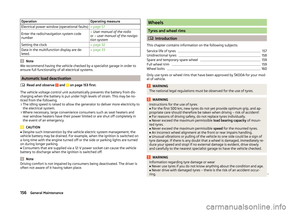
OperationOperating measureElectrical power window (operational faults)» page 57Enter the radio/navigation system code
number» User manual of the radio
or » user manual of the naviga-
tion systemSetting the clock» page 32Data in the multifunction display are de-
leted.» page 33
Note
We recommend having the vehicle checked by a specialist garage in order to
ensure full functionality of all electrical systems.
Automatic load deactivation
Read and observe
and on page 153 first.
The vehicle voltage control unit automatically prevents the battery from dis-
charging when the battery is put under high levels of strain. This may be no-
ticed from the following.
› The idling speed is raised to allow the generator to deliver more electricity to
the electrical system.
› Where necessary, large convenience consumers such as seat heaters and
rear window heaters have their power limited or are shut off completely in
the event of an emergency.
CAUTION
■ Despite such intervention by the vehicle electric system management, the
vehicle battery may be drained. For example, when the ignition is switched on
a long time with the engine turned off or the side or parking lights are turned
on during longer parking.■
Consumers that are supplied via a 12-V power socket can cause the vehicle
battery to discharge when the ignition is switched off.
Note
Driving comfort is not impaired by consumers being deactivated. The driver is
often not aware of it having taken place.Wheels
Tyres and wheel rims
Introduction
This chapter contains information on the following subjects:
Service life of tyres
157
Unidirectional tyres
158
Spare and temporary spare wheel
159
Full wheel trim
159
Wheel bolts
160
Only use tyres or wheel rims that have been approved by ŠKODA for your mod-
el of vehicle.
WARNINGThe national legal regulations must be observed for the use of tyres.WARNINGInstructions for the use of tyres■For the first 500 km, new tyres do not yet provide optimum grip, and ap-
propriate care should therefore be taken when driving – risk of accident!■
For reasons of driving safety, do not replace tyres individually.
■
Never exceed the maximum permissible load bearing capacity of moun-
ted tyres.
■
Never exceed the maximum permissible speed for the mounted tyres.
■
An incorrect wheel alignment at the front or rear impairs handling.
■
Unusual vibrations or pulling of the vehicle to one side could be a sign of
tyre damage. If there is any doubt that a wheel is damaged, immediately re-
duce your speed and stop! If no external damage is evident, drive slowly
and carefully to the nearest specialist garage to have the vehicle checked.
WARNINGInformation regarding tyre damage or wear■Never use tyres if you do not know anything about the condition and age.■
Never drive with damaged tyres – there is the risk of an accident occur-
ring.
156General Maintenance
Page 187 of 204
Operating weight and payload
Operating weight
This value represents the minimum operating weight without additional
weight-increasing equipment such as air conditioning system, spare wheel, or
trailer hitch.
The specified operating weight is for orientation purposes only.
The operating weight also contains the weight of the driver (75 kg), the weight
of the operating fluids, the tool kit, and a fuel tank filled to 90 % capacity.
Operating weight of the vehicle » page 186, Vehicle-specific details per en-
gine type .
Payload
It is possible to calculate the approximate maximum payload from the differ-
ence between the permissible total weight and the operating weight.
The payload consists of the following weights.
› The weight of the passengers.
› The weight of all items of luggage and other loads.
› The weight of the roof, including the roof rack system.
› The weight of the equipment that is excluded from the operating weight.
› Trailer drawbar load when towing a trailer (max. 50 kg).
Note
If required, you can find out the precise weight of your vehicle at a specialist
garage.
Measurement of fuel consumption and CO 2 emissions according to
ECE Regulations and EU Directives
The data on fuel consumption and CO 2 emissions were not available at the
time of going to press.
The data on fuel consumption and CO 2 emissions are given on the ŠKODA
websites or in the sales and technical vehicle documentation.
The measurement of the intra-urban cycle begins with a cold start of the en-
gine. Afterwards urban driving is simulated.
In the extra-urban driving cycle, the vehicle is accelerated and decelerated in
all gears, corresponding to daily routine driving conditions. The driving speed
varies between 0 and 120 km/h.
The calculation of the combined fuel consumption considers a weighting of
about 37 % for the intra-urban cycle and 63 % for the extra-urban cycle.
Note
■ The fuel consumption and emission levels given on the ŠKODA websites or in
the commercial and technical vehicle documentation have been established in
accordance with rules and under conditions that are set out by legal or techni-
cal rules for the determination of operational and technical data of motor vehi-
cles.■
Depending on the extent of the equipment, the driving style, traffic condi-
tions, weather influences and vehicle condition, consumption values can in
practice result in fuel economy figures in the use of the vehicle that differ from
the fuel consumption values listed on the ŠKODA websites or in the commer-
cial and technical vehicle documentation.
184Technical data
Page 195 of 204
DoorChild safety lock48
Closing48
Indicator light for an open door40
Opening48
Doors Emergency locking
49
Driving Abroad
118
Driving through water on streets117
Emissions184
Fuel consumption184
Maximum speed186
Driving economically Economical gear changing
114
Driving through water117
E
Economical and environmentally friendly driv- ing
113
Economical driving Ballast
115
Driving at full throttle115
Idling115
Looking ahead114
Regular maintenance116
Saving energy116
Short distances115
Tyre pressure115
EDL120
Electrical power windows Button in the driver's door
55, 56
Button in the rear door56
Central locking system57
Operational faults57
Electronic Differential Lock120
Electronic immobilizer107
emergency opening the loading door (Praktik)
89
EmergencyChanging a wheel166
Hazard warning light system63
jump-starting172
Jump-starting172
locking of the doors49
Selector lever-unlocking112
Towing the vehicle173
Towing the vehicle using the tow hitch174
tyre repair169
Unlocking the boot lid55
Emergency equipment Fire extinguisher
165
First aid kit165
Jack166
Vehicle tool kit166
Warning triangle165
Emissions184
Engine Running in
113
Starting and stopping the engine106
Switching off the engine107
Engine compartment145
Brake fluid152
Coolant151
Overview147
Vehicle battery153
Engine number183
Engine oil148
Capacity148
Checking149
Replenishing150
Specifications148
Warning light40
Engine revolutions counter31
Environment113
Environmental compatibility116
Environmentally friendly driving113
ESC Function119
Warning light42
F
Films
137
Fire extinguisher165
First aid kit165
Flashers61
Fog lights61
Folding down the seats
70
Footmats109
see Footmats109
Front airbag18
Front seats69
Fuel142
Diesel144
Fuel gauge31
gauge31
refer to Fuel142
Refuelling143
Unleaded petrol143
Fuel consumption113, 184
Fuses Assignment
175
Colour coding175
Replacing175
G
Gear Recommended gear
32
Gearbox Display messages
38
Gear changing Gear stick
109
General view Cockpit
29
Genuine parts133
192Index
Page 199 of 204
Washing by hand135
Wash system135
Wax treatment137
Taking care of your vehicles Fabric covers
141
Technical data183
Telephone97
Temporary spare wheel159
the rear seats fold down seat backrest and fold seat fully for-ward
71
Tiptronic111
Tire size see wheels
161
Tools166
TOP TETHER26
Tourist lights62
Towing173
Towing a trailer131
Towing device Description
126
Use and care139
Towing eye Front
174
Rear174
Towing protection54
Traction Control System (ASR)120
Trailer129
13-pin socket130
connection and disconnection130
Loading130
Safety eye130
Towing a trailer131
Trailer operation126
Transport Boot
73
Roof rack system80
Transporting children safely22
Trays folding table in the middle back seat86
Turning the light on and off
59
Turning the light on and off59
Turn signals61
Two-way radio systems97
Tyre Explanation of the labelling
160
see wheels160
Tyre load-bearing capacity Refer to Wheels
161
Tyre pressure Indicator light
45
Tyre pressure monitoring125
Display45
Save tyre pressure values125
Tyre repair Preparations
171
Pressure test171
Sealing and inflating the tyre171
Tyres156
Inflation pressure157
Sizes157
Tyre wear indicator157
Tyre size160, 161
see wheels160
U
Underbody protection
139
Unleaded petrol118
unlock Central locking system
51
Unlocking Remote control
52
without central locking49
Unlocking and locking47
USB104
Useful equipment80
12-volt power outlet82
Ashtray81
Car park ticket holder83
Cigarette lighter82
Clothes hood83
Cupholders81
Using the selector lever110
V
Variable loading floor
76
Dividing the luggage compartment77
Removing and refitting77
Vehicle battery Automatic load deactivation
156
Charging155
Checking the battery electrolyte level154
Cover154
Disconnecting and reconnecting155
Operation in winter154
Replacing155
Safety instructions153
Vehicle care Alcantara
141
Fabrics141
Synthetic leather141
washing135
Vehicle data sticker183
Vehicle data sticker and nameplate Vehicle data sticker and nameplate
183
Vehicle dimensions185
Vehicle height185
Vehicle Identification Number (VIN)183
Vehicle key47
Vehicle length185
Vehicle status see Auto Check Control
38
Vehicle tool kit166
Vehicle width185
196Index