maintenance SKODA SUPERB 2003 1.G / (B5/3U) Owner's Manual
[x] Cancel search | Manufacturer: SKODA, Model Year: 2003, Model line: SUPERB, Model: SKODA SUPERB 2003 1.G / (B5/3U)Pages: 259
Page 236 of 259

Breakdown assistance235
Using the systemSafetyDriving TipsGeneral MaintenanceBreakdown assistanceTechnical Data
Changing a wheel
– Turn the wheel bolt which is farthest to the top fully out with
the hexagon socket in the screwdriver handle (car tool kit)
and place the bolt down on a clean surface ⇒page 234,
fig. 177 .
– Screw the assembly pin (car tool kit) into the vacant hole ⇒page 234, fig. 178.
– Unscrew the remaining wheel bolts as described above.
– Take off the wheel.
Fitting on wheel
– Push the spare wheel over the assembly pin.
– Screw in the wheel bolts and tighten them slightly with the aid
of the hexagon socket.
– Unscrew the assembly pin and screw in the remaining wheel bolt also slightly.
The wheel bolts must be clean and must turn easily.
The hexagon socket in the handle of the screwdriver makes it simpler to
fit on the wheel bolts. The reversible blade should be pulled out for this
step.
When fitting on unidirectional tyres, ensure that the tyres rotate in the
correct direction ⇒page 225.
Note
Do not use the hexagon socket in the handle of the screwdriver for slack-
ening or tightening the wheel bolts.
Securing wheels against being stolen
You need a special adapter for slackening the safety
wheel bolts.
– Pull off the full wheel trim/cap from the wheel hub or cap from
the safety wheel bolt.
– Push the adapter with its toothed side into the inner toothing of the safety wheel bolt right down in such a way
that only the outer hexagon is jutting out ⇒fig. 179.
– Push the wheel wrench fully onto the adapter .
– Slacken the wheel bolt, or tighten it firmly ⇒page 223.
– Reinstall the full wheel trim/wheel cap after removing the adapter or place the cap onto the safety wheel bolt.
Fig. 179 Safety wheel
bolt with adapter
AB
AA
AB
Page 238 of 259

Breakdown assistance237
Using the systemSafetyDriving TipsGeneral MaintenanceBreakdown assistanceTechnical Data
Starting engine
It is important to connect the jump-start cables in the correct
order.
Connecting positive terminals
– Attach one end to the positive terminal ⇒fig. 180 of the
discharged battery .
– Attach the other end to the positive terminal of the battery supplying the power .
Connecting negative terminal and engine block
– Attach one end to the negative terminal of the battery supplying the power .
– Attach the other end to a solid metal part which is connected firmly to the engine block, or to the engine block
itself. Starting engine
– Start the engine of the vehicle providing current and run the
engine at idling speed.
– Now start the engine of the vehicle with the discharged battery.
– Interrupt the attempt at starting an engine after 10 seconds if it does not start right away and wait for about 30 seconds
before repeating the attempt.
– Disconnect the cables on the engine in exactly the reverse
order they were connected up.
Fig. 180 Jump-starting
using the battery from
another vehicle: A - flat
vehicle battery, B -
battery providing
current
A1
AA
A2
AB
A3
AB
A4
WARNING
•The non-insulated parts of the terminal clamps must never
make contact with each other. Furthermore, the cable connected to
the positive terminal of the battery must not come into contact with
electrically conducting parts of the vehicle - risk of a short circuit!
•Do not affix the jump starting cables to the negative terminal of
the discharged battery. There is the risk of detonating gas seeping
out the battery being ignited by the strong spark which results
from the engine being started.
•Run the jump-start cables so that they cannot be caught by any
rotating parts in the engine compartment.
•Do not bend over the batteries - risk of caustic burns!
•The vent screws of the battery cells must be tightened firmly.
•Keep any sources of ignition (naked flame, smouldering ciga-
rettes etc.) away from the battery - risk of an explosion!
Page 240 of 259

Breakdown assistance239
Using the systemSafetyDriving TipsGeneral MaintenanceBreakdown assistanceTechnical Data
Towing eye
The front towing eye is welded on behind the bumper on the right.
– Carefully pull the protective grille ⇒fig. 181 off in the right-
hand area of the bumper.
Rear towing eye
The rear towing eye is welded on below the rear bumper on the right.
Tow-starting a vehicle
If the engine does not start, we generally do not recommend to
tow-start your vehicle. One should attempt to start the engine using jump start cables
⇒page 236 or call on the services of the
SERVICE mobile.
If your vehicle has to be towed:
– Engage 2nd or 3rd gear with the vehicle stationary.
– Depress the clutch pedal fully and keep it depressed.
– Switch on the ignition.
– Wait until both vehicles are moving then release the clutch pedal slowly.
– Depress the clutch pedal fully when the engine fires and take the vehicle out of gear.
For technical reasons it is not possible to tow-start a car fitted with an
automatic gearbox .
Caution
Vehicles which are fitted with a catalytic converter should not be tow-
started over a distance of more than 50 metres. Unburnt fuel may get into
the catalytic converter and damage it.
Fig. 181 Front
bumper: Protective
grille for the towing eye
WARNING
There is high risk of having an accident when tow-starting a
vehicle, when for example the towed vehicle runs into the towing
vehicle.
Page 242 of 259

Fuses and light bulbs241
Using the systemSafetyDriving TipsGeneral MaintenanceBreakdown assistanceTechnical Data
Fuses and light bulbs
Electric fuses
Replacing fuses
Defect fuses must be replaced.
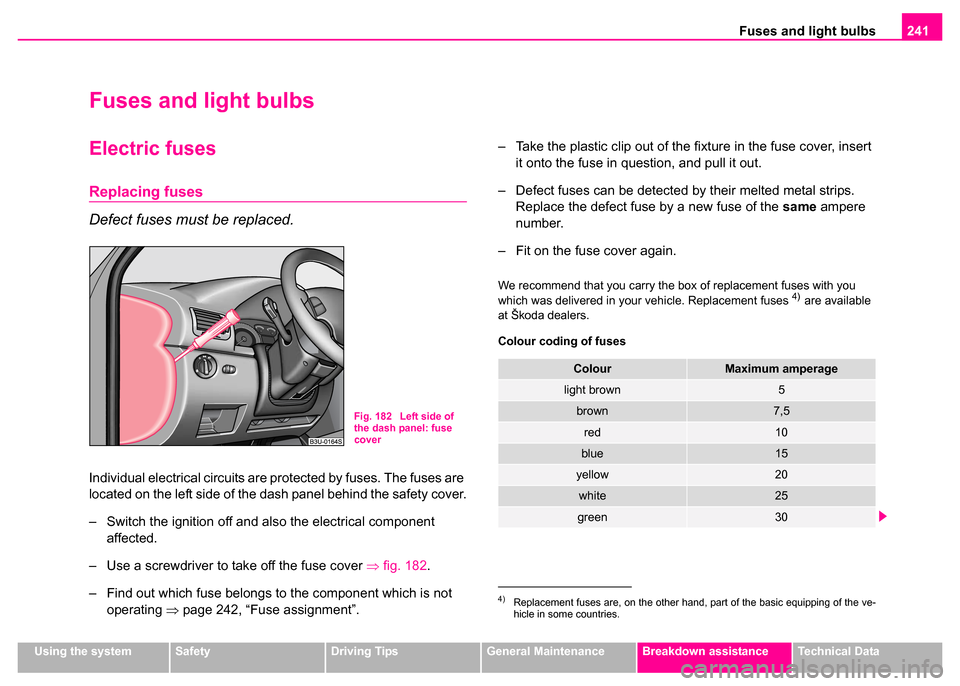
Individual electrical circuits are protected by fuses. The fuses are
located on the left side of the dash panel behind the safety cover.
– Switch the ignition off and also the electrical component
affected.
– Use a screwdriver to take off the fuse cover ⇒fig. 182.
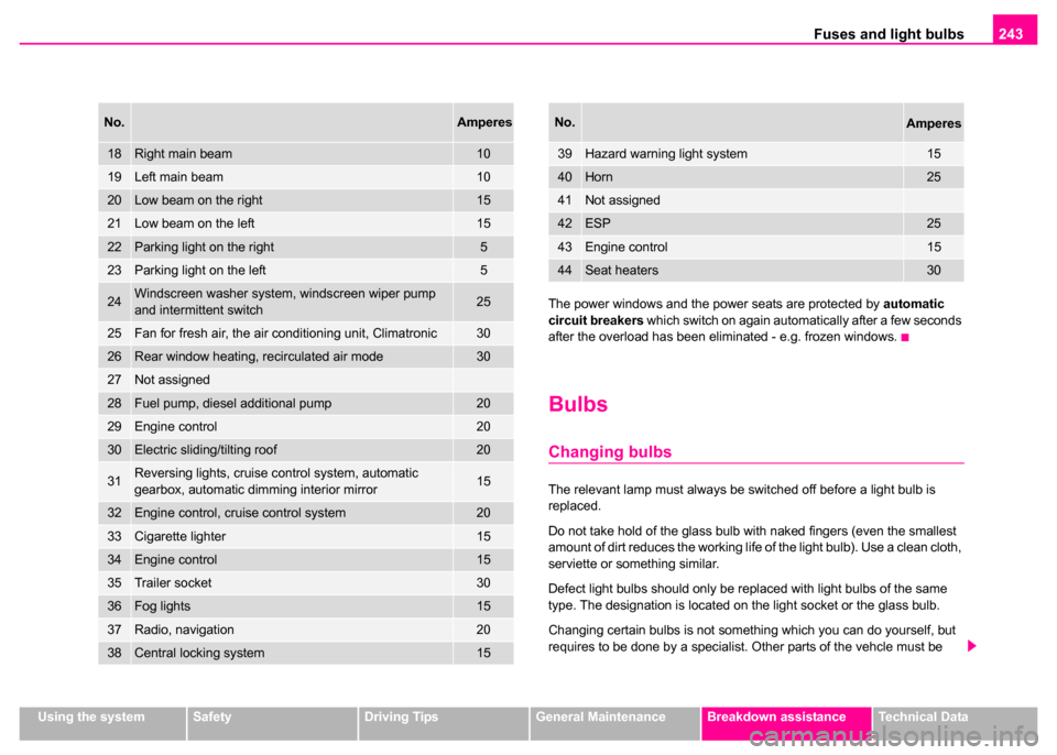
– Find out which fuse belongs to the component which is not operating ⇒page 242, “Fuse assignment”. – Take the plastic clip out of the fixture in the fuse cover, insert
it onto the fuse in question, and pull it out.
– Defect fuses can be detected by their melted metal strips. Replace the defect fuse by a new fuse of the same ampere
number.
– Fit on the fuse cover again.
We recommend that you carry the box of replacement fuses with you
which was delivered in your vehicle. Replacement fuses 4) are available
at Škoda dealers.
Colour coding of fuses
Fig. 182 Left side of
the dash panel: fuse
cover
4)Replacement fuses are, on the other hand, part of the basic equipping of the ve-
hicle in some countries.
ColourMaximum amperage
light brown5
brown7,5
red10
blue15
yellow20
white25
green30
Page 244 of 259

Fuses and light bulbs243
Using the systemSafetyDriving TipsGeneral MaintenanceBreakdown assistanceTechnical Data
The power windows and the power seats are protected by
automatic
circuit breakers which switch on again automatically after a few seconds
after the overload has been eliminated - e.g. frozen windows.
Bulbs
Changing bulbs
The relevant lamp must always be switched off before a light bulb is
replaced.
Do not take hold of the glass bulb with naked fingers (even the smallest
amount of dirt reduces the working life of the light bulb). Use a clean cloth,
serviette or something similar.
Defect light bulbs should only be replaced with light bulbs of the same
type. The designation is located on the light socket or the glass bulb.
Changing certain bulbs is not something which you can do yourself, but
requires to be done by a specialist. Other parts of the vehcle must be
18Right main beam10
19Left main beam10
20Low beam on the right15
21Low beam on the left15
22Parking light on the right5
23Parking light on the left5
24Windscreen washer system, windscreen wiper pump
and intermittent switch25
25Fan for fresh air, the air conditioning unit, Climatronic30
26Rear window heating, recirculated air mode30
27Not assigned
28Fuel pump, diesel additional pump20
29Engine control20
30Electric sliding/tilting roof20
31Reversing lights, cruise control system, automatic
gearbox, automatic dimming interior mirror15
32Engine control, cruise control system20
33Cigarette lighter15
34Engine control15
35Trailer socket30
36Fog lights15
37Radio, navigation 20
38Central locking system15
No.Amperes
39Hazard warning light system15
40Horn25
41Not assigned
42ESP25
43Engine control15
44Seat heaters30
No.Amperes
Page 246 of 259

Fuses and light bulbs245
Using the systemSafetyDriving TipsGeneral MaintenanceBreakdown assistanceTechnical Data
Note
This Owner's Manual only describes the replacement of bulbs where it is
assumed that no major complications will arise. Other light bulbs should
be changed by your Škoda dealer.
Rear light unit
– Open the boot lid/luggage compartment door.
– Raise the floor covering.
– Press the catch in direction of arrow and pull out the light
fixture.
– Press the defect light bulb in to the holder, turn anti-clockwise and remove. – Insert the new light bulb and turn it fully to the right.
– Insert the light bulb holder again, the plastic tongue must lock
in place.
Licence plate light
– Open the boot lid/luggage compartment door.
– Unscrew the glass cover of the light ⇒fig. 185.
– Take the faulty bulb out of the fixture and insert a new one.
– Replace the the glass cover of the light and press it down to the stop - ensure that the glass cover is correctly installed.
– Screw the glass cover tight.
Fig. 184 Luggage
compartment: Remove
light bulb holderFig. 185 Luggage
compartment door
Licence plate light
Page 248 of 259

Fuses and light bulbs247
Using the systemSafetyDriving TipsGeneral MaintenanceBreakdown assistanceTechnical Data
Changing the bulb for interior light of vehicles without an
electric sliding/tilting roof
– Insert a small screwdriver into the slot next to the light
⇒page 246, fig. 187.
– Carefully press out the light and remove it from the headliner.
– Take the faulty bulb out of and insert a new one.
– First of all place the lights in the mounts at the rear and press them into the headliner, until they lock into place.
Changing the bulb for interior light of vehicles with an
electric sliding/tilting roof
– Position a small screwdriver carefully against the rear edge of the cover of the power roof drive - arrows 1- ⇒page 246,
fig. 188 .
– Lever off the cover down carefully.
– Insert a small screwdriver into the slot next to the light - arrow 2-.
– Carefully press out the light and remove it from the headliner.
– Take the faulty bulb out of and insert a new one.
– First of all place the lights in the side plastic mounts and press them upwards, until they lock into place.
– Press on the cover again by first of all inserting the plastic lugs and then pushing the cover up.Interior lights at the rear
Changing the bulb for lights without interior monitoring
sensors
– Insert a small screwdriver into the slot next to the light cover ⇒fig. 189 and carefully lever the cover off.
– Take the faulty bulb out of and insert a new one.
– Insert the cover and press it in fully until it locks in place.
Changing the bulb for lights with interior monitoring
sensors
– We recommend having these bulbs replaced by a Škoda dealer.
Fig. 189 The interior
light at the rear without
interior monitoring
sensors
Page 250 of 259

General249
Using the systemSafetyDriving TipsGeneral MaintenanceBreakdown assistanceTechnical Data
Technical Data
General
Vehicle identification data
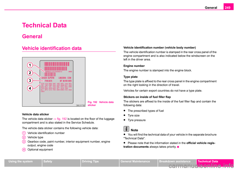
Vehicle data sticker
The vehicle data sticker ⇒fig. 192 is located on the floor of the luggage
compartment and is also stated in the Service Schedule.
The vehicle data sticker contains the following vehicle data:
Vehicle identification number
Vehicle type
Gearbox code, paint number, interior equipment number, engine
output, engine code
Optional equipment Vehicle identification number (vehicle body number)
The vehicle identification number is stamped in the rear cross panel of the
engine compartment and is also indicated below the windscreen on the
left in the driver area.
Engine number
The engine number is stamped into the engine block.
Ty p e p l a t e
The type plate is affixed to the rear cross panel in the engine compartment
on the right looking in the direction of travel.
Vehicles for certain export countries do not have a type plate.
Stickers on inside of fuel filler flap
The stickers are affixed to the inside of the fuel filler flap and contain the
following data:•The prescribed types of fuel
•Tyre size
•Tyre pressure
Note
•You will find the technical data of your vehicle in the separate brochure
"Technical Data".
•Please note that the information stated in the official vehicle regis-
tration documents always takes priority.
Fig. 192 Vehicle data
sticker
A1
A2
A3
A4
Page 256 of 259

Index255
Starting engine . . . . . . . . . . . . . . . . . . . . . . 115
after fuel tank has run empty . . . . . . . . . 117
Diesel engine . . . . . . . . . . . . . . . . . . . . . 116
Petrol engine . . . . . . . . . . . . . . . . . . . . . 116
Storage compartment Door trim panels . . . . . . . . . . . . . . . . . . . . 98
Lighting . . . . . . . . . . . . . . . . . . . . . . . . . . 60
Umbrella . . . . . . . . . . . . . . . . . . . . . . . . . . 99
Storage compartments . . . . . . . . . . . . . . . . . 95
Storage drawer . . . . . . . . . . . . . . . . . . . . . . . 96
Storage facilities . . . . . . . . . . . . . . . . . . . . . . 95
Stowage compartment below steering wheel 98
Sun visors . . . . . . . . . . . . . . . . . . . . . . . . . . . 63
Switch on the driver's door Power windows . . . . . . . . . . . . . . . . . . . . 49
Switching the engine off . . . . . . . . . . . . . . . 117
T
Taking care of your vehicle . . . . . . . . . . . . . 189
TCS Warning light . . . . . . . . . . . . . . . . . . . . . . 34
Telephone . . . . . . . . . . . . . . . . . . . . . . . . . . 132
The air conditioning system . . . . . . . . . . . . . 102
The armrest at the rear . . . . . . . . . . . . . . . . 101
The automatic wiper/washer system . . . . . . . 64 The battery . . . . . . . . . . . . . . . . . . . . . . . . . . 212
changing . . . . . . . . . . . . . . . . . . . . . . . . . 216
charging . . . . . . . . . . . . . . . . . . . . . . . . . 214
disconnecting and connecting . . . . . . . . 216
Inspecting the electrolyte level . . . . . . . . 214
Operation in winter . . . . . . . . . . . . . . . . . 214
The electronic immobiliser . . . . . . . . . . . . 35, 39
The radiator fan . . . . . . . . . . . . . . . . . . . . . . 210
The roof luggage rack system . . . . . . . . . . . . 88
Thickness of brake pads Warning light . . . . . . . . . . . . . . . . . . . . . . 32
Through-loading bag . . . . . . . . . . . . . . . . . . . 81
Tiptronic . . . . . . . . . . . . . . . . . . . . . . . . . . . . 123
Tool . . . . . . . . . . . . . . . . . . . . . . . . . . . . . . . 228
Towing a vehicle . . . . . . . . . . . . . . . . . . . . . 238
Towing eye at the front . . . . . . . . . . . . . . . . . . . . . . . 239
at the rear . . . . . . . . . . . . . . . . . . . . . . . . 239
Tow-starting a vehicle . . . . . . . . . . . . . . . . . 238
Tow-starting and towing vehicle Automatic gearbox . . . . . . . . . . . . . . . . . 129
Traction Control System Operating principle . . . . . . . . . . . . . . . . . 170
Trailer . . . . . . . . . . . . . . . . . . . . . . . . . . . . . . 184 Driving Tips . . . . . . . . . . . . . . . . . . . . . . 185
General Maintenance . . . . . . . . . . . . . . . 184
technical aspects . . . . . . . . . . . . . . . . . . 184
Transporting children . . . . . . . . . . . . . . . . . . 157
Tread depth . . . . . . . . . . . . . . . . . . . . . . . . . 221
Trip counter for distance driven . . . . . . . . . . . 16 Turn signal system for vehicles towing a trailer
Warning light . . . . . . . . . . . . . . . . . . . . . . . 30
Turn signals Warning light . . . . . . . . . . . . . . . . . . . . . . . 29
Two-way radio sets . . . . . . . . . . . . . . . . . . . 135
Two-way radio systems mobile . . . . . . . . . . . . . . . . . . . . . . . . . . . 135
Type plate . . . . . . . . . . . . . . . . . . . . . . . . . . 249
Tyres . . . . . . . . . . . . . . . . . . . . . . . . . . . . . . 220
U
Underbody protection . . . . . . . . . . . . . . . . . . 193
Unlocking . . . . . . . . . . . . . . . . . . . . . . . . . . . . 39 Remote control . . . . . . . . . . . . . . . . . . . . . 46
V
Vanity mirror . . . . . . . . . . . . . . . . . . . . . . . . . . 63
Vehicle electrics . . . . . . . . . . . . . . . . . . . . . . . 36
Vehicle identification data . . . . . . . . . . . . . . 249
Vehicle tool kit . . . . . . . . . . . . . . . . . . . . . . . 228
W
Warning lights . . . . . . . . . . . . . . . . . . . . . . . . 28
Warning symbols on the instrument cluster . . 28
Warning triangle . . . . . . . . . . . . . . . . . . . . . . 227
WashingWash systems . . . . . . . . . . . . . . . . . . . . 190
with high-pressure cleaner . . . . . . . . . . . 191