engine SKODA SUPERB 2003 1.G / (B5/3U) Owner's Manual
[x] Cancel search | Manufacturer: SKODA, Model Year: 2003, Model line: SUPERB, Model: SKODA SUPERB 2003 1.G / (B5/3U)Pages: 259
Page 2 of 259
Introduction
You have opted for a Škoda - our sincere thanks for your confidence in us.
Your new Škoda offers you a vehicle featuring the most modern engineering and a wide range of equipment
which you will undoubtedly wish to use to the full during your daily motoring. We therefore recommend that
you read this Owner's Manual attentively to enable you to become familiar with your vehicle and all that it
offers as quickly as possible.
Please do not hesitate to contact your Škoda dealer or importer should you have any further questions
regarding your vehicle or any problems which may arise. He will be ready at any time to receive your ques-
tions, suggestions and criticisms.
Any national legal provisions which vary from the information contained in this Owner's Manual take prec-
edence over the information contained herein.
We wish you much pleasure with your Škoda and pleasant motoring at all times.
Your Škoda Auto
Page 4 of 259
Contents3
Contents
Layout of this Owner's
Manual
. . . . . . . . . . . . . . . . . . . . . . . . . . . . .
Using the system . . . . . . . . . . . . . . .
Cockpit . . . . . . . . . . . . . . . . . . . . . . . . . . . . . . .
An overview . . . . . . . . . . . . . . . . . . . . . . . . . .
Instruments and Indicator/Warning LightsGeneral view of the instrument cluster . . . . . .
Engine revolutions counter . . . . . . . . . . . . . . .
Coolant temperature gauge . . . . . . . . . . . . . .
Fuel gauge . . . . . . . . . . . . . . . . . . . . . . . . . . .
Digital clock . . . . . . . . . . . . . . . . . . . . . . . . . .
Speedometer with counter for distance driven
Service Interval Display . . . . . . . . . . . . . . . . .
Multi-functional indicator* . . . . . . . . . . . . . . . .
Information display* . . . . . . . . . . . . . . . . . . . .
Auto Check Control . . . . . . . . . . . . . . . . . . . .
Warning lights . . . . . . . . . . . . . . . . . . . . . . . . .
Unlocking and locking . . . . . . . . . . . . . . . . . .
Keys . . . . . . . . . . . . . . . . . . . . . . . . . . . . . . . .
Central locking system . . . . . . . . . . . . . . . . . .
Child safety locks . . . . . . . . . . . . . . . . . . . . . .
Remote control . . . . . . . . . . . . . . . . . . . . . . . .
Anti-theft alarm system . . . . . . . . . . . . . . . . . .
Power windows . . . . . . . . . . . . . . . . . . . . . . .
Electric sliding/tilting roof* . . . . . . . . . . . . . . .
Lights and Visibility. . . . . . . . . . . . . . . . . . . . .
Lights . . . . . . . . . . . . . . . . . . . . . . . . . . . . . . .
Interior lighting . . . . . . . . . . . . . . . . . . . . . . . .
Visibility . . . . . . . . . . . . . . . . . . . . . . . . . . . . . The windscreen wiper and washing system .
Rear-view mirror . . . . . . . . . . . . . . . . . . . . . .
Seats and Stowage . . . . . . . . . . . . . . . . . . . .
Front seats . . . . . . . . . . . . . . . . . . . . . . . . . . .
Adjusting front seats manually . . . . . . . . . . . .
Adjusting front seats electrically* . . . . . . . . . .
Front passenger seat with a folding central back
rest* . . . . . . . . . . . . . . . . . . . . . . . . . . . . . . . .
Footrest at the rear* . . . . . . . . . . . . . . . . . . . .
Seat heaters* . . . . . . . . . . . . . . . . . . . . . . . . .
Pedals . . . . . . . . . . . . . . . . . . . . . . . . . . . . . .
Luggage compartment . . . . . . . . . . . . . . . . . .
The cool box in the armrest of rear seats* . . .
CargoFlex folding box* . . . . . . . . . . . . . . . . . .
The roof luggage rack system . . . . . . . . . . . .
Drinks can holder . . . . . . . . . . . . . . . . . . . . . .
Ashtray . . . . . . . . . . . . . . . . . . . . . . . . . . . . . .
Cigarette lighters and power sockets . . . . . . .
Storage facilities . . . . . . . . . . . . . . . . . . . . . . .
Heating and air conditioning system . . . . .
The air conditioning system . . . . . . . . . . . . . .
Climatronic* (automatic air conditioning) . . . .
Starting-off and Driving. . . . . . . . . . . . . . . . .
Setting steering wheel position . . . . . . . . . . .
Ignition lock . . . . . . . . . . . . . . . . . . . . . . . . . .
Starting engine . . . . . . . . . . . . . . . . . . . . . . . .
Switching the engine off . . . . . . . . . . . . . . . . .
Shifting gears . . . . . . . . . . . . . . . . . . . . . . . . .
Handbrake . . . . . . . . . . . . . . . . . . . . . . . . . . .
Parking aid* . . . . . . . . . . . . . . . . . . . . . . . . . .
Cruise control system (CCS)* . . . . . . . . . . . .
Automatic gearbox*. . . . . . . . . . . . . . . . . . . .
5-speed automatic gearbox . . . . . . . . . . . . . .
Communicating and Navigating . . . . . . . . .
Multifunction steering wheel* . . . . . . . . . . . . .
Mobile phone, two-way radio system and
navigation system . . . . . . . . . . . . . . . . . . . . .
Safety. . . . . . . . . . . . . . . . . . . . . . . . . . . . . .
Passive Safety . . . . . . . . . . . . . . . . . . . . . . . .
Driving the safe way . . . . . . . . . . . . . . . . . . .
Requirements for maximum safety . . . . . . . .
Seat belts. . . . . . . . . . . . . . . . . . . . . . . . . . . . .
Why seat belts? . . . . . . . . . . . . . . . . . . . . . . .
The physical principle of a frontal collision . .
Important safety information regarding the use
of seat belts . . . . . . . . . . . . . . . . . . . . . . . . . .
How are seat belts correctly fastened? . . . . .
Belt tensioners . . . . . . . . . . . . . . . . . . . . . . . .
Airbag system. . . . . . . . . . . . . . . . . . . . . . . . .
Description of the airbag system . . . . . . . . . .
Front airbags . . . . . . . . . . . . . . . . . . . . . . . . .
Side airbags . . . . . . . . . . . . . . . . . . . . . . . . . .
Head airbags* . . . . . . . . . . . . . . . . . . . . . . . .
Deactivating an airbag . . . . . . . . . . . . . . . . . .
Transporting children safely . . . . . . . . . . . .
What you should know about transporting
children! . . . . . . . . . . . . . . . . . . . . . . . . . . . . .
Child seat . . . . . . . . . . . . . . . . . . . . . . . . . . . .
Attaching child safety seat . . . . . . . . . . . . . . .
7
9
11
11
13
13
14
14
15
15
16
17
18
22
25
28
37
37
39
45
46
47
49
52
56
56
60
62 64
66
69
69
69
70
75
77
77
78
78
82
85
88
90
91
93
95
102
102
107 11 4
11 4
11 4
11 5
11 7
11 8
11 8
11 9
120
123
123 130
130
132
137
137
137
137
138
138
139
140
141
143
145
145
147
149
152
154
157
157
161
164
Page 5 of 259
Contents
4
Driving Tips . . . . . . . . . . . . . . . . . . . . . .
Intelligent Technology . . . . . . . . . . . . . . . . . .
Electronic stability programme (ESP)* . . . . . .
Brakes . . . . . . . . . . . . . . . . . . . . . . . . . . . . . .
Antilock brake system (ABS) . . . . . . . . . . . . .
Brake Assist* . . . . . . . . . . . . . . . . . . . . . . . . .
Power steering . . . . . . . . . . . . . . . . . . . . . . . .
Driving and the Environment. . . . . . . . . . . .
The first 1 500 kilometres and then afterwards
Catalytic converter . . . . . . . . . . . . . . . . . . . . .
Motoring abroad . . . . . . . . . . . . . . . . . . . . . . .
Avoiding damage to your vehicle . . . . . . . . . .
Driving in an economical and environmentally
conscious manner . . . . . . . . . . . . . . . . . . . . .
Environmental compatibility . . . . . . . . . . . . . .
Towing a trailer . . . . . . . . . . . . . . . . . . . . . . . .
Towing a trailer . . . . . . . . . . . . . . . . . . . . . . . .
Detachable towing device* . . . . . . . . . . . . . .
General Maintenance . . . . . . . . . .
Care and cleaning . . . . . . . . . . . . . . . . . . . . .
General . . . . . . . . . . . . . . . . . . . . . . . . . . . . .
Care of the exterior of vehicle . . . . . . . . . . . .
Care of the interior of vehicle . . . . . . . . . . . . .
Engine compartment . . . . . . . . . . . . . . . . . . .
Fuel. . . . . . . . . . . . . . . . . . . . . . . . . . . . . . . . . .
Petrol . . . . . . . . . . . . . . . . . . . . . . . . . . . . . . .
Diesel . . . . . . . . . . . . . . . . . . . . . . . . . . . . . . .
Refuelling . . . . . . . . . . . . . . . . . . . . . . . . . . . .
Inspecting and Replenishing. . . . . . . . . . . .
Engine compartment . . . . . . . . . . . . . . . . . . .
Overview of the engine compartment . . . . . .
Engine oil . . . . . . . . . . . . . . . . . . . . . . . . . . . .
Cooling system . . . . . . . . . . . . . . . . . . . . . . . Brake fluid . . . . . . . . . . . . . . . . . . . . . . . . . . .
The battery . . . . . . . . . . . . . . . . . . . . . . . . . .
Windscreen Wiper and Washer System . . . .
Spark plugs . . . . . . . . . . . . . . . . . . . . . . . . . .
V-ribbed belts . . . . . . . . . . . . . . . . . . . . . . . . .
The dust and pollen filter* . . . . . . . . . . . . . . .
Wheels and Tyres . . . . . . . . . . . . . . . . . . . . .
Wheels . . . . . . . . . . . . . . . . . . . . . . . . . . . . .
Accessories, changes and replacement of
parts . . . . . . . . . . . . . . . . . . . . . . . . . . . . . . . . .
General . . . . . . . . . . . . . . . . . . . . . . . . . . . . .
Breakdown assistance . . . . . . . .
Breakdown assistance . . . . . . . . . . . . . . . . .
First-aid box* . . . . . . . . . . . . . . . . . . . . . . . . .
Warning triangle . . . . . . . . . . . . . . . . . . . . . .
Fire extinguisher* . . . . . . . . . . . . . . . . . . . . . .
Vehicle tool kit . . . . . . . . . . . . . . . . . . . . . . . .
Spare wheel . . . . . . . . . . . . . . . . . . . . . . . . . .
Changing a wheel . . . . . . . . . . . . . . . . . . . . .
Jump-starting . . . . . . . . . . . . . . . . . . . . . . . . .
Tow-starting and towing vehicle . . . . . . . . . . .
Fuses and light bulbs . . . . . . . . . . . . . . . . . .
Electric fuses . . . . . . . . . . . . . . . . . . . . . . . . .
Bulbs . . . . . . . . . . . . . . . . . . . . . . . . . . . . . . .
Technical Data. . . . . . . . . . . . . . . . . . .
General . . . . . . . . . . . . . . . . . . . . . . . . . . . . . .
Vehicle identification data . . . . . . . . . . . . . . .
Index. . . . . . . . . . . . . . . . . . . . . . . . . . . . . . .
169
169
169
172
173
174
174
176
176
177
178
178
179
183
184
184
186
189
189
189
189
194
196
198
198
198
200
202
202
204
205
208 210
212
217
217
218
218
219
219
226
226
227
227
227
227
228
228
229
229
236
238
241
241
243
249
249
249
251
Page 14 of 259
Instruments and Indicator/Warning Lights13
Using the systemSafetyDriving TipsGeneral MaintenanceBreakdown assistanceTechnical Data
Instruments and Indicator/Warning Lights
General view of the instrument cluster
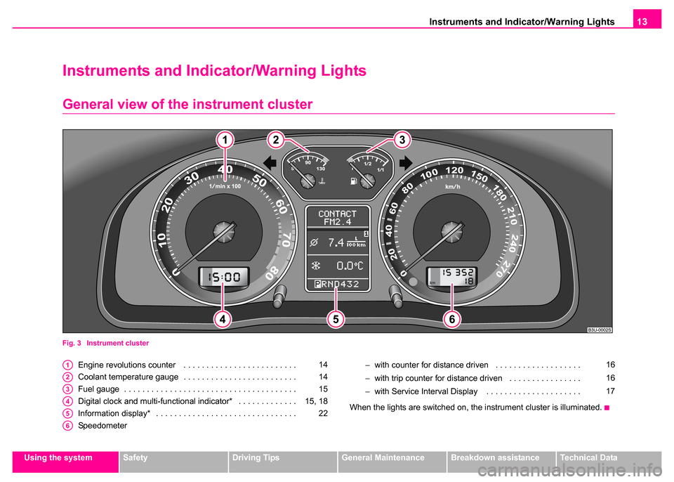
Fig. 3 Instrument cluster
Engine revolutions counter . . . . . . . . . . . . . . . . . . . . . . . . .
Coolant temperature gauge . . . . . . . . . . . . . . . . . . . . . . . . .
Fuel gauge . . . . . . . . . . . . . . . . . . . . . . . . . . . . . . . . . . . . . .
Digital clock and multi-functional indicator* . . . . . . . . . . . . .
Information display* . . . . . . . . . . . . . . . . . . . . . . . . . . . . . . .
Speedometer −
with counter for distance driven . . . . . . . . . . . . . . . . . . .
− with trip counter for distance driven . . . . . . . . . . . . . . . .
− with Service Interval Display . . . . . . . . . . . . . . . . . . . . .
When the lights are switched on, the instrument cluster is illuminated.A114
A214
A315
A415, 18
A522
A6
16
16
17
Page 15 of 259
Instruments and Indicator/Warning Lights
14
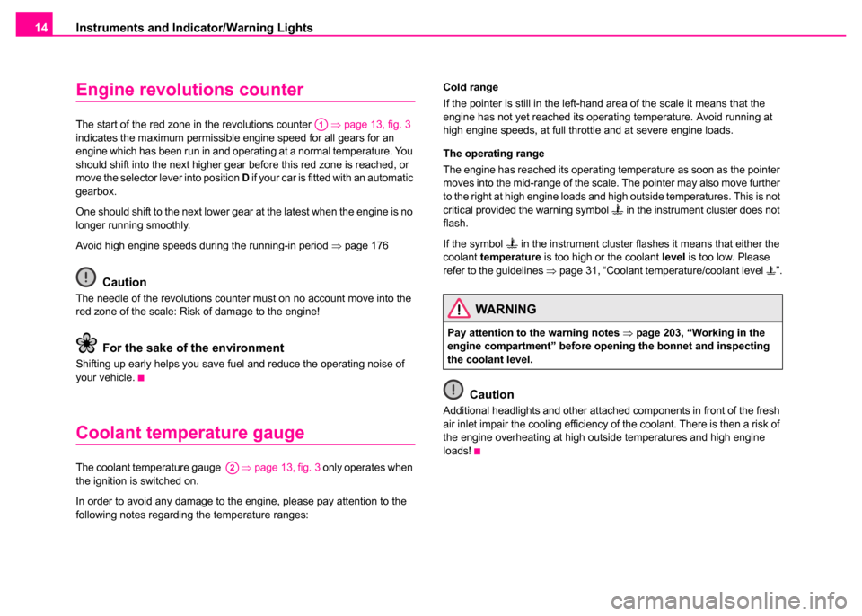
Engine revolutions counter
The start of the red zone in the revolutions counter ⇒page 13, fig. 3
indicates the maximum permissible engine speed for all gears for an
engine which has been run in and operating at a normal temperature. You
should shift into the next higher gear before this red zone is reached, or
move the selector lever into position D if your car is fitted with an automatic
gearbox.
One should shift to the next lower gear at the latest when the engine is no
longer running smoothly.
Avoid high engine speeds during the running-in period ⇒page 176
Caution
The needle of the revolutions counter must on no account move into the
red zone of the scale: Risk of damage to the engine!
For the sake of the environment
Shifting up early helps you save fuel and reduce the operating noise of
your vehicle.
Coolant temperature gauge
The coolant temperature gauge ⇒page 13, fig. 3 only operates when
the ignition is switched on.
In order to avoid any damage to the engine, please pay attention to the
following notes regarding the temperature ranges: Cold range
If the pointer is still in the left-hand area of the scale it means that the
engine has not yet reached its operating temperature. Avoid running at
high engine speeds, at full throttle and at severe engine loads.
The operating range
The engine has reached its operating temperature as soon as the pointer
moves into the mid-range of the scale. The pointer may also move further
to the right at high engine loads and high outside temperatures. This is not
critical provided the warning symbol
in the instrument cluster does not
flash.
If the symbol
in the instrument cluster flashes it means that either the
coolant temperature is too high or the coolant level is too low. Please
refer to the guidelines ⇒page 31, “Coolant temperature/coolant level ”.
Caution
Additional headlights and other attached components in front of the fresh
air inlet impair the cooling efficiency of the coolant. There is then a risk of
the engine overheating at high outside temperatures and high engine
loads!
A1
A2
WARNING
Pay attention to the warning notes ⇒page 203, “Working in the
engine compartment” before opening the bonnet and inspecting
the coolant level.
Page 18 of 259
Instruments and Indicator/Warning Lights17
Using the systemSafetyDriving TipsGeneral MaintenanceBreakdown assistanceTechnical Data
Service Interval Display
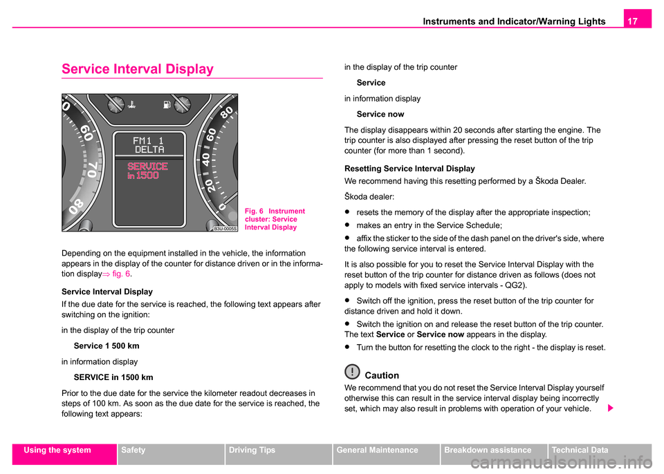
Depending on the equipment installed in the vehicle, the information
appears in the display of the counter for distance driven or in the informa-
tion display⇒fig. 6 .
Service Interval Display
If the due date for the service is reached, the following text appears after
switching on the ignition:
in the display of the trip counter Service 1 500 km
in information display SERVICE in 1500 km
Prior to the due date for the service the kilometer readout decreases in
steps of 100 km. As soon as the due date for the service is reached, the
following text appears: in the display of the trip counter
Service
in information display Service now
The display disappears within 20 seconds after starting the engine. The
trip counter is also displayed after pressing the reset button of the trip
counter (for more than 1 second).
Resetting Service Interval Display
We recommend having this resetting performed by a Škoda Dealer.
Škoda dealer:
•resets the memory of the display after the appropriate inspection;
•makes an entry in the Service Schedule;
•affix the sticker to the side of the dash panel on the driver's side, where
the following service interval is entered.
It is also possible for you to reset the Service Interval Display with the
reset button of the trip counter for distance driven as follows (does not
apply to models with fixed service intervals - QG2).
•Switch off the ignition, press the reset button of the trip counter for
distance driven and hold it down.
•Switch the ignition on and release the reset button of the trip counter.
The text Service or Service now appears in the display.
•Turn the button for resetting the clock to the right - the display is reset.
Caution
We recommend that you do not reset the Service Interval Display yourself
otherwise this can result in the service interval display being incorrectly
set, which may also result in problems with operation of your vehicle.
Fig. 6 Instrument
cluster: Service
Interval Display
Page 21 of 259
Instruments and Indicator/Warning Lights
20
Using the system
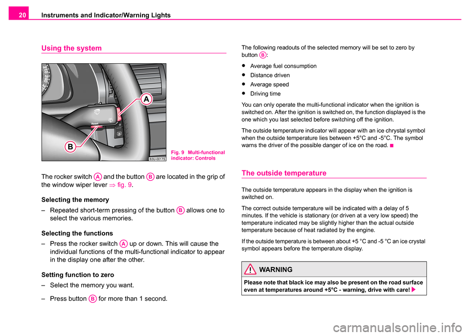
The rocker switch and the button are located in the grip of
the window wiper lever ⇒fig. 9 .
Selecting the memory
– Repeated short-term pressing of the button allows one to select the various memories.
Selecting the functions
– Press the rocker switch up or down. This will cause the individual functions of the multi-functional indicator to appear
in the display one after the other.
Setting function to zero
– Select the memory you want.
– Press button for more than 1 second.
The following readouts of the selected memory will be set to zero by
button :
•Average fuel consumption
•Distance driven
•Average speed
•Driving time
You can only operate the multi-functional indicator when the ignition is
switched on. After the ignition is switched on, the function displayed is the
one which you last selected before switching off the ignition.
The outside temperature indicator will appear with an ice chrystal symbol
when the outside temperature lies between +5°C and -5°C. The symbol
warns the driver of the possible danger of ice on the road.
The outside temperature
The outside temperature appears in the display when the ignition is
switched on.
The correct outside temperature will be indicated with a delay of 5
minutes. If the vehicle is stationary (or driven at a very low speed) the
temperature indicated may be slightly higher than the actual outside
temperature because of heat radiated by the engine.
If the outside temperature is between about +5 °C and -5 °C an ice crystal
symbol appears before the temperature display.
Fig. 9 Multi-functional
indicator: Controls
AAAB
AB
AA
AB
WARNING
Please note that black ice may also be present on the road surface
even at temperatures around +5°C - warning, drive with care!
AB
Page 27 of 259
Instruments and Indicator/Warning Lights
26
If the Auto Check Control detects faults, these will be displayed about 15
seconds after starting the engine in place of the text shown above. A
warning signal sounds at the same time.
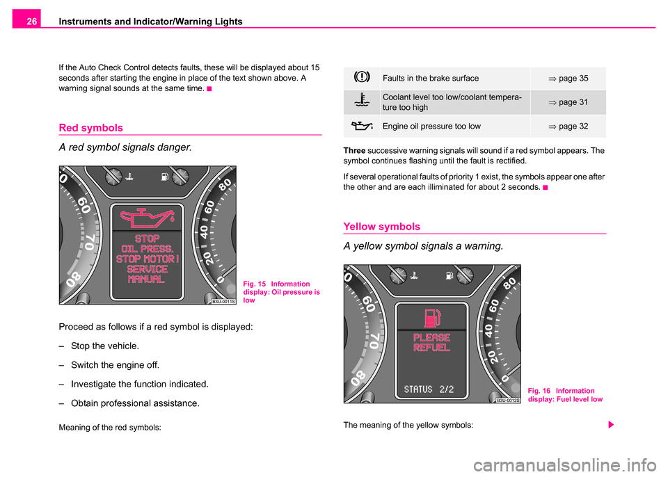
Red symbols
A red symbol signals danger.
Proceed as follows if a red symbol is displayed:
– Stop the vehicle.
– Switch the engine off.
– Investigate the function indicated.
– Obtain professional assistance.
Meaning of the red symbols: Three
successive warning signals will sound if a red symbol appears. The
symbol continues flashing until the fault is rectified.
If several operational faults of priority 1 exist, the symbols appear one after
the other and are each illiminated for about 2 seconds.
Yellow symbols
A yellow symbol signals a warning.
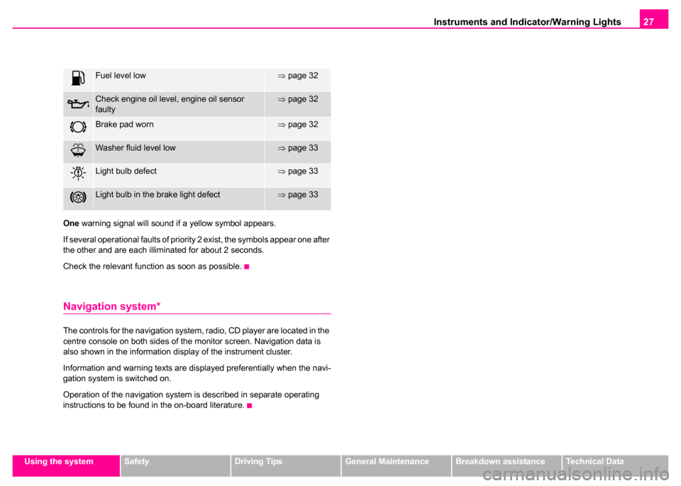
The meaning of the yellow symbols:
Fig. 15 Information
display: Oil pressure is
low
Faults in the brake surface⇒ page 35
Coolant level too low/coolant tempera-
ture too high⇒page 31
Engine oil pressure too low⇒page 32
Fig. 16 Information
display: Fuel level low
Page 28 of 259
Instruments and Indicator/Warning Lights27
Using the systemSafetyDriving TipsGeneral MaintenanceBreakdown assistanceTechnical Data
One
warning signal will sound if a yellow symbol appears.
If several operational faults of priority 2 exist, the symbols appear one after
the other and are each illiminated for about 2 seconds.
Check the relevant function as soon as possible.
Navigation system*
The controls for the navigation system, radio, CD player are located in the
centre console on both sides of the monitor screen. Navigation data is
also shown in the information display of the instrument cluster.
Information and warning texts are displayed preferentially when the navi-
gation system is switched on.
Operation of the navigation system is described in separate operating
instructions to be found in the on-board literature.
Fuel level low⇒ page 32
Check engine oil level, engine oil sensor
faulty⇒page 32
Brake pad worn⇒page 32
Washer fluid level low⇒page 33
Light bulb defect⇒page 33
Light bulb in the brake light defect⇒page 33
Page 30 of 259
Instruments and Indicator/Warning Lights29
Using the systemSafetyDriving TipsGeneral MaintenanceBreakdown assistanceTechnical Data
Note
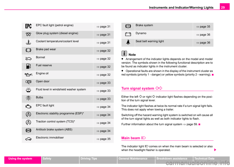
•Arrangement of the indicator lights depends on the model and model
version. The symbols shown in the following functional description are to
be found as indicator lights in the instrument cluster.
•Operational faults are shown in the display of the instrument cluster as
red symbols (priority 1 - danger) or yellow symbols (priority 2 - warning).
Turn signal system
Either the left or right indicator light flashes depending on the posi-
tion of the turn signal lever.
The indicator light flashes at twice its normal rate if a turn signal light fails.
This does not apply when towing a trailer.
Switching off the hazard warning light system is switched on will cause all
of the turn signal lights as well as both indicator lights to flash.
Further information about the turn signal system ⇒page 59.
Main beam
The indicator light comes on when the main beam is selected or also
when the headlight flasher is operated.
EPC fault light (petrol engine)⇒ page 31
Glow plug system (diesel engine)⇒page 31
Coolant temperature/coolant level⇒page 31
Brake pad wear⇒page 32
Bonnet⇒page 32
Fuel reserve⇒page 32
Engine oil⇒page 32
Open door⇒page 33
Fluid level in windshield washer system⇒page 33
Bulbs⇒page 33
EPC fault light⇒page 34
Electronic stability programme (ESP)*⇒page 34
Traction control system (TCS)*⇒page 34
Antilock brake system (ABS)⇒page 34
Electronic immobiliser⇒page 35
Brake system⇒page 35
Dynamo⇒page 36
Seat belt warning light⇒page 36