ECO mode SKODA SUPERB 2006 1.G / (B5/3U) Owner's Manual
[x] Cancel search | Manufacturer: SKODA, Model Year: 2006, Model line: SUPERB, Model: SKODA SUPERB 2006 1.G / (B5/3U)Pages: 281, PDF Size: 12.67 MB
Page 2 of 281
Introduction
You have opted for a Škoda - our sincere thanks for your confidence in us.
Your new Škoda offers you a vehicle featuring the most modern engineering and a wide range of equipment
which you will undoubtedly wish to use to the full during your daily motoring. That is why, we recommend
that you read this Owner's Manual attentively to enable you to become familiar with your car and all that it
offers as quickly as possible.
Please do not hesitate to contact your Škoda Service Partner or importer should you have any further ques-
tions regarding any problems which may arise or your vehicle. He will be ready at any time to receive your
questions, suggestions and criticisms.
Any national legal provisions which vary from the information contained in this Owner's Manual take prec-
edence over the information contained herein.
We wish you much pleasure with your Škoda and pleasant motoring at all times.
Your Škoda Auto
NKO B5 20.book Page 1 Monday, July 3, 2006 2:09 PM
Page 3 of 281
Introduction
2
On-board literature
The on-board literature for your vehicle consists of this “ Owner's
Manual” as well as the brochures “ Service schedule”, “Brief
instruction ”, “Te c h n i c a l d a t a ” and “Help on the road ”. There
can also be a variety of other additional operating manuals and
instructions on-board (e.g. an operating manual for the radio)
depending on the vehicle model and equipment.
If one of the publications listed above is missing, please contact
a Škoda Service Partner immediately, where one will be glad to
assist you in such matters.
One should note that the details given in the vehicle's papers
always take precedence over th ose in the Owner's Manual.
Owner's Manual
This Owner's Manual describes the current scope of equip-
ment . Certain items of equipment listed are only installed later on
and only envisaged for particular markets. The illustrations can
differ in minor details from your vehicle; they are only intended for
general information.
In addition to information regarding all the controls and equip-
ment, the Owner's Manual also contains important information
regarding care and operation for your safety and also to retain the
value of your vehicle. To provide you with valuable tips and aids.
You can learn how how you can operate your vehicle safely,
economically and in an environmentally conscious way.
For safety reasons, please also pay attention to the informa-
tion on accessories, modificati ons and replacement of parts
⇒ page 242. The other chapters of the Owner's Manual are also important,
however, for proper treatment of your car - in addition to regular
care and maintenance - helps to retain its value and in many
cases is also one of the conditions for possible warranty claims.
The Brief instruction
includes an overview of the most important controls of your
vehicle.
The Service schedule
contains:
•Vehicle data,
•Service intervals,
•Overview of the service work,
•Service proof,
•Confirmation of mobility warranty,
•important information on the warranty.
The confirmations of the carried out service work are one of the
conditions for possible warranty claims.
Please always present the Service schedule when you take your
car to a Škoda Service Partner.
If the Service schedule is missing or worn, please contact your
Škoda Service Partner, where your car is serviced regularly. You
will receive a duplicate, in which the previously carried out
service work are confirmed.
Help on the road
contains the addresses and telephone numbers of Škoda
Importers.
NKO B5 20.book Page 2 Monday, July 3, 2006 2:09 PM
Page 18 of 281
Instruments and Indicator/Warning Lights17
Using the systemSafetyDriving TipsGeneral MaintenanceBreakdown assistanceTechnical Data
Depending on the equipment installed in the vehicle, the information
appears in the display of the counter for distance driven or in the informa-
tion display
⇒page 16, fig. 5 .
Service Interval Display
If the due date for the service is reached, the following text appears after
switching on the ignition:
in the display of the trip counter Service 1 500 km
in information display SERVICE in 1500 km
Prior to the due date for the service the kilometre readout decreases in
steps of 100 km. As soon as the due date for the service is reached, the
following text appears:
in the display of the trip counter Service
in information display SERVICE NOW
The display disappears within 20 seconds after starting the engine. The
trip counter is also displayed after pressing the reset button of the trip
counter (for more than 1 second).
Resetting Service Interval Display
We recommend having this resetting performed by a specialist garage.
The specialist garage:
•resets the memory of the display after the appropriate inspection,
•makes an entry in the Service schedule,
•affix the sticker with the entry of the following service interval to the
side of the dash panel on the driver's side. It is also possible for you to reset the Service Interval Display with the
reset button
⇒page 16, fig. 5 as follows (does not apply to models
with fixed service intervals - QG2).
•Switch off the ignition (if not already off), press the reset button and
hold it down.
•Switch the ignition on and release the reset button . The text
Service or service now appears in the display.
•Turn the button for resetting the clock to the right - the display is
reset.
Caution
We recommend that you do not reset the Service Interval Display yourself
otherwise this can result in the service interval display being incorrectly
set, which may also result in problems with operation of your vehicle.
Note
•Never reset the display between service intervals otherwise this may
result in incorrect readouts.
•Information is retained in the Service Interval Display also after the
battery of the vehicle is disconnected.
•It is necessary to re-code the Service Interval Display if a new instru-
ment cluster is installed during repair work. This work is carried out by a
specialist garage.
•After resetting the display with flexible service intervals (QG1) using
the reset button , the data displayed are the same as for a car with fixed
service intervals (QG2). We therefore recommend having the Service
Interval Display reset only by a Škoda Service Partner who is familiar with
the procedure for resetting the display with a vehicle system tester.
•Please refer to the brochure Service schedule for extensive informa-
tion about the service intervals.
AB
AB
AB
AA
AB
NKO B5 20.book Page 17 Monday, July 3, 2006 2:09 PM
Page 32 of 281
Instruments and Indicator/Warning Lights31
Using the systemSafetyDriving TipsGeneral MaintenanceBreakdown assistanceTechnical Data
tion procedure lasts about 2 to 3 minutes and is performed without driver
interference.
If the engine control unit detects that the operating conditions for a regen-
eration (combustion of deposited soot particles) of the diesel particle fiter
are not optimal, e.g. slow city driving, a warning light in the instrument
cluster is illuminated
. In order to clean the diesel particle filter, the
vehicle should be driven at an even speed of at least 60 km/h for approx.
5 - 10 minutes. The diesel particle filter is most effectively cleaned if the
vehicle is driven in the 4th or 5th gear within the range of 2 000 to 3 000
rpm.
If these conditions are not met, the warning light
does not go out and
after 10 minutes the warning light begins to flash. ENGINE
WORKSHOP! is shown in the information display*. Afterwards the engine
control unit shifts the engine into the emergency mode, which only has a
reduced power output. After switching the ignition off and on again the
warning light
comes on.
Have the vehicle inspected without delay by your specialist garage.
WARNING
•Please pay attention to the traffic regulations and speed limits.
•The diesel particle filter achieves very high temperatures.
Therefore do not park at points where the hot filter comes into
direct contact with dry grass or other combustible materials - risk
of fire!
•Use neither protective paint for chassis nor anti-corrosion
agent, in order to treat the exhaust system, the heat shields or the
diesel particle filter. The high temperatures can cause the coating
to ignite!
Note
•The servicing of the diesel particle filter and the replenishing of the
additive are performed by a specialist garage in the framework of the
regular inspection, see Service shedule.
•It is prohibited to use biofuel (RME) and diesel fuel mixture for diesel
vehicles which are fitted with diesel particle filter.
Glow plug system (diesel engine)
The indicator light lights up for a cold engine when switching on the
ignition (pre-heat position) 2 ⇒ page 121. Start the engine just as soon as
the indicator light goes out.
The glow plug indicator light will come on for about 1 second if the engine
is at a normal operating temperature or if the outside temperature is
above +5°C. This means that you can start the engine right away.
There is a fault in the glow plug system if the indicator light
does not
come on at all or lights up continuously. Contact a specialist garage as
soon as possible to obtain assistance.
There is a system fault in the engine control system if the warning light
has started to flash while driving. The engine management system selects
an emergency programme which enables you to drive to the nearest
specialist garage by adopting a gentle style of driving.
The following text will be displayed in the information display*:
ENGINE WORKSHOP! (ENGINE FAULT WORKSHOP!)
NKO B5 20.book Page 31 Monday, July 3, 2006 2:09 PM
Page 42 of 281
Unlocking and locking41
Using the systemSafetyDriving TipsGeneral MaintenanceBreakdown assistanceTechnical Data
So long as the child safety lock is switched on it is not possible to open the
door from the inside with the door opening lever. In this case the door can
be opened only from the outside.
Central locking system
Description
Unlocking or locking the vehicle causes
all doors to be unlocked or locked
at the same time by the central locking system. The boot lid is unlocked
when opening. It can be opened by pressing the hand grip above the
licence plate.
Operation of the central locking system is possible:
•from the outside using the vehicle key ⇒page 42
•using the buttons for the central locking system ⇒page 43
•by using the radio remote control ⇒page 46
Convenience operation of windows
One can open and close the electrically powered windows when unlocking
and locking the vehicle ⇒page 51, “Window convenience operation”. The
electric sliding/tilting roof* can only be closed by the central locking
system.
Opening a single door*
This function allows one to just unlock the driver's door. The other doors
remain locked and are only unlocked when the command is repeated. The
single door opening function can be first activated by recoding the control
unit of the central locking system. This work is undertaken by a Škoda
Service Partner can give you more information. Automatic locking*
All the doors and the boot lid are locked automatically once the car
reaches a speed of about 15 km/h.
If the ignition key is withdrawn, the car is then automatically unlocked
again. In addition, it is possible for the driver to unlock the car by pressing
the central locking button
or by pulling the door opening lever.
If you wish, your Škoda Service Partner can convert the central locking
system of your car to the automatic locking mode.
WARNING
Locking the doors prevents involuntary opening in an exceptional
situation (an accident). Locked doors prevent unwanted entry into
the vehicle from outside, for example at road crossings. Locked
doors do, however, make it more difficult for rescuers to get into
the vehicle in an emergency - danger to life!
Note
•After unlocking the vehicle see, if the securing knobs are located on all
doors at the bottom.
•In the event of an accident in which the airbags are deployed, the
locked doors are automatically unlocked in order to enable rescuers to
gain access to the vehicle.
•Should the central locking system not operate properly, you can lock
and unlock the front doors and the boot lid with the key. Emergency
unlocking of fuel filler flap ⇒page 217.
NKO B5 20.book Page 41 Monday, July 3, 2006 2:09 PM
Page 54 of 281

Unlocking and locking53
Using the systemSafetyDriving TipsGeneral MaintenanceBreakdown assistanceTechnical Data
The sliding/tilting roof is operated by means of the control dial
⇒fig. 32
and only functions when the ignition is switched on. The control dial has a
number of fixed positions.
After switching the ignition off, it is still possible to open or close the
sliding/tilting roof for a further 10 minutes. It is no longer possible to
operate the sliding/tilting roof after opening or closing one of the front
doors, however.
Note
•If the battery has been disconnected and reconnected, it is possible
that the sliding/tilting roof does not close fully. Here you have to set the
control dial to the switch position and press it forward for about 10
seconds.
•It is necessary after each emergency operation (using crank handle)
to move the sliding/tilting roof into the basic position. Here you have to set
the control dial to the switch position and press it forward for about 10
seconds.
Opening and tilting
Comfort position
– Turn the switch to position ⇒page 52, fig. 32 .
Opening roof fully
– Turn the switch to position and hold it in this position (spring-tensioned position).
Tilting roof
– Turn the switch to position .
The wind noise in the comfort position is less than when the roof is fully
opened.
The sun screen is also opened automatically when the roof slides open.
You can slide the sun screen into the opened or closed position by hand
when the sliding/tilting roof is closed. (This does not apply for models fitted
with sliding/tilting roof with solar cells, in which the sun screen is a fixed
element.)
Caution
It may be necessary during winter to remove any ice and snow in the area
of the sliding/tilting roof before opening it in order to prevent damaging the
opening mechanism.
Closing
Sliding closed/closing the sliding/tilting roof
– Turn the switch to position ⇒page 52, fig. 32 .
Safety closing
The sliding/tilting roof is equipped with an overload protection system. The
sliding/tilting roof stops and moves back several centimetres when it
cannot be closed because there is something in the way (e.g. ice). You
can close the sliding/tilting roof completely without overload protection by
pressing the switch to the position ⇒page 52, fig. 32 at the front for as
long as it takes for the sliding/tilting roof to shut completely ⇒.
WARNING
Close the sliding/tilting roof carefully - risk of injury!
AA
AA
AC
AB
AD
AA
AA
NKO B5 20.book Page 53 Monday, July 3, 2006 2:09 PM
Page 57 of 281

Lights and Visibility
56
Lights and Visibility
Lights
Switching lights on and off
Switching on side lights
– Turn the light switch ⇒fig. 35 into position
.
Switching on the low beam and main beam
– Turn the light switch into position .
– Press the main beam lever forward in order to switch on the main beam ⇒page 59, fig. 40 . Switching off all lights
– Turn the light switch into position O.
Low beam comes on only if the ignition is switched on. The low beam is
switched off automatically when the engine is started and after switching
the ignition off; only the side lights come on.
On models fitted with
right-hand steering* the position of certain
switches differs from that shown in ⇒fig. 35 . The symbols which mark the
switch positions are identical, however.
In certain countries, the low beam is on a reduced brightness as well as
the side lights, when the ignition is switched on.
WARNING
Never drive with side lights on - ri sk of accident! The side lights are
not bright enough to light up the road sufficiently in front of you or
to be seen by other oncoming traffic. In this case, always switch on
the low beam when it is dark or if visibility is reduced.
Note
•An audible warning will sound if you withdraw the ignition key and open
the driver's door when the vehicle lights are still on.
•The acoustic warning signal is switched off over the door contact when
the driver's door is closed (ignition off). The vehicle can be parked with the
side lights on.
•If you park the car for a lengthy period, we recommend switching off all
lights, or leaving only the side lights switched on.
Fig. 35 Dash panel:
Light switch
NKO B5 20.book Page 56 Monday, July 3, 2006 2:09 PM
Page 95 of 281

Seats and Stowage
94
– Close the lid in direction of arrow 2.
– Press on the button marked “PUSH” ⇒page 93, fig. 84
and push the folding box into the secured middle position.
– Once again press on the button marked “PUSH” and push the folding box carefully into the secured position against the
partition of the luggage compartment in direction of arrow 3
(ready position). If correctly locked, the button marked “PUSH” is moved back into its initial position.
You can leave the folding box in the ready position for use, or fold it down
into the transport position ⇒page 91.
Caution
•The parts of the folding box can be damaged if handled roughly or in
an unprofessional way.
•First check for yourself whether the cover for the through-loading bag*
is closed before you lower the folding box into the ready position on the
partition of the luggage compartment ⇒page 87.
The roof luggage rack system
Description
Pay attention to the following points if you wish to transport luggage or
other items on the roof of your vehicle:
•Your car has streamlined rain channels integrated into the roof. For
this reason, it is not possible to use conventional roof racks. We therefore recommend that you only use base roof bars from the Škoda Genuine
Accessories.
•These base roof bars are the supporting elements for a complete roof
bar system. Separate additional components are required for safety
reasons for transporting luggage, bikes, surfboards, skis and boats. All
these components you can obtain replacement fuses from a Škoda
Service Partner.
Caution
•If you use other roof rack systems or if the roof bars are not properly
fitted, then any damage which may result to your car is not covered by the
warranty agreements. It is therefore essential to pay attention to the fitting
instructions supplied with the roof luggage rack system.
•On models fitted with a power sliding/tilting roof, ensure that the
opened sliding/tilting roof does not strike any items of luggage transported
on the roof.
For the sake of the environment
The increased aerodynamic drag results in a higher fuel consumption.
One should therefore take off the roof bar system after use.
AB
AB
AB
NKO B5 20.book Page 94 Monday, July 3, 2006 2:09 PM
Page 103 of 281

Seats and Stowage
102
Locking the storage compartment
– Turn the master key in the lock to the right.
Unlocking the storage compartment
– Turn the master key in the lock to the left.
Two holders for placing drink cans are located on the inside of the lid.
WARNING
•The storage compartment must always be closed when driving
for safety reasons.
•The drinks can holder should not be used while driving.
Cooling of storage compartment on front passenger
side
– You can switch the cooling system on or off using the control
dial ⇒fig. 95.
The storage compartment is only cooled in the cooling mode. We recom-
mend that you switch off the cooling (opening concealed) if it is operating
in the heating mode or if you are not using the cooling system for the
storage compartment.
Storage drawer*
– Press in the middle of the storage compartment ⇒fig. 96 and
the storage compartment will come out.
WARNING
•The storage compartment is not a substitute for the ashtray and
must also not be used for such purposes - risk of fire!
Fig. 95 Storage
compartment: Control
dial for the cooling
system
Fig. 96 Dash panel:
Storage drawer
NKO B5 20.book Page 102 Monday, July 3, 2006 2:09 PM
Page 110 of 281
Heating and air conditioning system 109
Using the systemSafetyDriving TipsGeneral MaintenanceBreakdown assistanceTechnical Data
•You should not leave recirculated air mode on over a longer
period of time, as “stale” air may result in fatigue in the driver and
occupants, divert your attention and also cause the windows to
mist up. The risk of having an accident increases. Switch recircu-
lated air mode off as soon as the windows begin misting up.
Note
We recommend that you do not smoke in the vehicle when the recircu-
lating air mode is operating since the smoke which is drawn at the evap-
orator from the interior of the vehicle forms deposits in the evaporator of
the air conditioning system. This produces a permanent odour when the
air conditioning system is operating which can only be eliminated through
considerable effort and expense (replacement of compressor).
Using the system
Setting temperature
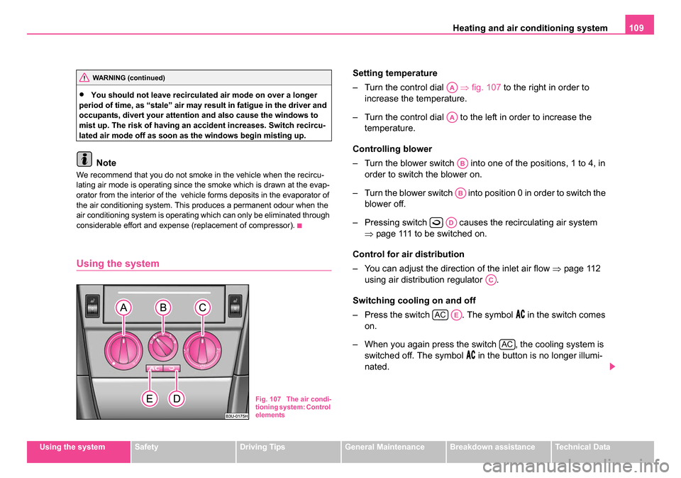
– Turn the control dial ⇒fig. 107 to the right in order to
increase the temperature.
– Turn the control dial to the left in order to increase the temperature.
Controlling blower
– Turn the blower switch into one of the positions, 1 to 4, in order to switch the blower on.
– Turn the blower switch into position 0 in order to switch the blower off.
– Pressing switch causes the recirculating air system ⇒page 111 to be switched on.
Control for air distribution
– You can adjust the direction of the inlet air flow ⇒page 112
using air distribution regulator .
Switching cooling on and off
– Press the switch . The symbol
in the switch comes
on.
– When you again press the switch , the cooling system is switched off. The symbol
in the button is no longer illumi-
nated.
WARNING (continued)
Fig. 107 The air condi-
tioning system: Control
elements
AA
AA
AB
AB
AD
AC
ACAE
AC
NKO B5 20.book Page 109 Monday, July 3, 2006 2:09 PM