fuel cap SKODA SUPERB 2006 1.G / (B5/3U) Owner's Manual
[x] Cancel search | Manufacturer: SKODA, Model Year: 2006, Model line: SUPERB, Model: SKODA SUPERB 2006 1.G / (B5/3U)Pages: 281, PDF Size: 12.67 MB
Page 16 of 281
Instruments and Indicator/Warning Lights15
Using the systemSafetyDriving TipsGeneral MaintenanceBreakdown assistanceTechnical Data
Fuel gauge
The fuel gauge âpage 13, fig. 2 only operates when the ignition is
switched on.
The fuel tank has a capacity of about 62 litres. The warning symbol
ï in
the instrument cluster lights up when the pointer reaches the reserve
marking. There are now about 8 litres of fuel remaining in the tank. This
symbol is a reminder for you, that you must refuel.
The following will be displayed in the information display*:
PLEASE REFUEL
A peep sounds as an additional warning signal.
Caution
Never run the fuel tank completely empty! An irregular fuel supply can
result in poor ignition or misfiring. Unburnt fuel may get into the exhaust
system and damage the catalytic converter.
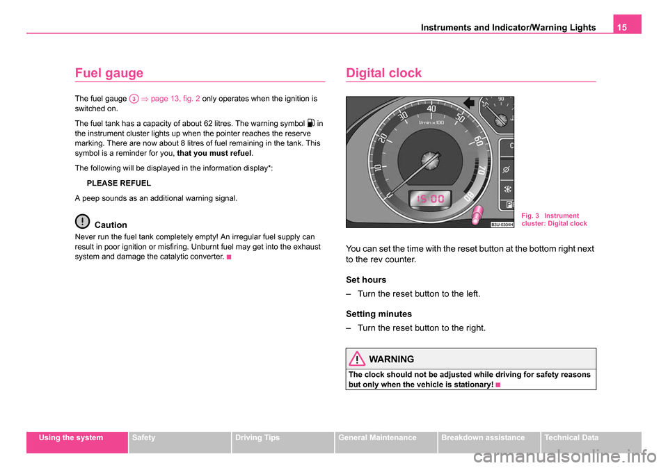
Digital clock
You can set the time with the reset button at the bottom right next
to the rev counter.
Set hours
â Turn the reset button to the left.
Setting minutes
â Turn the reset button to the right.
WARNING
The clock should not be adjusted while driving for safety reasons
but only when the vehicle is stationary!
A3
Fig. 3 Instrument
cluster: Digital clock
NKO B5 20.book Page 15 Monday, July 3, 2006 2:09 PM
Page 33 of 281
Instruments and Indicator/Warning Lights
32
Coolant temperature, Coolant quantity ï¯
The warning light ï¯ comes on for a few seconds 1) when the ignition is
switched on.
The coolant temperature is too high or the coolant level too low if the
warning light
ï¯ does not go out after the engine is started or flashes while
driving.
3 peeps sound as an additional warning signal.
In this case stop and switch the engine off and check the coolant level;
top up the coolant as necessary. Please also refer to the additional
instructions âpage 226, âReplenishing the coolantâ.
Do not continue your journey if for some reason it is not possible under
the conditions prevailing to top up with coolant. Keep the engine
switched off and obtain professional assistance from a specialist garage,
otherwise it could lead to severe engine damage.
If the coolant is within the specified range, the increased temperature may
be caused by an operating problem at the coolant fan. Check the fuse for
the coolant fan, replace it if necessary âpage 260, âReplacing fusesâ.
Do not continue driving if the warning light does not go off although the
fluid is at the correct level and also the fuse of the fan is in proper order.
Contact a specialist garage to obtain assistance.
Please also refer to the additional instructions âpage 226, âReplenishing
the coolantâ.
The following text will be displayed in the information display*:
STOP CHECK COOLANT SERVICE MANUAL (STOP! CHECK
COOLANT! OWNER'S MANUAL)
WARNING
â¢If you must stop for technical reasons, then park the vehicle at
a safe distance from the traffic and switch off the engine and switch
on the hazard warning light system âpage 59.
â¢Take care when opening the coolant expansion bottle. If the
engine is hot, the cooling system is pressurized - risk of scalding!
It is best to allow the engine to cool down before removing the cap.
â¢Do not touch the coolant fan! The coolant fan may switch on
automatically even if the ignition is off.
Thickness of the brake pads ï©
If the warning light ï© comes on, contact a specialist garage immediately
and have the brake pads on all of the wheels inspected.
A peep sounds as an additional warning signal.
The following text will be displayed in the information display*:
CHECK BRAKE PADS
Bonnet ï±
The warning light ï± comes on when the ignition is switched on if the
bonnet is unlocked.
Fuel reserve ï
The warning light ï comes on, if the fuel level is still below 8 litres.
1)The warning light ï¯ on vehicles fitted with information display does not come on
after switching the ignition on, but only if the coolant temperature is too high or the
coolant level is too low.
NKO B5 20.book Page 32 Monday, July 3, 2006 2:09 PM
Page 113 of 281
Heating and air conditioning system
112
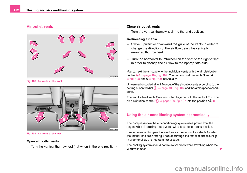
Air outlet vents
Fig. 108 Air vents at the front
Fig. 109 Air vents at the rear
Open air outlet vents
â Turn the vertical thumbwheel (not when in the end position). Close air outlet vents
â Turn the vertical thumbwheel into the end position.
Redirecting air flow
â Swivel upward or downward the gr
ille of the vents in order to
change the direction of the air flow using the vertically
arranged thumbwheel.
â Turn the horizontal thumbwheel on the vent to the right or left in order to change the air flow to the appropriate side.
You can set the air supply to the individual vents with the air distribution
control âpage 109, fig. 107 . You can also set the vents 3 and 4
â fig. 108 and 6 â fig. 109 individually.
Unwarmed or cooled air will flow out of the air outlet vents according to the
setting of control dial âpage 109, fig. 107 and the atmospheric condi-
tions.
The rear footwell vents 7 are controlled together with the vents 5. Turn the
air distribution control âpage 109, fig. 107 into the position
ïª.
Using the air conditioning system economically
The compressor on the air conditioning system uses power from the
engine when in cooling mode which will effect the fuel consumption.
It recommended to open the windows or the doors of a vehicle for which
the interior has been strongly heated through the effect of direct sunlight
in order to allow the heated air to escape.
The cooling system should not be switched on while travelling when the
window is open.
AC
AA
AC
NKO B5 20.book Page 112 Monday, July 3, 2006 2:09 PM
Page 114 of 281
Heating and air conditioning system 113
Using the systemSafetyDriving TipsGeneral MaintenanceBreakdown assistanceTechnical Data
The desired interior temperature can also be achieved without switching
in the cooling system just by switching to fresh air mode.
For the sake of
the environment
When you economize on fuel, you also reduce pollutant emissions.
Operational problems
If the cooling system does not operate at outside temperatures higher
than +5 °C, there is a problem in the system. The reasons for this may be:
â¢The fuse of the air conditioning system is defective âpage 260.
Check the fuse, replace it if necessary.
â¢The cooling system has switched off automatically for a short time
because the coolant temperature of the engine is too hot.
If you are not able to rectify the operational problem yourself, or if the
cooling capacity decreases, switch the cooling system off. Contact a
specialist garage.
Climatronic* (automatic air conditioning)
Description
The Climatronic system is a combination of an automatic heating, fresh air
and cooling system which provides optimal comfort for the occupants of
the car.
The Climatronic maintains a constant temperature fully automatically,
once it has been set. This is achieved by automatically varying the temperature of the outflowing air, the blower stages and the air distribu-
tion. It is not necessary to manually alter the settings. The
automatic
mode â page 115 ensures maximum wellbeing of the occupants at all
times of the year.
Description of Climatronic system
The Climatronic can only operate if the following conditions are met:
â¢engine running,
â¢outside temperature above +5 °C,
â¢the button is not pressed.
If the Climatronic system is switched on, the temperature and air humidity
drops in the vehicle. The wellbeing of the occupants of the car is enhanced
as a result of this particularly at high outside temperatures and a high air
humidity. The system prevents the windows misting up during the cold
season of the year.
It is possible to briefly activate recirculated air mode in order to enhance
the cooling effect â.
The heating effect is dependent upon the coolant temperature, thus full
heat output only occurs when the engine has reached its operating
temperature.
Puddle of water below car
After switching on the cooling Condensation from the evaporator of the
air conditioning may drip down and form a puddle below the vehicle. This
is quite normal and not an indication of a leak!
Switching over between degrees Celsius and degrees Fahrenheit
First of all press and hold the button âpage 114, fig. 110 and then
press the button . The temperature measuring unit appears in the
display.ECON
ECONAUTO
NKO B5 20.book Page 113 Monday, July 3, 2006 2:09 PM
Page 217 of 281
Fuel
216
It is therefore the case that DIN EN 590 prescribes diesel fuel class for
certain periods of the year which can also be purchased at the corre-
sponding time during the year. âWinter-grade diesel fuelâ will still operate
properly even at a temperature of -20°C.
It is often the case in countries with different climatic conditions that diesel
fuels available have a different temperature characteristic. Å koda Service
Partners and filling stations in the country concerned will be able to
provide you with information regarding the diesel fuels available.
Prewarming fuel
The vehicle is fitted with a fuel filter prewarming system. This secures
operation of a vehicle using diesel fuel down to an environmental temper-
ature of -25°C.
Biofuel
We recommend refuelling with diesel fuel at temperatures below -10°C.
Caution
It is not permitted to add the various fuel additives on the market, including
petrol, to diesel fuel in order to improve its flow properties.
Refuelling
Refuelling procedure
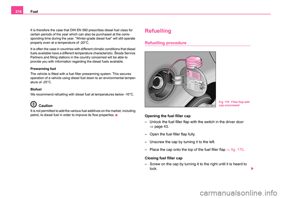
Opening the fuel filler cap
â Unlock the fuel filler flap with the switch in the driver door
âpage 43.
â Open the fuel filler flap fully.
â Unscrew the cap by turning it to the left.
â Place the cap onto the top of the fuel filler flap âfig. 170 .
Closing fuel filler cap
â Screw on the cap by turning it to the right until it is heard to lock.
Fig. 170 Filler flap with
cap unscrewed
NKO B5 20.book Page 216 Monday, July 3, 2006 2:09 PM
Page 218 of 281
Fuel217
Using the systemSafetyDriving TipsGeneral MaintenanceBreakdown assistanceTechnical Data
â Press the fuel tank flap closed.
The correct grade of fuel for your vehicle as well as the tyre size and infla-
tion pressures are stated on a sticker affixed to the inside of the fuel filler
flap. Further information on fuel âpage 214, âFuelâ.
The fuel tank has a capacity of about 62 litres.
WARNING
Pay attention to any legal requirements if you do carry a spare
canister in the vehicle. We do not recommend carrying any fuel
canisters in your vehicle for safety reasons. The canister can be
damaged in the event of an accident and fuel may leak out.
Caution
â¢Remove any fuel which has spilled onto the paintwork of your vehicle
immediately. This particularly applies to biodiesel - risk of paint damage!
â¢Vehicles fitted with catalytic converter should never be allowed to let
the fuel tank to run completely empty. An irregular supply of fuel to the
engine can result in misfiring and unburnt fuel may get into the exhaust
system, which may result in overheating and damage to the catalytic
converter.
For the sake of the environment
The fuel tank is full just as soon as the pump nozzle switches off for the
first time, provided the nozzle has been operated properly. You should not
continue refuelling - otherwise the expansion chamber in the fuel tank will
also be filled with fuel. Fuel might flow out of the tank when it heats up.
Emergency release of fuel filler flap
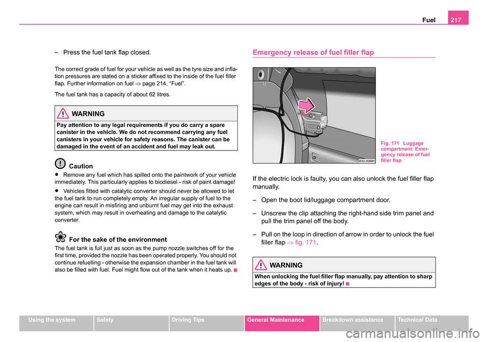
If the electric lock is faulty, you can also unlock the fuel filler flap
manually.
â Open the boot lid/luggage compartment door.
â Unscrew the clip attaching the right-hand side trim panel and
pull the trim panel off the body.
â Pull on the loop in direction of arrow in order to unlock the fuel filler flap âfig. 171 .
WARNING
When unlocking the fuel filler flap manually, pay attention to sharp
edges of the body - risk of injury!
Fig. 171 Luggage
compartment: Emer-
gency release of fuel
filler flap
NKO B5 20.book Page 217 Monday, July 3, 2006 2:09 PM
Page 236 of 281

Wheels and Tyres235
Using the systemSafetyDriving TipsGeneral MaintenanceBreakdown assistanceTechnical Data
Wheels and Tyres
Wheels
General comments
â¢New tyres do not offer optimal grip at first and should therefore be run
in for about 500 km at a moderate speed and an appropriately cautious
style of driving. You will also profit from longer tyre life.
â¢The tread depth of new tyres may differ because of design features
and the configuration of the tread (depending on the type of tyre and the
manufacturer).
â¢Drive over curbs on the side of the road and other such obstacles
slowly and, where possible, at a right angles in order to avoid damage to
tyres and wheel trims.
â¢Inspect your tyres from time to time for damage (punctures, cuts, splits
and bulges). Remove foreign bodies from the tyre profile.
â¢Damage to tyres and wheels is frequently not visible. Unusual vibra-
tions or pulling of the vehicle to one side could be a sign of tyre damage.
Please reduce your speed immediately and stop if you suspect that
a wheel is damaged. Inspect the tyres for signs of damage (bulges,
splits, etc.) If no visible damage is present, please drive at an appropri-
ately slow speed and carefully to the nearest specialist garage in order to
have your vehicle inspected.
â¢Also protect your tyres from contact with oil, grease and fuel.
â¢Immediately replace any dust caps of the valves which have got lost.
â¢Mark wheels before removing them so that their previous direction of
running can be maintained when mounted them again.
â¢Always store wheels or tyres which been removed in a cool, dry and,
where possible, dark place. Tyres which are not fixed to a wheel trim
should be stored upright. Unidirectional tyres*
The direction of rotation of the tyres is marked by arrows on the wall of the
tyre. This indicates the direction of rotation of the tyre, and it is essential
that the tyres are fitted on to run in this direction. Only then are the tyres
able to provide the optimal properties in terms of grip, low noise, wear-
and-tear and aquaplaning.
Further information concerning the use of unidirectional tyres
â
page 241.
WARNING
â¢New tyres during the first 500 km do not offer optimal grip and
should therefore be run approp riately - risk of accident!
â¢Never drive with damaged tyres - risk of accident!
Note
Please observe the various differing legal requirements regarding tyres.
NKO B5 20.book Page 235 Monday, July 3, 2006 2:09 PM
Page 237 of 281
Wheels and Tyres
236
Tyre life
The life of your tyres very much depends on the following points: Tyre pressure
The working life of tyres will be shortened considerably if the tyres are
insufficiently or over-inflated and this will have an adverse effect on the
handling of your vehicle.
Correctly inflated tyres are of particular importance when travelling at
high
speeds . It is therefore good to check the pressure at least once a month
and also before setting off on a long trip. Please do not forget the spare
wheel when checking the tyres.
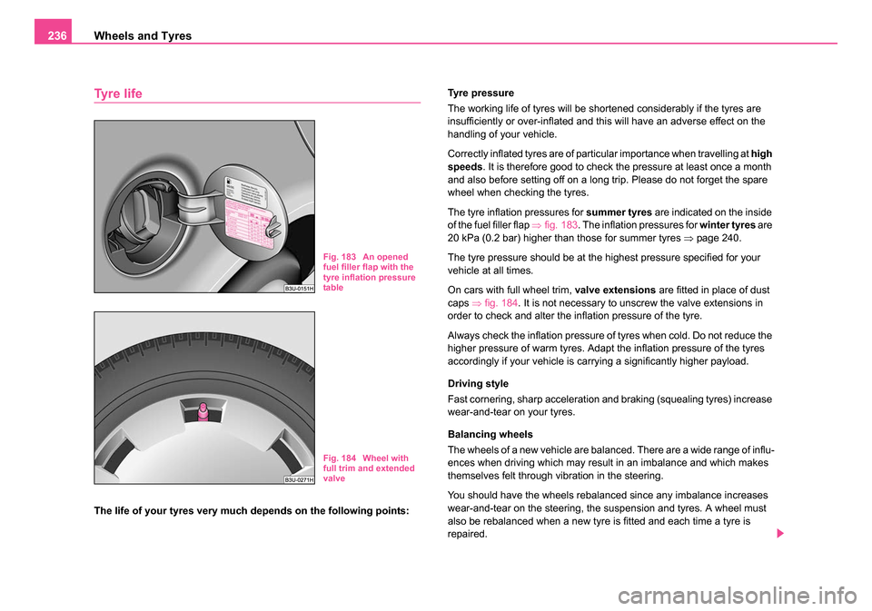
The tyre inflation pressures for summer tyres are indicated on the inside
of the fuel filler flap âfig. 183 . The inflation pressures for winter tyres are
20 kPa (0.2 bar) higher than those for summer tyres âpage 240.
The tyre pressure should be at the highest pressure specified for your
vehicle at all times.
On cars with full wheel trim, valve extensions are fitted in place of dust
caps âfig. 184 . It is not necessary to unscrew the valve extensions in
order to check and alter the inflation pressure of the tyre.
Always check the inflation pressure of tyres when cold. Do not reduce the
higher pressure of warm tyres. Adapt the inflation pressure of the tyres
accordingly if your vehicle is carrying a significantly higher payload.
Driving style
Fast cornering, sharp acceleration and braking (squealing tyres) increase
wear-and-tear on your tyres.
Balancing wheels
The wheels of a new vehicle are balanced. There are a wide range of influ-
ences when driving which may result in an imbalance and which makes
themselves felt through vibration in the steering.
You should have the wheels rebalanced since any imbalance increases
wear-and-tear on the steering, the suspension and tyres. A wheel must
also be rebalanced when a new tyre is fitted and each time a tyre is
repaired.
Fig. 183 An opened
fuel filler flap with the
tyre inflation pressure
table
Fig. 184 Wheel with
full trim and extended
valve
NKO B5 20.book Page 236 Monday, July 3, 2006 2:09 PM