fuse SKODA SUPERB 2006 1.G / (B5/3U) Owner's Manual
[x] Cancel search | Manufacturer: SKODA, Model Year: 2006, Model line: SUPERB, Model: SKODA SUPERB 2006 1.G / (B5/3U)Pages: 281, PDF Size: 12.67 MB
Page 7 of 281
Contents
6
Transporting children safely. . . . . . . . . . . . .
What you should know about transporting
children! . . . . . . . . . . . . . . . . . . . . . . . . . . . . .
Child seat . . . . . . . . . . . . . . . . . . . . . . . . . . . .
Attaching child safety seat . . . . . . . . . . . . . . .
Driving Tips . . . . . . . . . . . . . . . . . . . . . .
Intelligent Technology . . . . . . . . . . . . . . . . . .
Electronic stability programme (ESP)* . . . . . .
Brakes . . . . . . . . . . . . . . . . . . . . . . . . . . . . . .
Brake booster . . . . . . . . . . . . . . . . . . . . . . . .
Antilock brake system (ABS) . . . . . . . . . . . . .
Brake Assist* . . . . . . . . . . . . . . . . . . . . . . . . .
Power steering . . . . . . . . . . . . . . . . . . . . . . . .
Driving and the Environment. . . . . . . . . . . .
The first 1 500 kilometres and then afterwards
Catalytic converter . . . . . . . . . . . . . . . . . . . . .
Driving in an economical and environmentally
conscious manner . . . . . . . . . . . . . . . . . . . . .
Environmental compatibility . . . . . . . . . . . . . .
Motoring abroad . . . . . . . . . . . . . . . . . . . . . . .
Avoiding damage to your vehicle . . . . . . . . . .
Towing a trailer . . . . . . . . . . . . . . . . . . . . . . . .
Towing a trailer . . . . . . . . . . . . . . . . . . . . . . . .
Detachable towing device* . . . . . . . . . . . . . .
General Maintenance . . . . . . . . . .
Taking care of your vehicle and cleaning the
vehicle. . . . . . . . . . . . . . . . . . . . . . . . . . . . . . . .
General . . . . . . . . . . . . . . . . . . . . . . . . . . . . .
Care of the exterior of vehicle . . . . . . . . . . . .
Care of the interior of vehicle . . . . . . . . . . . . .
Fuel. . . . . . . . . . . . . . . . . . . . . . . . . . . . . . . . . .
Petrol . . . . . . . . . . . . . . . . . . . . . . . . . . . . . . .
Diesel . . . . . . . . . . . . . . . . . . . . . . . . . . . . . .
Refuelling . . . . . . . . . . . . . . . . . . . . . . . . . . .
Inspecting and Replenishing. . . . . . . . . . . .
Engine compartment . . . . . . . . . . . . . . . . . . .
Overview of the engine compartment . . . . . .
Engine oil . . . . . . . . . . . . . . . . . . . . . . . . . . . .
Cooling system . . . . . . . . . . . . . . . . . . . . . . .
Brake fluid . . . . . . . . . . . . . . . . . . . . . . . . . . .
Battery . . . . . . . . . . . . . . . . . . . . . . . . . . . . . .
Windshield washer system . . . . . . . . . . . . . .
Wheels and Tyres . . . . . . . . . . . . . . . . . . . . .
Wheels . . . . . . . . . . . . . . . . . . . . . . . . . . . . .
Accessories, changes and replacement of
parts . . . . . . . . . . . . . . . . . . . . . . . . . . . . . . . . .
Accessories and replacement parts . . . . . . .
Technical changes . . . . . . . . . . . . . . . . . . . . .
Breakdown assistance . . . . . . . .
Breakdown assistance . . . . . . . . . . . . . . . . .
First-aid box* . . . . . . . . . . . . . . . . . . . . . . . . .
Warning triangle . . . . . . . . . . . . . . . . . . . . . .
Fire extinguisher* . . . . . . . . . . . . . . . . . . . . . .
Vehicle tool kit . . . . . . . . . . . . . . . . . . . . . . . .
Spare wheel . . . . . . . . . . . . . . . . . . . . . . . . . .
Changing a wheel . . . . . . . . . . . . . . . . . . . . .
Jump-starting . . . . . . . . . . . . . . . . . . . . . . . . .
Tow-starting and towing vehicle . . . . . . . . . . .
Fuses and light bulbs . . . . . . . . . . . . . . . . . .
Electric fuses . . . . . . . . . . . . . . . . . . . . . . . . .
Bulbs . . . . . . . . . . . . . . . . . . . . . . . . . . . . . . .
Te c h n i c a l D a ta . . . . . . . . . . . . . . . . . .
General . . . . . . . . . . . . . . . . . . . . . . . . . . . . . .
Identification data . . . . . . . . . . . . . . . . . . . . .
Index . . . . . . . . . . . . . . . . . . . . . . . . . . . . . .
174
174
178
181
185
185
185
188
189
189
190
191
192
192
193
194
198
199
199
200
200
202
205
205
205
205
211 214
214
214
216
218
218
220
221
224
227
228
233
235
235
242
242
242
245
245
245
245
246
246
247
248
255
257
260
260
262
269
269
269
271
NKO B5 20.book Page 6 Monday, July 3, 2006 2:09 PM
Page 12 of 281
Cockpit11
Using the systemSafetyDriving TipsGeneral MaintenanceBreakdown assistanceTechnical Data
Cockpit
General view
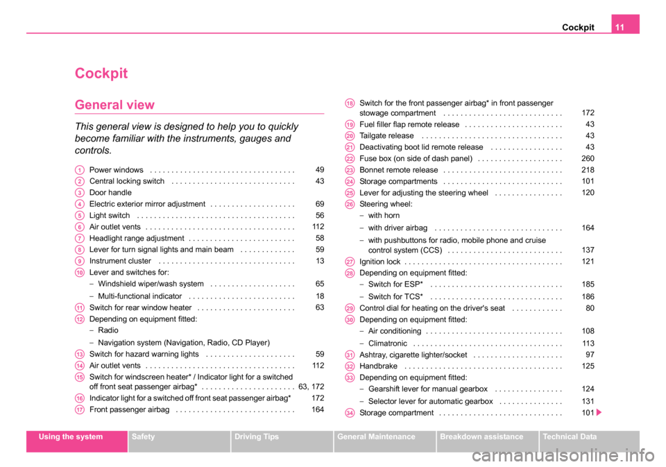
This general view is designed to help you to quickly
become familiar with the instruments, gauges and
controls.
Power windows . . . . . . . . . . . . . . . . . . . . . . . . . . . . . . . . . .
Central locking switch . . . . . . . . . . . . . . . . . . . . . . . . . . . . .
Door handle
Electric exterior mirror adjustment . . . . . . . . . . . . . . . . . . . .
Light switch . . . . . . . . . . . . . . . . . . . . . . . . . . . . . . . . . . . . .
Air outlet vents . . . . . . . . . . . . . . . . . . . . . . . . . . . . . . . . . . .
Headlight range adjustment . . . . . . . . . . . . . . . . . . . . . . . . .
Lever for turn signal lights and main beam . . . . . . . . . . . . .
Instrument cluster . . . . . . . . . . . . . . . . . . . . . . . . . . . . . . . .
Lever and switches for:
−Windshield wiper/wash system . . . . . . . . . . . . . . . . . . . .
− Multi-functional indicator . . . . . . . . . . . . . . . . . . . . . . . . .
Switch for rear window heater . . . . . . . . . . . . . . . . . . . . . . .
Depending on equipment fitted:
− Radio
− Navigation system (Navigation, Radio, CD Player)
Switch for hazard warning lights . . . . . . . . . . . . . . . . . . . . .
Air outlet vents . . . . . . . . . . . . . . . . . . . . . . . . . . . . . . . . . . .
Switch for windscreen heater* / Indicator light for a switched
off front seat passenger airbag* . . . . . . . . . . . . . . . . . . . . . .
Indicator light for a switched off front seat passenger airbag*
Front passenger airbag . . . . . . . . . . . . . . . . . . . . . . . . . . . . Switch for the front passenger airbag* in front passenger
stowage compartment . . . . . . . . . . . . . . . . . . . . . . . . . . . .
Fuel filler flap remote release . . . . . . . . . . . . . . . . . . . . . . .
Tailgate release . . . . . . . . . . . . . . . . . . . . . . . . . . . . . . . . .
Deactivating boot lid remote release . . . . . . . . . . . . . . . . .
Fuse box (on side of dash panel) . . . . . . . . . . . . . . . . . . . .
Bonnet remote release . . . . . . . . . . . . . . . . . . . . . . . . . . . .
Storage compartments . . . . . . . . . . . . . . . . . . . . . . . . . . . .
Lever for adjusting the steering wheel . . . . . . . . . . . . . . . .
Steering wheel:
−
with horn
− with driver airbag . . . . . . . . . . . . . . . . . . . . . . . . . . . . . .
− with pushbuttons for radio, mobile phone and cruise
control system (CCS) . . . . . . . . . . . . . . . . . . . . . . . . . . .
Ignition lock . . . . . . . . . . . . . . . . . . . . . . . . . . . . . . . . . . . . .
Depending on equipment fitted:
− Switch for ESP* . . . . . . . . . . . . . . . . . . . . . . . . . . . . . . .
− Switch for TCS* . . . . . . . . . . . . . . . . . . . . . . . . . . . . . . .
Control dial for heating on the driver's seat . . . . . . . . . . . .
Depending on equipment fitted:
− Air conditioning . . . . . . . . . . . . . . . . . . . . . . . . . . . . . . . .
− Climatronic . . . . . . . . . . . . . . . . . . . . . . . . . . . . . . . . . . .
Ashtray, cigarette lighter/socket . . . . . . . . . . . . . . . . . . . . .
Handbrake . . . . . . . . . . . . . . . . . . . . . . . . . . . . . . . . . . . . .
Depending on equipment fitted:
− Gearshift lever for manual gearbox . . . . . . . . . . . . . . . .
− Selector lever for automatic gearbox . . . . . . . . . . . . . . .
Storage compartment . . . . . . . . . . . . . . . . . . . . . . . . . . . . . A149
A243
A3
A469
A556
A611 2
A758
A859
A913
A10
65
18
A1163
A12
A1359
A1411 2
A1563, 172
A16172
A17164
A18172
A1943
A2043
A2143
A22260
A23218
A24101
A25120
A26
164
137
A27121
A28
185
186
A2980
A30
108
11 3
A3197
A32125
A33
124
131
A34101
NKO B5 20.book Page 11 Monday, July 3, 2006 2:09 PM
Page 33 of 281
Instruments and Indicator/Warning Lights
32
Coolant temperature, Coolant quantity
The warning light comes on for a few seconds 1) when the ignition is
switched on.
The coolant temperature is too high or the coolant level too low if the
warning light
does not go out after the engine is started or flashes while
driving.
3 peeps sound as an additional warning signal.
In this case stop and switch the engine off and check the coolant level;
top up the coolant as necessary. Please also refer to the additional
instructions ⇒page 226, “Replenishing the coolant”.
Do not continue your journey if for some reason it is not possible under
the conditions prevailing to top up with coolant. Keep the engine
switched off and obtain professional assistance from a specialist garage,
otherwise it could lead to severe engine damage.
If the coolant is within the specified range, the increased temperature may
be caused by an operating problem at the coolant fan. Check the fuse for
the coolant fan, replace it if necessary ⇒page 260, “Replacing fuses”.
Do not continue driving if the warning light does not go off although the
fluid is at the correct level and also the fuse of the fan is in proper order.
Contact a specialist garage to obtain assistance.
Please also refer to the additional instructions ⇒page 226, “Replenishing
the coolant”.
The following text will be displayed in the information display*:
STOP CHECK COOLANT SERVICE MANUAL (STOP! CHECK
COOLANT! OWNER'S MANUAL)
WARNING
•If you must stop for technical reasons, then park the vehicle at
a safe distance from the traffic and switch off the engine and switch
on the hazard warning light system ⇒page 59.
•Take care when opening the coolant expansion bottle. If the
engine is hot, the cooling system is pressurized - risk of scalding!
It is best to allow the engine to cool down before removing the cap.
•Do not touch the coolant fan! The coolant fan may switch on
automatically even if the ignition is off.
Thickness of the brake pads
If the warning light comes on, contact a specialist garage immediately
and have the brake pads on all of the wheels inspected.
A peep sounds as an additional warning signal.
The following text will be displayed in the information display*:
CHECK BRAKE PADS
Bonnet
The warning light comes on when the ignition is switched on if the
bonnet is unlocked.
Fuel reserve
The warning light comes on, if the fuel level is still below 8 litres.
1)The warning light on vehicles fitted with information display does not come on
after switching the ignition on, but only if the coolant temperature is too high or the
coolant level is too low.
NKO B5 20.book Page 32 Monday, July 3, 2006 2:09 PM
Page 95 of 281

Seats and Stowage
94
– Close the lid in direction of arrow 2.
– Press on the button marked “PUSH” ⇒page 93, fig. 84
and push the folding box into the secured middle position.
– Once again press on the button marked “PUSH” and push the folding box carefully into the secured position against the
partition of the luggage compartment in direction of arrow 3
(ready position). If correctly locked, the button marked “PUSH” is moved back into its initial position.
You can leave the folding box in the ready position for use, or fold it down
into the transport position ⇒page 91.
Caution
•The parts of the folding box can be damaged if handled roughly or in
an unprofessional way.
•First check for yourself whether the cover for the through-loading bag*
is closed before you lower the folding box into the ready position on the
partition of the luggage compartment ⇒page 87.
The roof luggage rack system
Description
Pay attention to the following points if you wish to transport luggage or
other items on the roof of your vehicle:
•Your car has streamlined rain channels integrated into the roof. For
this reason, it is not possible to use conventional roof racks. We therefore recommend that you only use base roof bars from the Škoda Genuine
Accessories.
•These base roof bars are the supporting elements for a complete roof
bar system. Separate additional components are required for safety
reasons for transporting luggage, bikes, surfboards, skis and boats. All
these components you can obtain replacement fuses from a Škoda
Service Partner.
Caution
•If you use other roof rack systems or if the roof bars are not properly
fitted, then any damage which may result to your car is not covered by the
warranty agreements. It is therefore essential to pay attention to the fitting
instructions supplied with the roof luggage rack system.
•On models fitted with a power sliding/tilting roof, ensure that the
opened sliding/tilting roof does not strike any items of luggage transported
on the roof.
For the sake of the environment
The increased aerodynamic drag results in a higher fuel consumption.
One should therefore take off the roof bar system after use.
AB
AB
AB
NKO B5 20.book Page 94 Monday, July 3, 2006 2:09 PM
Page 114 of 281
Heating and air conditioning system 113
Using the systemSafetyDriving TipsGeneral MaintenanceBreakdown assistanceTechnical Data
The desired interior temperature can also be achieved without switching
in the cooling system just by switching to fresh air mode.
For the sake of
the environment
When you economize on fuel, you also reduce pollutant emissions.
Operational problems
If the cooling system does not operate at outside temperatures higher
than +5 °C, there is a problem in the system. The reasons for this may be:
•The fuse of the air conditioning system is defective ⇒page 260.
Check the fuse, replace it if necessary.
•The cooling system has switched off automatically for a short time
because the coolant temperature of the engine is too hot.
If you are not able to rectify the operational problem yourself, or if the
cooling capacity decreases, switch the cooling system off. Contact a
specialist garage.
Climatronic* (automatic air conditioning)
Description
The Climatronic system is a combination of an automatic heating, fresh air
and cooling system which provides optimal comfort for the occupants of
the car.
The Climatronic maintains a constant temperature fully automatically,
once it has been set. This is achieved by automatically varying the temperature of the outflowing air, the blower stages and the air distribu-
tion. It is not necessary to manually alter the settings. The
automatic
mode ⇒ page 115 ensures maximum wellbeing of the occupants at all
times of the year.
Description of Climatronic system
The Climatronic can only operate if the following conditions are met:
•engine running,
•outside temperature above +5 °C,
•the button is not pressed.
If the Climatronic system is switched on, the temperature and air humidity
drops in the vehicle. The wellbeing of the occupants of the car is enhanced
as a result of this particularly at high outside temperatures and a high air
humidity. The system prevents the windows misting up during the cold
season of the year.
It is possible to briefly activate recirculated air mode in order to enhance
the cooling effect ⇒.
The heating effect is dependent upon the coolant temperature, thus full
heat output only occurs when the engine has reached its operating
temperature.
Puddle of water below car
After switching on the cooling Condensation from the evaporator of the
air conditioning may drip down and form a puddle below the vehicle. This
is quite normal and not an indication of a leak!
Switching over between degrees Celsius and degrees Fahrenheit
First of all press and hold the button ⇒page 114, fig. 110 and then
press the button . The temperature measuring unit appears in the
display.ECON
ECONAUTO
NKO B5 20.book Page 113 Monday, July 3, 2006 2:09 PM
Page 124 of 281

Starting-off and Driving123
Using the systemSafetyDriving TipsGeneral MaintenanceBreakdown assistanceTechnical Data
For the sake of the environment
Never warm up the engine when the vehicle is standing. Drive off right
away. Through this the engine reaches its operating temperature more
rapidly and the pollutant emissions are lower.
Petrol engines
These engines are fitted with a starter system which selects the correct
fuel/air mixture for every external air temperature.
•Do not operate accelerator before and when starting engine.
•Interrupt the attempt at starting after 10 seconds if the engine does not
start right awayand wait for about 30 seconds before repeating the
attempt.
•It is possible that the fuse on the electrical fuel pump is defect if the
engine still does not start. Check the fuse and replace it if necessary
⇒ page 260.
•If the engine does not start, contact the nearest specialist garage to
obtain professional assistance.
It may be necessary, if the engine is very hot, to slightly depress the
accelerator after the engine has started.
Diesel engines
Glow plug system
Diesel engines are equipped with a glow plug system, the preglow period
being controlled automatically in line with the coolant temperature and
outside temperature. The preglow indicator light
comes on after the ignition has been
switched on.
You should not switch on any major electrical components during
the heating period otherwise the vehicle battery will be drained
unnecessarily.
•You should start the engine immediately after the glow plug warning
light has gone out.
•The glow plug warning light will come on for about one second if the
engine is at a normal operating temperature or if the outside temperature
is above +5°C. This means that you can start the engine right away.
•Interrupt the attempt at starting after 10 seconds if the engine does not
start right awayand wait for about 30 seconds before repeating the
attempt.
•It is possible that the fuse on the diesel preglow system is defect if the
engine still does not start. Check the fuse and replace it if necessary
⇒ page 260.
•If the engine does not start, contact the nearest specialist garage to
obtain professional assistance.
Starting the engine after fuel tank has run dry
It may take longer than normal to start the engine after refuelling if the fuel
tank has run completely dry - up to one minute. This is because the fuel
system must first of all be filled while the attempting to start the engine.
Switching the engine off
– Turn the ignition key into position ⇒page 121, fig. 115 .A1
NKO B5 20.book Page 123 Monday, July 3, 2006 2:09 PM
Page 140 of 281

Communicating and Navigating139
Using the systemSafetyDriving TipsGeneral MaintenanceBreakdown assistanceTechnical Data
Operating mobile phone
– You can operate the mobile phone with buttons , and
⇒fig. 128 .
– You can switch over from the radio mode to the phone mode (or back again) by pressing the button in the position
MODE .
– You can accept or end a telephone call or select from the phonebook by briefly pressing the button in the position
.
– You can refuse a telephone call by pressing the button in the position
for more than 2 seconds.
– You can make the volume of the telephone call louder or softer by pressing the button in the position
or
– You call scroll through the telephone memory for names by briefly pressing the button in the position
or . – You can scroll alphabetically upwa
rd (A to Z) or downward (Z
to A) within the telephone memory by pressing for some
considerable time the button in the position
and .
If you switch over with the button MODE on the multifunction steering
wheel ⇒fig. 128 to phone mode and the mobile phone is not in the
adapter, INSERT PHONE appears in the display. After inserting the
mobile phone, PHONE IN appears on the display.
Afterwards PHONE STARTUP appears on the display and the system
transmits the data from the mobile phone to the information display. The
following is shown one after the other on the display:
•DIALED CALLS LOADING: xxx
•RCVD CALLS LOADING: xxx
•MISSED CALLS LOADING: xxx
•PHONEBOOK LOADING
One cannot scroll through the phonebook during data transfer out of the
mobile phone. After the data transfer has ended, the first name out of the
phonebook is shown on the display
You can scroll through the individual menus by pressing the button in
the position
or ⇒ fig. 128 .
Select the entry you want by pressing the button in the position
.
You will reach one level higher in the menu by pressing the button in
the position MODE.
In the main menu you can select the following entries:
•PHONEBOOK
•SETUP
•LAST CALLS
•RECEIVED CALLS
•MISSED CALLS
Fig. 128 Multifunction
steering wheel: control
buttons
A2A3A4
A2
A2
A2
A3
A4
A4
A4
A2
A2
NKO B5 20.book Page 139 Monday, July 3, 2006 2:09 PM
Page 261 of 281
Fuses and light bulbs
260
Fuses and light bulbs
Electric fuses
Replacing fuses
Defect fuses must be replaced.
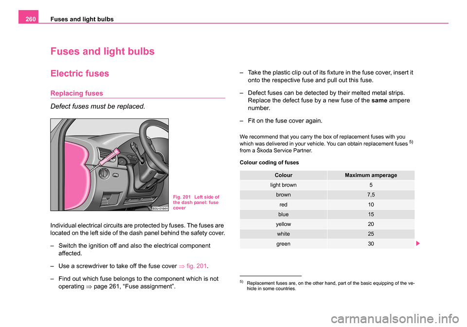
Individual electrical circuits are protected by fuses. The fuses are
located on the left side of the dash panel behind the safety cover.
– Switch the ignition off and also the electrical component
affected.
– Use a screwdriver to take off the fuse cover ⇒fig. 201.
– Find out which fuse belongs to the component which is not operating ⇒page 261, “Fuse assignment”. – Take the plastic clip out of its fixture in the fuse cover, insert it
onto the respective fuse and pull out this fuse.
– Defect fuses can be detected by their melted metal strips. Replace the defect fuse by a new fuse of the same ampere
number.
– Fit on the fuse cover again.
We recommend that you carry the box of replacement fuses with you
which was delivered in your vehicle. You can obtain replacement fuses 5)
from a Škoda Service Partner.
Colour coding of fuses
Fig. 201 Left side of
the dash panel: fuse
cover
5)Replacement fuses are, on the other hand, part of the basic equipping of the ve-
hicle in some countries.
ColourMaximum amperage
light brown5
brown7,5
red10
blue15
yellow20
white25
green30
NKO B5 20.book Page 260 Monday, July 3, 2006 2:09 PM
Page 262 of 281
Fuses and light bulbs261
Using the systemSafetyDriving TipsGeneral MaintenanceBreakdown assistanceTechnical Data
Caution
•Never attempt to “repair” fuses and also do not replace them with a
fuse of a higher amperage - risk of fire! This may also cause damage at
another part of the electrical system.
•Have the electrical system checked as quickly as possible by a
specialist garage if a newly inserted fuse blows again after a short time.
Note
We recommend that you have these fuses replaced by a specialist
garage.
Fuse assignment
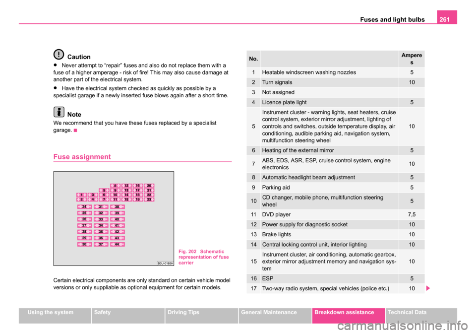
Certain electrical components are only standard on certain vehicle model
versions or only suppliable as optional equipment for certain models.
Fig. 202 Schematic
representation of fuse
carrier
No.Ampere
s
1Heatable windscreen washing nozzles5
2Turn signals10
3Not assigned
4Licence plate light5
5
Instrument cluster - warning lights, seat heaters, cruise
control system, exterior mirror adjustment, lighting of
controls and switches, outside temperature display, air
conditioning, audible parking aid, navigation system,
multifunction steering wheel
10
6Heating of the external mirror5
7ABS, EDS, ASR, ESP, cruise control system, engine
electronics10
8Automatic headlight beam adjustment5
9Parking aid5
10CD changer, mobile phone, multifunction steering
wheel5
11DVD player7,5
12Power supply for diagnostic socket10
13Brake lights10
14Central locking control unit, interior lighting10
15Instrument cluster, air conditioning, automatic gearbox,
exterior mirror adjustment memory and navigation sys-
tem10
16ESP5
17Two-way radio system, special vehicles (police etc.)10
NKO B5 20.book Page 261 Monday, July 3, 2006 2:09 PM
Page 263 of 281
Fuses and light bulbs
262
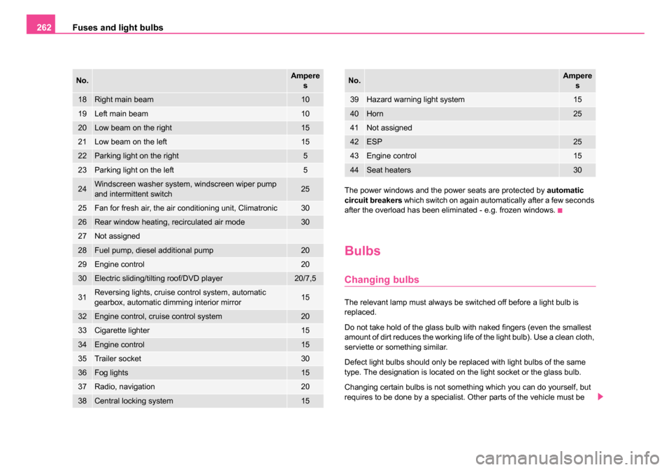
The power windows and the power seats are protected by automatic
circuit breakers which switch on again automatically after a few seconds
after the overload has been eliminated - e.g. frozen windows.
Bulbs
Changing bulbs
The relevant lamp must always be switched off before a light bulb is
replaced.
Do not take hold of the glass bulb with naked fingers (even the smallest
amount of dirt reduces the working life of the light bulb). Use a clean cloth,
serviette or something similar.
Defect light bulbs should only be replaced with light bulbs of the same
type. The designation is located on the light socket or the glass bulb.
Changing certain bulbs is not something which you can do yourself, but
requires to be done by a specialist. Other parts of the vehicle must be
18Right main beam10
19Left main beam10
20Low beam on the right15
21Low beam on the left15
22Parking light on the right5
23Parking light on the left5
24Windscreen washer system, windscreen wiper pump
and intermittent switch25
25Fan for fresh air, the air conditioning unit, Climatronic30
26Rear window heating, recirculated air mode30
27Not assigned
28Fuel pump, diesel additional pump20
29Engine control20
30Electric sliding/tilting roof/DVD player20/7,5
31Reversing lights, cruise control system, automatic
gearbox, automatic dimming interior mirror15
32Engine control, cruise control system20
33Cigarette lighter15
34Engine control15
35Trailer socket30
36Fog lights15
37Radio, navigation20
38Central locking system15
No.Ampere s
39Hazard warning light system15
40Horn25
41Not assigned
42ESP25
43Engine control15
44Seat heaters30
No.Amperes
NKO B5 20.book Page 262 Monday, July 3, 2006 2:09 PM