load SKODA SUPERB 2008 Owner´s Manual
[x] Cancel search | Manufacturer: SKODA, Model Year: 2008, Model line: SUPERB, Model: SKODA SUPERB 2008Pages: 252, PDF Size: 16.33 MB
Page 139 of 252
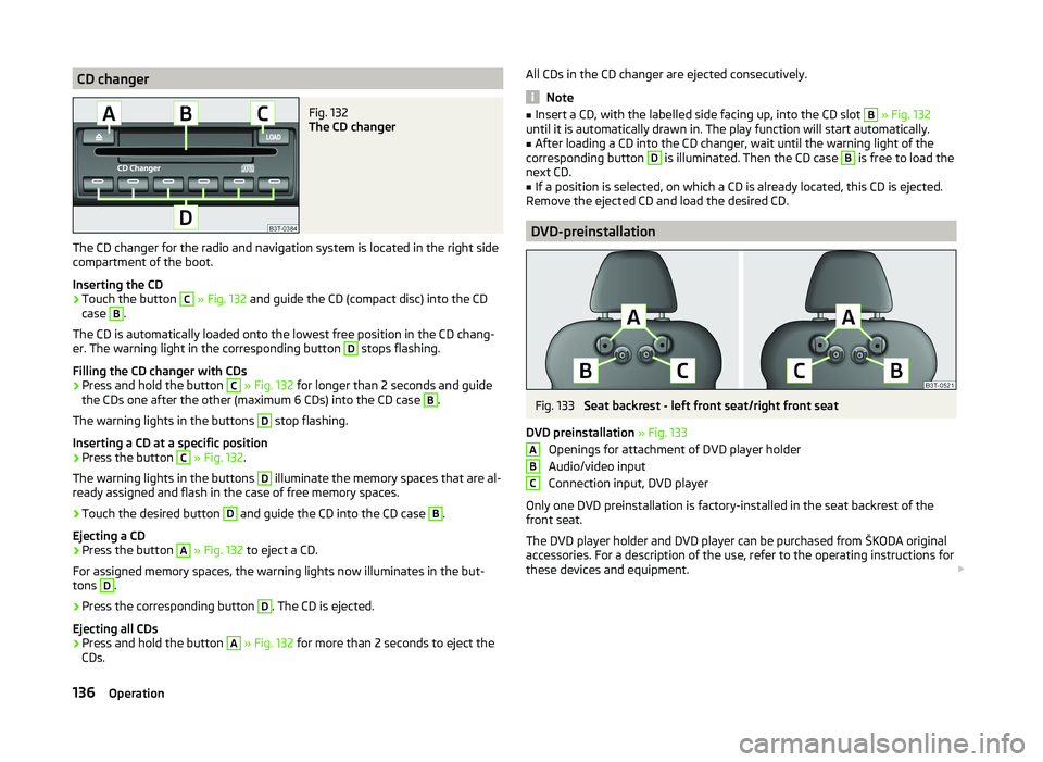
CD changerFig. 132
The CD changer
The CD changer for the radio and navigation system is located in the right side
compartment of the boot.
Inserting the CD
›
Touch the button
C
» Fig. 132 and guide the CD (compact disc) into the CD
case
B
.
The CD is automatically loaded onto the lowest free position in the CD chang-
er. The warning light in the corresponding button
D
stops flashing.
Filling the CD changer with CDs
›
Press and hold the button
C
» Fig. 132 for longer than 2 seconds and guide
the CDs one after the other (maximum 6 CDs) into the CD case
B
.
The warning lights in the buttons
D
stop flashing.
Inserting a CD at a specific position
›
Press the button
C
» Fig. 132 .
The warning lights in the buttons
D
illuminate the memory spaces that are al-
ready assigned and flash in the case of free memory spaces.
›
Touch the desired button
D
and guide the CD into the CD case
B
.
Ejecting a CD
›
Press the button
A
» Fig. 132 to eject a CD.
For assigned memory spaces, the warning lights now illuminates in the but-
tons
D
.
›
Press the corresponding button
D
. The CD is ejected.
Ejecting all CDs
›
Press and hold the button
A
» Fig. 132 for more than 2 seconds to eject the
CDs.
All CDs in the CD changer are ejected consecutively.
Note
■ Insert a CD, with the labelled side facing up, into the CD slot B » Fig. 132
until it is automatically drawn in. The play function will start automatically.■
After loading a CD into the CD changer, wait until the warning light of the
corresponding button
D
is illuminated. Then the CD case
B
is free to load the
next CD.
■
If a position is selected, on which a CD is already located, this CD is ejected.
Remove the ejected CD and load the desired CD.
DVD-preinstallation
Fig. 133
Seat backrest - left front seat/right front seat
DVD preinstallation » Fig. 133
Openings for attachment of DVD player holder
Audio/video input
Connection input, DVD player
Only one DVD preinstallation is factory-installed in the seat backrest of the
front seat.
The DVD player holder and DVD player can be purchased from ŠKODA original
accessories. For a description of the use, refer to the operating instructions for
these devices and equipment.
ABC136Operation
Page 141 of 252
Driving
Starting off and Driving
Starting and stopping the engine using the key
Introduction
This chapter contains information on the following subjects:
Electronic immobilizer
139
Ignition Switch
139
Starting the engine
139
Stopping the engine
140
Starting and stopping the engine on vehicles with the KESSY sys-
tem » page 140 .
The engine can only be started using a correctly coded original key.
The engine running noises may louder at first be louder for a short time after
starting the cold engine. This is quite normal and is not an operating problem.
WARNING■ When the vehicle is travelling with the engine off, the ignition key must
always be in position 2 » Fig. 134 on page 139 (ignition switched on). This
position is confirmed by the appearance of certain indicator lamps in the in-
strument cluster. ■If the key is not in position 2,
it could unexpectedly lock the steering -
danger of accident!
■
Only pull the ignition key from the ignition lock when the vehicle has
come to a complete stop (by applying the handbrake). Otherwise, the steer-
ing could be blocked – risk of accident!
■
Never leave the key in the vehicle when you exit the vehicle. Unauthor-
ized persons, such as children, for example, could lock the car, turn on the
ignition or start the engine - there is a danger of injury and accidents!
■
Never leave the vehicle unattended with the engine running - there is
risk of accident, damage or theft!
■
Never switch off the engine before the vehicle is stationary – risk of acci-
dent!
WARNING■ Never leave the engine running in unventilated or closed rooms. The en-
gine's exhaust gases also contain the odourless and colourless carbon
monoxide, a poisonous gas – risk of death. ■ Carbon monoxide can cause unconsciousness and death.■
Do not leave any items (e.g. cleaning cloths or tools) in the engine com-
partment. This presents a fire hazard and the risk of engine damage.
■
Never cover the engine with additional insulation material (e.g. with a
cover) – risk of fire!
CAUTION
■ The starter must only be operated when the engine is not running and the
vehicle is at a standstill. The starter or engine can be damaged if the starter is
activated when the engine is running 3
» Fig. 134 on page 139 .
■
Do not tow start the engine – there is a risk of damaging the engine and the
catalytic converter. The battery from another vehicle can be used as a jump-
start aid » page 211 , Jump-starting .
CAUTION
■
Avoid high engine revolutions, full throttle and high engine loads before the
engine has reached its operating temperature – risk of damaging the engine!■
Do not switch the engine off immediately at the end of your journey after the
engine has been operated over a prolonged period at high loads but leave it to
run at an idling speed for about 1 minute. This prevents any possible accumula-
tion of heat when the engine is switched off.
For the sake of the environment
Do not warm up the engine while the vehicle is stationary. If possible, start
your journey as soon as the engine has started. Through this the engine rea-
ches its operating temperature more rapidly and the pollutant emissions are
lower.
Note
After switching off the ignition, the radiator fan can intermittently continue to
operate for approx. 10 minutes.138Driving
Page 144 of 252
CAUTION■Avoid high engine revolutions, full throttle and high engine loads before the
engine has reached its operating temperature – risk of damaging the engine!■
Do not switch the engine off immediately at the end of your journey after the
engine has been operated over a prolonged period at high loads but leave it to
run at an idling speed for about 1 minute. This prevents any possible accumula-
tion of heat when the engine is switched off.
For the sake of the environment
Do not warm up the engine while the vehicle is stationary. If possible, start
your journey as soon as the engine has started. Through this the engine rea-
ches its operating temperature more rapidly and the pollutant emissions are
lower.
Note
■ The system is protected against inadvertently switching off the engine while
driving, this means that the engine can only be switched off in an emergen-
cy » page 143 .■
After switching off the ignition, the radiator fan can intermittently continue
to operate for approx. 10 minutes.
■
Under certain circumstances (e.g. after switching off the ignition and opening
the driver's door), the steering is enabled only when the ignition is switched on
or the engine is started.
Steering lock / unlock
Fig. 135
Starter button
Read and observe and on page 140 first.
The steering lock (steering lock) deters attempted theft of your vehicle.
Locking
›
Stop the vehicle.
› Switch off the engine or the ignition by pressing the starter button
» Fig. 135.›Open the driver door.
The steering is locked automatically.
If the driver's door is opened and the ignition is switched off afterwards, the
steering is only locked after the vehicle is locked.
Unlocking›
Open the driver's door and get into the vehicle.
›
Close the driver's door.
The steering is unlocked within 2 seconds.
If the system does not unlock the steering at the first time (for example when
the front wheels are in contact with an obstacle), then two more unlocking at-
tempts are performed automatically.
If the steering is still not unlocked, then the following message is displayed on the display of the instrument cluster.
Move the steering wheel!
MOVE STEERING WHEEL
Slightly move the steering wheel and the system will make up to 3 more at-
tempts to unlock after 2 seconds. At the same time, the warning light flash-
es.
If the steering is still not unlocked, to try to eliminate the possible cause and
then repeat the unlocking attempt.
Ignition on/off
Read and observe
and on page 140 first.
›
Press the starter button » Fig. 135 on page 141 briefly.
The ignition is switched on or off.
On vehicles fitted with a manual transmission, the clutch pedal must not be
depressed while switching the ignition on or off, otherwise the system would
try to start.
On vehicles fitted with a automatic transmission, the brake pedal must not be
depressed while switching the ignition on or off, otherwise the system would
try to start.
141Starting off and Driving
Page 146 of 252
Emergency ignition shutoff systemRead and observe
and on page 140 first.
The ignition can be turned off in an emergency even when travelling at a
speed of more than 2 km / hr.
›
Press the starter button » Fig. 135 on page 141 for longer than 1 second or
twice within 1 second.
After emergency stop of the ignition, the steering is unlocked.
Brakes
Introduction
This chapter contains information on the following subjects:
Information on braking
143
Handbrake
144WARNING■ Greater physical effort is required for braking when the engine is switch-
ed off – risk of accident!■
The clutch pedal must be depressed when braking on a vehicle with man-
ual transmission, when the vehicle is in gear and at low revs. Otherwise,
the function of the brake booster may be impaired – risk of accident!
■
When leaving the vehicle, never leave persons who might, for example,
release the handbrake or take the vehicle out of gear unattended in the ve-
hicle. The vehicle could then start to move – risk of accident!
WARNINGIn the case of damage to the standard fitted front spoiler or if retrofitting
another front spoiler, hub caps etc. » page 173, Services, modifications and
technical alterations , make sure that the air supply to the front brakes is
not affected. The front brakes may overheat, which can have a negative im-
pact on the functioning of the braking system – there is a risk of an acci-
dent!CAUTION■ Observe the recommendations on the new brake pads » page 149.■Never let the brakes slip with light pressure on the pedal if braking is not
necessary. This causes the brakes to overheat and can also result in a longer
braking distance and excessive wear.
Information on braking
Read and observe
and on page 143 first.
If the brakes are applied in full and the control unit for the braking system con-siders the situation to be dangerous for the following traffic, the brake light
flashes automatically.
After the speed was reduced below around 10 km/h or the vehicle was stop-
ped, the brake light stops flashing and the hazard warning light system
switches on. The hazard warning light system is switched off automatically af- ter accelerating or driving off again.
Before travelling a long distance down a steep gradient, reduce speed and
shift into the next lowest gear. As a result, the braking effect of the engine will
be used, reducing the load on the brakes. Any additional braking should be
completed intermittently, not continuously.
Wear-and-tear
The wear of the brake pads is dependent on the operating conditions and driv- ing style.
The brake pads wear more quickly if a lot of journeys are completed in towns
and over short distances or if a very sporty style of driving is adopted.
Under these severe conditions , the thickness of the brake pads must also be
checked by a specialist garage between services.
Wet roads or road salt
The performance of the brakes can be delayed as the brake discs and brake
pads may be moist or have a coating of ice or layer of salt on them in winter.
The brakes are cleaned and dried by applying the brakes several times.
Corrosion
Corrosion on the brake discs and dirt on the brake pads occur if the vehicle has
been parked for a long period and if you do not make much use of the braking
system. The brakes are cleaned by applying the brakes several times.
143Starting off and Driving
Page 149 of 252
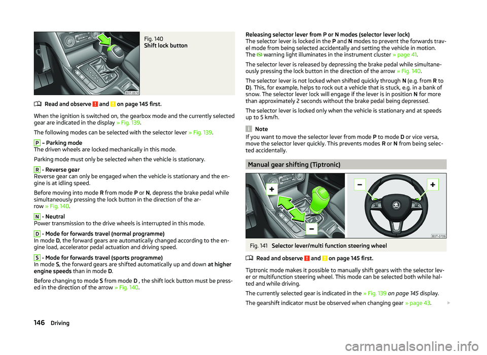
Fig. 140
Shift lock button
Read and observe and on page 145 first.
When the ignition is switched on, the gearbox mode and the currently selectedgear are indicated in the display » Fig. 139.
The following modes can be selected with the selector lever » Fig. 139.
P
– Parking mode
The driven wheels are locked mechanically in this mode.
Parking mode must only be selected when the vehicle is stationary.
R
- Reverse gear
Reverse gear can only be engaged when the vehicle is stationary and the en-
gine is at idling speed.
Before moving into mode R from mode P or N, depress the brake pedal while
simultaneously pressing the lock button in the direction of the ar-
row » Fig. 140 .
N
- Neutral
Power transmission to the drive wheels is interrupted in this mode.
D
- Mode for forwards travel (normal programme)
In mode D, the forward gears are automatically changed according to the en-
gine load, accelerator pedal actuation and driving speed.
S
- Mode for forwards travel (sports programme)
In mode S, the forward gears are shifted automatically up and down at higher
engine speeds than in mode D.
Before changing to mode S from mode D , the shift lock button must be press-
ed in the direction of the arrow » Fig. 140.
Releasing selector lever from P or N modes (selector lever lock)
The selector lever is locked in the P and N modes to prevent the forwards trav-
el mode from being selected accidentally and setting the vehicle in motion.
The
warning light illuminates in the instrument cluster » page 41.
The selector lever is released by depressing the brake pedal while simultane-
ously pressing the lock button in the direction of the arrow » Fig. 140.
The selector lever is not locked when shifted quickly through N (e.g. from R to
D ). This, for example, helps to rock out a vehicle that is stuck, e.g. in a bank of
snow. The selector lever lock will engage if the lever is in position N for more
than approximately 2 seconds without the brake pedal being depressed.
The selector lever is locked only when the vehicle is stationary and at speeds
up to 5 km/h.
Note
If you want to move the selector lever from mode P to mode D or vice versa,
move the selector lever quickly. This prevents modes R or N from being selec-
ted accidentally.
Manual gear shifting (Tiptronic)
Fig. 141
Selector lever/multi function steering wheel
Read and observe
and on page 145 first.
Tiptronic mode makes it possible to manually shift gears with the selector lev-
er or multifunction steering wheel. This mode can be selected both while hal-
ted and while driving.
The currently selected gear is indicated in the » Fig. 139 on page 145 display.
The gearshift indicator must be observed when changing gear » page 43.
146Driving
Page 150 of 252
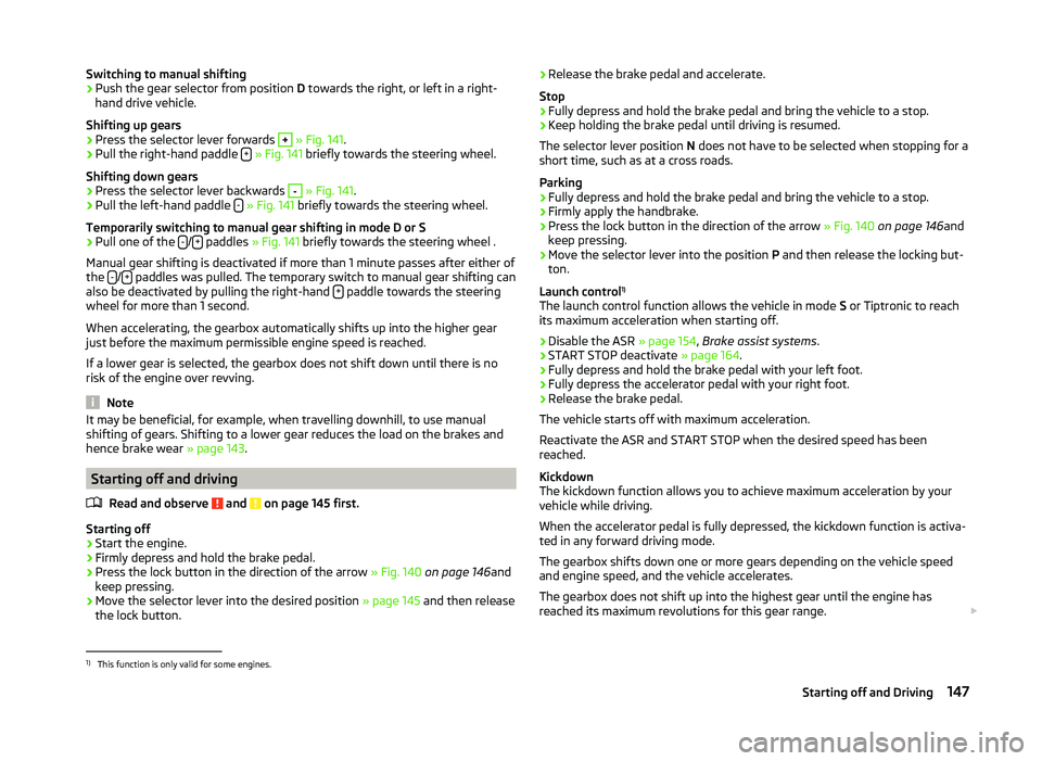
Switching to manual shifting›Push the gear selector from position D towards the right, or left in a right-
hand drive vehicle.
Shifting up gears›
Press the selector lever forwards
+
» Fig. 141 .
›
Pull the right-hand paddle +
» Fig. 141 briefly towards the steering wheel.
Shifting down gears
›
Press the selector lever backwards
-
» Fig. 141 .
›
Pull the left-hand paddle -
» Fig. 141 briefly towards the steering wheel.
Temporarily switching to manual gear shifting in mode D or S
›
Pull one of the -/+ paddles
» Fig. 141 briefly towards the steering wheel .
Manual gear shifting is deactivated if more than 1 minute passes after either of
the -
/+ paddles was pulled. The temporary switch to manual gear shifting can
also be deactivated by pulling the right-hand + paddle towards the steering
wheel for more than 1 second.
When accelerating, the gearbox automatically shifts up into the higher gear
just before the maximum permissible engine speed is reached.
If a lower gear is selected, the gearbox does not shift down until there is no risk of the engine over revving.
Note
It may be beneficial, for example, when travelling downhill, to use manual
shifting of gears. Shifting to a lower gear reduces the load on the brakes and
hence brake wear » page 143.
Starting off and driving
Read and observe
and on page 145 first.
Starting off
›
Start the engine.
›
Firmly depress and hold the brake pedal.
›
Press the lock button in the direction of the arrow » Fig. 140 on page 146 and
keep pressing.
›
Move the selector lever into the desired position » page 145 and then release
the lock button.
› Release the brake pedal and accelerate.
Stop›
Fully depress and hold the brake pedal and bring the vehicle to a stop.
›
Keep holding the brake pedal until driving is resumed.
The selector lever position N does not have to be selected when stopping for a
short time, such as at a cross roads.
Parking
›
Fully depress and hold the brake pedal and bring the vehicle to a stop.
›
Firmly apply the handbrake.
›
Press the lock button in the direction of the arrow » Fig. 140 on page 146 and
keep pressing.
›
Move the selector lever into the position P and then release the locking but-
ton.
Launch control 1)
The launch control function allows the vehicle in mode S or Tiptronic to reach
its maximum acceleration when starting off.
›
Disable the ASR » page 154, Brake assist systems .
›
START STOP deactivate » page 164.
›
Fully depress and hold the brake pedal with your left foot.
›
Fully depress the accelerator pedal with your right foot.
›
Release the brake pedal.
The vehicle starts off with maximum acceleration.
Reactivate the ASR and START STOP when the desired speed has been
reached.
Kickdown
The kickdown function allows you to achieve maximum acceleration by your
vehicle while driving.
When the accelerator pedal is fully depressed, the kickdown function is activa-
ted in any forward driving mode.
The gearbox shifts down one or more gears depending on the vehicle speed
and engine speed, and the vehicle accelerates.
The gearbox does not shift up into the highest gear until the engine has
reached its maximum revolutions for this gear range.
1)
This function is only valid for some engines.
147Starting off and Driving
Page 154 of 252
Always ensure the tyre inflation pressure is correct » page 198. If the pressure
is too low, the tyres will have to overcome a higher rolling resistance. This will
not only increase fuel consumption but also tyre wear and the driving behav-
iour will worsen.
Always check the tyre inflation pressure when the tyres are cold.
Avoiding unnecessary ballast
Read and observe
on page 149 first.
Transporting ballast costs fuel.
Each kilogramme of weight increases the fuel consumption. Therefore we rec-
ommend carrying no unnecessary weight.
It is particularly in town traffic, when one is accelerating quite often, that the
vehicle weight will have a significant effect upon the fuel consumption. A rule
of thumb here is that an increase in weight of 100 kilograms will cause an in-
crease in fuel consumption of about 1 litre/100 kilometres.
At a speed of 100 - 120 km/h, a vehicle fitted with a roof rack cross member
without a load will use about 10 % more fuel than normal due to the increased
aerodynamic drag.
Regular maintenance
Read and observe
on page 149 first.
A poorly tuned engine uses an unnecessarily high amount of fuel.
By having your vehicle regularly maintained by a specialist garage, you create
the conditions needed for economical driving. The maintenance state of your
vehicle has a positive effect on traffic safety and value retention
A poorly tuned engine can result in a fuel consumption which is 10 % higher than normal.
Check the oil level at regular intervals, e.g. when filling up. Oil consumption is
dependent to a considerable extent on the load and speed of the engine. Oil
consumption could be as high as 0.5 litres/1 000 km depending on your style
of driving.
It is quite normal that a new engine has higher oil consumption at first, and
reaches its lowest level only after a certain running in time. The oil consump-
tion of a new vehicle can therefore only be correctly assessed after driving
about 5,000 km.
For the sake of the environment■ Additional improvements to the fuel economy can be made by using synthet-
ic low viscosity oils.■
Regularly check the ground under the vehicle. Have your vehicle inspected by
a specialist garage if you find any stains caused by oil or other fluids on the
ground.
Note
We recommend that your vehicle be serviced on a regular basis by a ŠKODA
service partner.
Saving electrical energy
Read and observe
on page 149 first.
When the engine is running, the alternator generates and supplies electricalpower. If more electrical components of the electrical system are switched on,
more fuel is needed to operate the alternator. We therefore recommend
switching off electrical components if these are no longer required.
Environmental compatibility
Read and observe
on page 149 first.
Environmental protection has played a major role in the design, material selec-
tion and production of your new ŠKODA. Particular emphasis has been placed
on the following points.
Design measures › Joints designed to be easily detached.
› Simplified disassembly due to the modular structure system.
› Improved purity of different classes of materials.
› Identification of all plastic parts in accordance with VDA Recommendation
260.
› Reduced fuel consumption and exhaust emission CO
2.
› Minimum fuel leakage during accidents.
› Reduced noise.
Choice of materials
› Extensive use of recyclable material.
› Air conditioning filled with CFC-free refrigerant.
› No cadmium.
151Starting off and Driving
Page 169 of 252
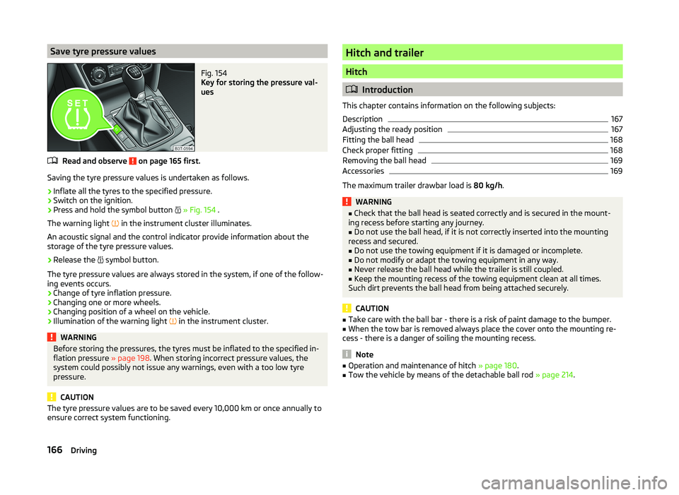
Save tyre pressure valuesFig. 154
Key for storing the pressure val-
ues
Read and observe on page 165 first.
Saving the tyre pressure values is undertaken as follows.
›
Inflate all the tyres to the specified pressure.
›
Switch on the ignition.
›
Press and hold the symbol button
» Fig. 154 .
The warning light in the instrument cluster illuminates.
An acoustic signal and the control indicator provide information about the
storage of the tyre pressure values.
›
Release the symbol button.
The tyre pressure values are always stored in the system, if one of the follow-
ing events occurs.
› Change of tyre inflation pressure.
› Changing one or more wheels.
› Changing position of a wheel on the vehicle.
› Illumination of the warning light
in the instrument cluster.
WARNINGBefore storing the pressures, the tyres must be inflated to the specified in-
flation pressure » page 198. When storing incorrect pressure values, the
system could possibly not issue any warnings, even with a too low tyre
pressure.
CAUTION
The tyre pressure values are to be saved every 10,000 km or once annually to
ensure correct system functioning.Hitch and trailer
Hitch
Introduction
This chapter contains information on the following subjects:
Description
167
Adjusting the ready position
167
Fitting the ball head
168
Check proper fitting
168
Removing the ball head
169
Accessories
169
The maximum trailer drawbar load is 80 kg/h.
WARNING■
Check that the ball head is seated correctly and is secured in the mount-
ing recess before starting any journey.■
Do not use the ball head, if it is not correctly inserted into the mounting
recess and secured.
■
Do not use the towing equipment if it is damaged or incomplete.
■
Do not modify or adapt the towing equipment in any way.
■
Never release the ball head while the trailer is still coupled.
■
Keep the mounting recess of the towing equipment clean at all times.
Such dirt prevents the ball head from being attached securely.
CAUTION
■ Take care with the ball bar - there is a risk of paint damage to the bumper.■When the tow bar is removed always place the cover onto the mounting re-
cess - there is a danger of soiling the mounting recess.
Note
■ Operation and maintenance of hitch » page 180.■Tow the vehicle by means of the detachable ball rod » page 214.166Driving
Page 172 of 252

Removing the ball headFig. 159
Unlock the operating lever of the ball head/removing the ball
head
Read and observe
and on page 166 first.
›
Remove cover
1
» Fig. 159 from the lock in the direction of the arrow.
›
Insert the key into the lock, so that its green marking is pointing upwards.
›
Turn the key
2
180° to the left so that its red marker points upward.
›
Grasp the ball head from underneath.
›
Press the release pin
3
as far as the stop in the direction of the arrow and
at the same time push the lever
4
downwards as far as it will go in the di-
rection of the arrow.
The ball head is released in this position and falls freely into the hand. If it
does not fall freely into the hand, use your other hand to push it upwards.
At the same time, the ball head latches into the ready position and is thus
ready to be re-inserted into the mounting recess »
.
›
Place the cap
4
» Fig. 155 on page 167 onto the mounting recess.
WARNINGNever allow the ball head to remain unsecured in the boot. This could
cause damage to the boot upon sudden braking, and could put the safety
of the occupants at risk.CAUTION■ If the lever is held firmly and not pushed downwards as far as it can go, it will
go back up after the ball head is removed and will not latch into the ready po-
sition. The ball head then needs to be brought into this position before the
next time it is fitted.■
Tuck the ball bar in the ready position, with the golden key up, in the box -
otherwise there is a risk of damage to the key!
■
Do not use excessive force when handling the operating lever (e.g. do not
step on it).
Note
■ We recommend that you put the protective cap on the ball before removing
the ball head.■
Clean any dirt from the ball head before stowing it away in the box with the
vehicle tool kit.
Accessories
Fig. 160
Representation of the maximum
permissible level of the ball head
of the towing hitch and the per-
missible total weight of the ac-
cessories including the load de-
pending on the load center of
gravity
Read and observe and on page 166 first.
An accessory can mounted on the ball head of the towing hitch (e.g. bike carri-
ers).
If this accessory is used, the maximum permissible overhang of the ball head
of the towing hitch and the permissible gross vehicle weight of the accesso-
ries including load are to be checked.
The maximum permissible overhang of the ball head of the towing hitch is 70
cm » Fig. 160 .
The total permitted weight of the accessory including load changes with in-
creasing distance of the centre of gravity of the load from the ball head of the
towing hitch.
169Hitch and trailer
Page 173 of 252

Distance of the centre of gravity ofthe load from the ball headPermissible total weight of the ac- cessory, including load0 cm80 kg30 cm75 kg60 cm35 kg70 cm0 kgWARNING■Never exceed the permissible gross weight of the accessory including
load - there is a risk of damaging the ball head of the towing hitch.■
Never exceed the permissible overhang of the ball head of the towing
hitch - there is a risk of damaging the ball head of the towing hitch.
Note
We recommend that you use accessories from ŠKODA Original Accessories.
Trailer
Introduction
This chapter contains information on the following subjects:
Attaching and detaching trailers
170
Loading a trailer
171
Towing a trailer
171
Trailer stabilisation (TSA)
172
Anti-theft alarm system
172
If your vehicle has already been factory fitted with towing equipment or is fit-
ted with towing equipment from ŠKODA Original Accessories, then it meets all
of the technical requirements and national legal provisions for towing a trailer.
Note
If there is an error in the trailer lighting system, check the fuses in the fuse box
in the dashboard » page 220.Attaching and detaching trailersFig. 161
Swivel out the 13-pin power
socket, safety eyelet
Coupling
›
Install the tow bar.
›
Grip the 13-pin socket at point
A
and swing out in the direction of ar-
row » Fig. 161 .
›
Lift off protective cap
5
» Fig. 155 on page 167 towards the top.
›
Place the trailer onto the ball.
›
Insert the trailer cable into the 13-pin socket.
If the trailer that is to be towed has a 7-pin connector, you can use a suitable
adapter from ŠKODA Original Accessories to establish a connection to the elec-
tricity.
›
Hook the breakaway cable of the trailer to the security lock slot
B
.
The breakaway cable of the trailer has to sag when mounted into the security
lock slot for all trailer positions relative to the vehicle (sharp curves, reverse
driving and the like).
Uncoupling
The uncoupling of the trailer is carried out in reverse order.
›
Unhook the breakaway cable of the trailer from the security lock slot
B
» Fig. 161 .
›
Pull the trailer cable out of the 13-pin socket.
›
Remove the trailer from the ball head.
›
Place the cover
5
on the ball head » Fig. 155 on page 167 .
›
Grip the 13-pin socket at point
A
and swing in the opposite direction to the
arrow » Fig. 161 .
170Driving