tow bar SKODA SUPERB 2008 Owner´s Manual
[x] Cancel search | Manufacturer: SKODA, Model Year: 2008, Model line: SUPERB, Model: SKODA SUPERB 2008Pages: 252, PDF Size: 16.33 MB
Page 32 of 252
Operation
Cockpit
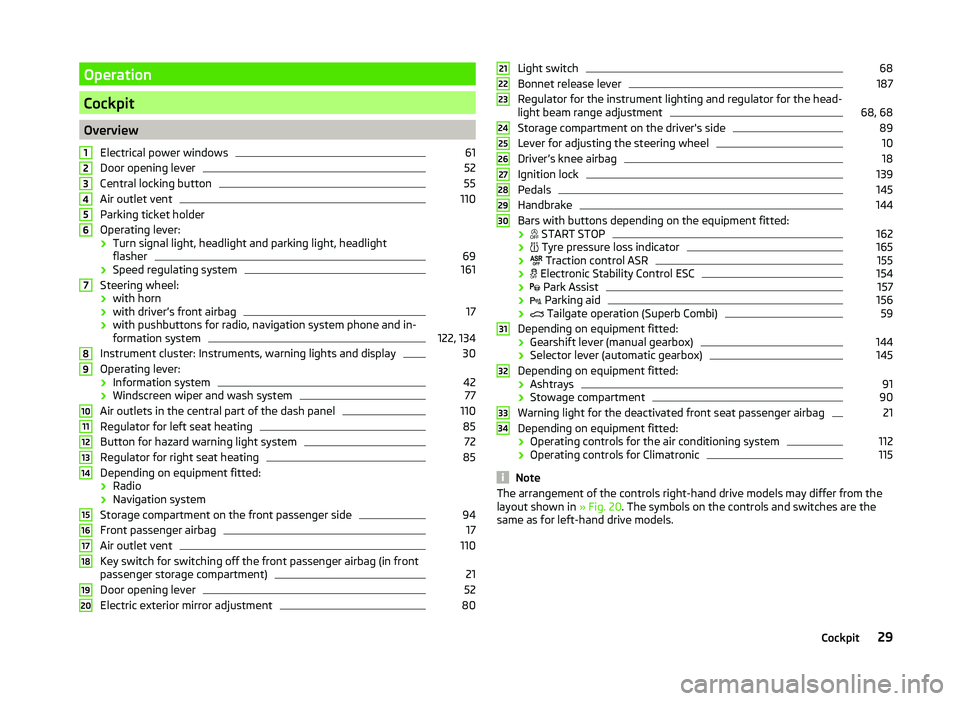
OverviewElectrical power windows
61
Door opening lever
52
Central locking button
55
Air outlet vent
110
Parking ticket holder
Operating lever: › Turn signal light, headlight and parking light, headlight
flasher
69
› Speed regulating system
161
Steering wheel:
› with horn
› with driver’s front airbag
17
› with pushbuttons for radio, navigation system phone and in-
formation system
122, 134
Instrument cluster: Instruments, warning lights and display
30
Operating lever:
› Information system
42
›Windscreen wiper and wash system
77
Air outlets in the central part of the dash panel
110
Regulator for left seat heating
85
Button for hazard warning light system
72
Regulator for right seat heating
85
Depending on equipment fitted:
› Radio
› Navigation system
Storage compartment on the front passenger side
94
Front passenger airbag
17
Air outlet vent
110
Key switch for switching off the front passenger airbag (in front
passenger storage compartment)
21
Door opening lever
52
Electric exterior mirror adjustment
801234567891011121314151617181920Light switch68
Bonnet release lever
187
Regulator for the instrument lighting and regulator for the head-
light beam range adjustment
68, 68
Storage compartment on the driver's side
89
Lever for adjusting the steering wheel
10
Driver’s knee airbag
18
Ignition lock
139
Pedals
145
Handbrake
144
Bars with buttons depending on the equipment fitted:
›
START STOP
162
›
Tyre pressure loss indicator
165
›
Traction control ASR
155
›
Electronic Stability Control ESC
154
›
Park Assist
157
›
Parking aid
156
›
Tailgate operation (Superb Combi)
59
Depending on equipment fitted:
› Gearshift lever (manual gearbox)
144
›Selector lever (automatic gearbox)
145
Depending on equipment fitted:
› Ashtrays
91
›Stowage compartment
90
Warning light for the deactivated front seat passenger airbag
21
Depending on equipment fitted:
› Operating controls for the air conditioning system
112
›
Operating controls for Climatronic
115
Note
The arrangement of the controls right-hand drive models may differ from the
layout shown in » Fig. 20. The symbols on the controls and switches are the
same as for left-hand drive models.212223242526272829303132333429Cockpit
Page 169 of 252
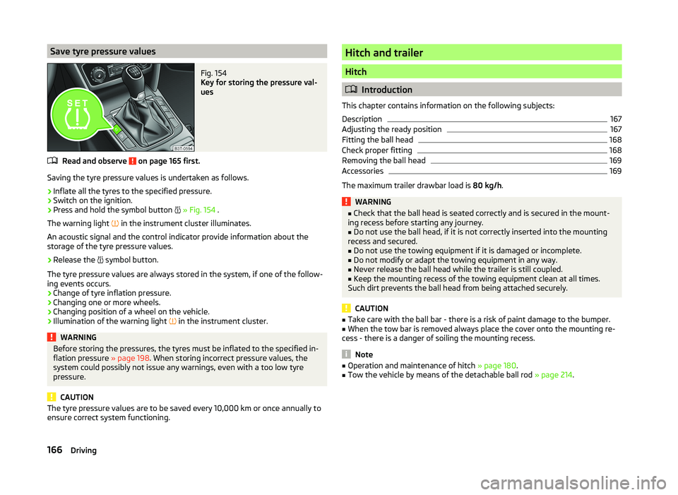
Save tyre pressure valuesFig. 154
Key for storing the pressure val-
ues
Read and observe on page 165 first.
Saving the tyre pressure values is undertaken as follows.
›
Inflate all the tyres to the specified pressure.
›
Switch on the ignition.
›
Press and hold the symbol button
» Fig. 154 .
The warning light in the instrument cluster illuminates.
An acoustic signal and the control indicator provide information about the
storage of the tyre pressure values.
›
Release the symbol button.
The tyre pressure values are always stored in the system, if one of the follow-
ing events occurs.
› Change of tyre inflation pressure.
› Changing one or more wheels.
› Changing position of a wheel on the vehicle.
› Illumination of the warning light
in the instrument cluster.
WARNINGBefore storing the pressures, the tyres must be inflated to the specified in-
flation pressure » page 198. When storing incorrect pressure values, the
system could possibly not issue any warnings, even with a too low tyre
pressure.
CAUTION
The tyre pressure values are to be saved every 10,000 km or once annually to
ensure correct system functioning.Hitch and trailer
Hitch
Introduction
This chapter contains information on the following subjects:
Description
167
Adjusting the ready position
167
Fitting the ball head
168
Check proper fitting
168
Removing the ball head
169
Accessories
169
The maximum trailer drawbar load is 80 kg/h.
WARNING■
Check that the ball head is seated correctly and is secured in the mount-
ing recess before starting any journey.■
Do not use the ball head, if it is not correctly inserted into the mounting
recess and secured.
■
Do not use the towing equipment if it is damaged or incomplete.
■
Do not modify or adapt the towing equipment in any way.
■
Never release the ball head while the trailer is still coupled.
■
Keep the mounting recess of the towing equipment clean at all times.
Such dirt prevents the ball head from being attached securely.
CAUTION
■ Take care with the ball bar - there is a risk of paint damage to the bumper.■When the tow bar is removed always place the cover onto the mounting re-
cess - there is a danger of soiling the mounting recess.
Note
■ Operation and maintenance of hitch » page 180.■Tow the vehicle by means of the detachable ball rod » page 214.166Driving
Page 170 of 252

DescriptionFig. 155
Carrier for the towing device / tow bar
Read and observe
and on page 166 first.
The ball head can be removed and is kept in the spare wheel well or in a com-
partment for the spare wheel in the luggage compartment.
Support for the towing device and tow bar » Fig. 155
13-pin power socket
Safety eyelet
Mounting recess
Cap
Dust cap
Ball head
Operating lever
Lock cap
Release pin
Key
locking ball
Note
If you lose the key, please get in touch with a specialist garage.1234567891011Adjusting the ready positionFig. 156
Setting the ready position/ready position
Read and observe
and on page 166 first.
The coupling ball bar must be set prior to installation in the standby position.
If this is not in the ready position, then this must be set to the standby posi-
tion as follows.
›
Grip the ball head below the protective cap
2
.
›
Remove the cap from the lock.
›
Insert the key into the lock, so that its green marking is pointing upwards.
›
Turn key
1
in direction of the arrow, so that the red marking is facing up-
wards » Fig. 156 .
›
Press the release pin
3
as far as the stop in the direction of the arrow and
at the same time push the lever
4
downwards as far as it will go in the di-
rection of the arrow.
The operating lever remains locked in this position.
CAUTION
In the ready position, the key cannot be removed nor turned to a different po-
sition.167Hitch and trailer
Page 171 of 252

Fitting the ball headFig. 157
Insert the ball head/lock the lock, and put the lock cover on
Read and observe
and on page 166 first.
›
Pull cap
4
» Fig. 155 on page 167 downwards.
›
Adjust the ball head to the ready position » page 167.
›
Grip the tow bar from underneath » Fig. 157 and insert into the mounting re-
cess until you hear it click into place » .
The operating lever
1
automatically turns upwards and the release pin
2
pops out (its red and green parts are visible) » .
If the operating lever
1
does not automatically emerge, or if the release pin
2
does not pop out, remove the ball head from the mounting recess by turn-
ing the lever downwards as far as it will go. Clean the tapered surfaces on the
ball head and the mounting recess.
›
Turn the key
3
180° to the right so that its green marker points upward.
›
Remove the key in the direction of the arrow.
›
Insert and press the cap
4
onto the lock in the direction of the arrow » .
›
Check the ball head for secure mounting » page 168.
WARNING■
Keep your hands outside the lever's range of motion when attaching the
ball head – there is a risk of fingers being injured!■
Never attempt to pull the operating lever upwards forcibly to turn the
key. Doing so would mean the ball head is not attached correctly.
CAUTION■ After removing the key, always replace the cover on the lock – there is a risk
of the lock getting dirty.■
Keep the mounting recess of the towing equipment clean at all times. Such
dirt prevents the ball head from being attached securely.
Check proper fitting
Fig. 158
Correctly secured ball head
Read and observe and on page 166 first.
Check that the ball head is fitted properly each time before use.
Correctly secured ball head » Fig. 158
Lever
1
is up as far as it will go » Fig. 158.
The release pin
2
is completely exposed (both its red and green parts are
visible).
The key is removed.
Cap
3
is on the lock.
The ball head does not come out of the mounting recess even after heavy
“shaking”.
WARNINGThe towing device can only be used when the tow bar is correctly locked –
there is the risk of an accident occurring.168Driving
Page 172 of 252

Removing the ball headFig. 159
Unlock the operating lever of the ball head/removing the ball
head
Read and observe
and on page 166 first.
›
Remove cover
1
» Fig. 159 from the lock in the direction of the arrow.
›
Insert the key into the lock, so that its green marking is pointing upwards.
›
Turn the key
2
180° to the left so that its red marker points upward.
›
Grasp the ball head from underneath.
›
Press the release pin
3
as far as the stop in the direction of the arrow and
at the same time push the lever
4
downwards as far as it will go in the di-
rection of the arrow.
The ball head is released in this position and falls freely into the hand. If it
does not fall freely into the hand, use your other hand to push it upwards.
At the same time, the ball head latches into the ready position and is thus
ready to be re-inserted into the mounting recess »
.
›
Place the cap
4
» Fig. 155 on page 167 onto the mounting recess.
WARNINGNever allow the ball head to remain unsecured in the boot. This could
cause damage to the boot upon sudden braking, and could put the safety
of the occupants at risk.CAUTION■ If the lever is held firmly and not pushed downwards as far as it can go, it will
go back up after the ball head is removed and will not latch into the ready po-
sition. The ball head then needs to be brought into this position before the
next time it is fitted.■
Tuck the ball bar in the ready position, with the golden key up, in the box -
otherwise there is a risk of damage to the key!
■
Do not use excessive force when handling the operating lever (e.g. do not
step on it).
Note
■ We recommend that you put the protective cap on the ball before removing
the ball head.■
Clean any dirt from the ball head before stowing it away in the box with the
vehicle tool kit.
Accessories
Fig. 160
Representation of the maximum
permissible level of the ball head
of the towing hitch and the per-
missible total weight of the ac-
cessories including the load de-
pending on the load center of
gravity
Read and observe and on page 166 first.
An accessory can mounted on the ball head of the towing hitch (e.g. bike carri-
ers).
If this accessory is used, the maximum permissible overhang of the ball head
of the towing hitch and the permissible gross vehicle weight of the accesso-
ries including load are to be checked.
The maximum permissible overhang of the ball head of the towing hitch is 70
cm » Fig. 160 .
The total permitted weight of the accessory including load changes with in-
creasing distance of the centre of gravity of the load from the ball head of the
towing hitch.
169Hitch and trailer
Page 173 of 252

Distance of the centre of gravity ofthe load from the ball headPermissible total weight of the ac- cessory, including load0 cm80 kg30 cm75 kg60 cm35 kg70 cm0 kgWARNING■Never exceed the permissible gross weight of the accessory including
load - there is a risk of damaging the ball head of the towing hitch.■
Never exceed the permissible overhang of the ball head of the towing
hitch - there is a risk of damaging the ball head of the towing hitch.
Note
We recommend that you use accessories from ŠKODA Original Accessories.
Trailer
Introduction
This chapter contains information on the following subjects:
Attaching and detaching trailers
170
Loading a trailer
171
Towing a trailer
171
Trailer stabilisation (TSA)
172
Anti-theft alarm system
172
If your vehicle has already been factory fitted with towing equipment or is fit-
ted with towing equipment from ŠKODA Original Accessories, then it meets all
of the technical requirements and national legal provisions for towing a trailer.
Note
If there is an error in the trailer lighting system, check the fuses in the fuse box
in the dashboard » page 220.Attaching and detaching trailersFig. 161
Swivel out the 13-pin power
socket, safety eyelet
Coupling
›
Install the tow bar.
›
Grip the 13-pin socket at point
A
and swing out in the direction of ar-
row » Fig. 161 .
›
Lift off protective cap
5
» Fig. 155 on page 167 towards the top.
›
Place the trailer onto the ball.
›
Insert the trailer cable into the 13-pin socket.
If the trailer that is to be towed has a 7-pin connector, you can use a suitable
adapter from ŠKODA Original Accessories to establish a connection to the elec-
tricity.
›
Hook the breakaway cable of the trailer to the security lock slot
B
.
The breakaway cable of the trailer has to sag when mounted into the security
lock slot for all trailer positions relative to the vehicle (sharp curves, reverse
driving and the like).
Uncoupling
The uncoupling of the trailer is carried out in reverse order.
›
Unhook the breakaway cable of the trailer from the security lock slot
B
» Fig. 161 .
›
Pull the trailer cable out of the 13-pin socket.
›
Remove the trailer from the ball head.
›
Place the cover
5
on the ball head » Fig. 155 on page 167 .
›
Grip the 13-pin socket at point
A
and swing in the opposite direction to the
arrow » Fig. 161 .
170Driving
Page 174 of 252
Exterior mirrors
You have to have additional exterior mirrors fitted if you are not able to see
the traffic behind the trailer with the standard rear-view mirrors. National legal
requirements must be observed.
Headlights
The front of the vehicle can be lifted when a trailer is being towed and the
headlights can dazzle other road users.
Adjust the headlight setting on the headlight range control » page 68, Operat-
ing the lights and the instrument illumination .WARNING■
Incorrect or improperly connected electrical installation can cause acci-
dents and serious injury due to electric shock.■
Work on the electrical system must only be carried out by specialist ga-
rages.
■
Never directly connect the trailer's electrical system with the electrical
connections for the tail lights or other current sources.
■
After coupling the trailer and connecting up the power socket, check the
rear lights on the trailer to ensure they are working.
■
The handbrake on the towing vehicle must be applied when coupling and
uncoupling the trailer.
■
Never use the safety eyelet for towing!
CAUTION
Incorrect or improperly connected electrical installations may cause malfunc-
tion of the entire vehicle electronics.
Loading a trailer
The vehicle/trailer combination must be balanced, whereby the maximum per-
missible drawbar load must be utilised. If the drawbar load is too low, it jeop-
ardises the performance of the vehicle/trailer combination.
Distribution of the load
Distribute the load in the trailer in such a way that heavy items are located as
close to the axle as possible. Secure the items from slipping.
The distribution of the weight is very poor if your vehicle is unladen and the
trailer is laden. Maintain a particularly low speed if you cannot avoid driving
with this combination.
Tyre pressure
Correct the tyre inflation pressure on your vehicle for a “full load” » page 198.
Trailer load
The permissible trailer load must not be exceeded under any circumstan-
ces » page 228 , Technical data .
The details given in the vehicle's technical documentation always take prece- dence over the details in the Owner's Manual.
The trailer loads specified apply only to altitudes up to 1,000 metres above
mean sea level.
The engine output falls as altitude increases, as does the ability to climb.
Therefore, for every additional 1,000 m in height (or part), the maximum per-
missible towed weight must be reduced by 10 %.
The towed weight comprises the actual weights of the (loaded) towing vehicle
and the (loaded) trailer.
The trailer and drawbar load information on the type plate of the towing
equipment are merely test data for the towing equipment. The vehicle-specific
values are detailed in the vehicle documents.WARNING■ The maximum permissible axle and drawbar load and the permissible
weight of the trailer must not exceed - this could cause an accident!■
A sliding cargo can significantly adversely affect stability and driving safe-
ty - there is a risk of accident!
Towing a trailer
Driving speed
For safety reasons, do not drive faster than 80 km/h when towing a trailer.
Immediately reduce your speed as soon as even the slightest swaying of the
trailer is detected. Never attempt to stop the trailer from “swaying” by acceler-
ating.
Brakes
Apply the brakes in good time! If the trailer is fitted with a trailer brake, apply
the brakes gently at first and then brake firmly. This will avoid brake jolts re-
sulting from the trailer wheels locking.
On downhill sections shift down a gear in good time to also use the engine as
a brake.
171Hitch and trailer
Page 175 of 252
Engine overheating
The speed must be reduced immediately if the needle for the coolant tempera-
ture gauge moves into the right-hand area or the red area of the scale.
Stop and switch off the engine if the warning light
in the instrument cluster
illuminates.
The following guidelines must be observed » page 36,
Coolant .
The coolant temperature can be reduced by switching on the heating.WARNING■ Always drive particularly carefully with the trailer.■Adapt your speed to the conditions of the road surface and to the traffic
situation.
CAUTION
If you tow a trailer frequently, you should also have your vehicle inspected be-
tween service intervals.
Trailer stabilisation (TSA)
The trailer stabilisation is an extension of the stabilisation control that works
in conjunction with the counter-steering assistance to reduce the amount the
trailer "sways".
After turning on the ignition, the ESC warning light
in the instrument cluster
illuminates for about 2 seconds longer than the ABS warning light.
Function requirements for trailer stabilisation. The trailer was shipped from the factory or purchased from the ŠKODA
genuine accessories.
The ESC is active. (Warning lights
or
do not illuminate in the instru-
ment cluster).
The trailer is electrically connected to the towing vehicle by means of the
trailer socket.
The speed is higher than approx. 60 km/h.
The trailer has a rigid drawbar.
WARNING■ The increased safety offered by the trailer stabilisation must not tempt
you to take greater risks than otherwise.■
Avoid abrupt and sudden driving and braking manoeuvres - there is a risk
of accidents.
CAUTION
■ The trailer stabilisation need not be able to correctly detect all of driving sit-
uations.■
Light trailers that sway are not always detected and therefore stabilised ac-
cordingly by the trailer stabilisation.
■
Release the pressure on the accelerator pedal if the system is being regula-
ted.
Note
The trailer stabilisation works for both braked and unbraked trailers.
Anti-theft alarm system
When the vehicle is locked, the alarm is activated when the electrical connec-
tion to the trailer is interrupted.
Always switch off the anti-theft alarm system before a trailer is coupled or un-
coupled » page 55 .
Conditions for including a trailer in the anti-theft alarm system. The vehicle is factory fitted with an anti-theft alarm system and towing
equipment.
The trailer is electrically connected to the towing vehicle by means of the
trailer socket.
The electrical system of the vehicle and trailer is functional.
The vehicle is locked with the vehicle key and the anti-theft alarm system
is activated.
CAUTION
For technical reasons, trailers with rear LED lights cannot be connected to the
anti-theft alarm system.172Driving
Page 209 of 252
WARNING■If you are in flowing traffic, switch on the hazard warning light system
and set up the warning triangle at the prescribed distance! The national le-
gal requirements must be observed.■
Park the vehicle as far away as possible from the flow of traffic. Park on
as flat and firm a surface as possible.
■
The following instructions must be followed if the vehicle is subsequently
fitted with tyres or rims that differ from the factory fitted ones » page 201,
Explanation of the tyre labelling .
WARNINGInformation on the wheel bolts■The wheel bolts must be clean and must turn easily. Never treat them
with grease or oil.■
The prescribed tightening torque of the wheel bolts for steel and light al-
loy wheels is 120 Nm.
■
If the wheel bolts are tightened to a too low tightening torque, the rim
can come loose when the car is moving. A tightening torque which is too
high can damage the bolts and threads and this can result in permanent
deformation of the contact surfaces on the rim.
■
In case of incorrect treatment of the wheel bolts, the wheel can loosen
when the car is moving.
Note
The national legal requirements must be observed when changing a wheel.
Preliminary work
Read and observe
on page 206 first.
Before changing the wheel, the following work must be carried out.
›
Have all the occupants get out. The passengers should not stand on the
road (instead they should remain behind a crash barrier, for instance) while
the wheel is being changed.
›
Switch off the engine.
›
Select the 1st gear or place the selector lever of the automatic transmission
in the P-position .
›
Apply the handbrake firmly.
›
Uncouple a trailer.
›Remove the
vehicle tool kit » page 205 and the spare wheel » page 200 from
the boot.
Changing a wheel
Read and observe
on page 206 first.
When changing a wheel, the following instructions must be followed.
›
Remove the full wheel trim or the caps of the wheel bolts.
›
First of all slacken the anti-theft wheel bolt and then the other wheel bolts.
›
Jack up the vehicle until the wheel that needs changing is clear of the
ground.
›
Unscrew the wheel bolts and place them on a clean surface (cloth, paper, etc.).
›
Remove the wheel carefully.
›
Attach the spare wheel and slightly screw on the wheel bolts.
›
Lower the vehicle.
›
Tighten the opposite wheel bolts alternately (cross-wise) with the wheelwrench. Tighten the anti-theft wheel bolt last.
›
Replace the wheel trim or the caps.
When fitting unidirectional tyres, ensure that the indication is cor-
rect » page 197 .
WARNINGIf it is established when changing a wheel that the wheel bolts are corro-
ded and difficult to move, then these must be replaced.
Follow-up work
Read and observe
on page 206 first.
After changing the wheel, the following work must be carried out.
›
Stow and attach the replaced wheel in the spare wheel well using a special
bolt » page 200 .
›
Stow the tool kit in the space provided and secure using the strap.
›
Check the tyre pressure on the installed spare wheel as soon as possible.
›
Have the tightening torque of the wheel bolts checked with a torque
wrench as soon as possible.
206Do-it-yourself
Page 211 of 252
The mounting points are located on the metal bar of the lower sill on the un-
derside of your vehicle. The positions of these are embossed by means of
markings on the side surface of the lower sill » Fig. 181.›
Support the base plate of the jack with its full area resting on level ground
and ensure that the jack is located in a vertical position at the jacking
point » Fig. 181 -
.
›
Position the lifting jack below the jacking point with the crank and move it up
until its claw encloses the web » Fig. 181 -
.
›
Continue turning up the jack until the wheel is just about lifted off the
ground.
WARNINGNotes for vehicle lifting■Choose a flat and firm surface for jacking the vehicle.■
If the wheel has to be changed on a slope, first of all block the opposite
wheel with a stone or similar object to prevent the vehicle from unexpect-
edly rolling away.
■
Secure the base plate of the lifting jack with suitable means to prevent
possible moving. A soft and slippery ground under the base plate may move
the lifting jack, causing the vehicle to fall down. It is therefore always nec-
essary to place the lifting jack on a solid surface or use a wide and stable
base. Use a non-slip base (e.g. a rubber foot mat) if the surface is smooth,
such as cobbled stones, tiled floor, etc.
■
Only attach the lifting jack to the attachment points provided for this pur-
pose.
■
Always raise the vehicle with the doors closed.
■
Never position any body parts, such as arms or legs under the vehicle,
while the vehicle is raised with a lifting jack.
■
When the vehicle is raised, never start the engine.
CAUTION
It is important to ensure that the jack is correctly attached to the web of the
lower fork leg, otherwise there is a risk of damage to the vehicle occurring.Anti-theft wheel boltsFig. 182
Principle sketch: Anti-theft
wheel bolt with adapter
Read and observe on page 206 first.
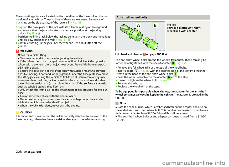
The anti-theft wheel bolts protect the wheels from theft. These can only be loosened or tightened with the use of adapter
B
» Fig. 182 .
›
Remove the full wheel trim or the caps of the wheel bolts.
›
Insert adapter
B
» Fig. 182 with the toothed side all the way into the inner
teeth in the head of the anti-theft wheel bolts
A
.
›
Push the wheel wrench onto the adapter
B
up to the stop.
›
Loosen or tighten the wheel bolt » page 207.
›
Remove the adapter.
›
Replace the wheel trim or the caps.
To be equipped for a possible wheel change, the adapter for the anti-theft
wheel bolts must always be kept in the vehicle. The adapter is stowed in the
tool kit.
Note
■ Note the code number which is embossed both on the adapter and also on
the end of each anti-theft wheel bolt. This number can be used to purchase a
replacement adapter from ŠKODA Original Parts if necessary.■
The anti-theft wheel bolt set and adapter can be purchased from a ŠKODA
Partner.
208Do-it-yourself