tow bar SKODA SUPERB 2009 Owner´s Manual
[x] Cancel search | Manufacturer: SKODA, Model Year: 2009, Model line: SUPERB, Model: SKODA SUPERB 2009Pages: 252, PDF Size: 16.33 MB
Page 216 of 252
›After starting the engine, close the protective cap of the jump-starting point.
Towing the vehicle
Introduction
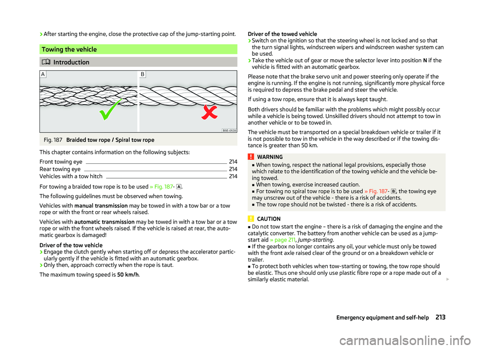
Fig. 187
Braided tow rope / Spiral tow rope
This chapter contains information on the following subjects:
Front towing eye
214
Rear towing eye
214
Vehicles with a tow hitch
214
For towing a braided tow rope is to be used » Fig. 187-
.
The following guidelines must be observed when towing.
Vehicles with manual transmission may be towed in with a tow bar or a tow
rope or with the front or rear wheels raised.
Vehicles with automatic transmission may be towed in with a tow bar or a tow
rope or with the front wheels raised. If the vehicle is raised at rear, the auto-
matic gearbox is damaged!
Driver of the tow vehicle
›
Engage the clutch gently when starting off or depress the accelerator partic-
ularly gently if the vehicle is fitted with an automatic gearbox.
›
Only then, approach correctly when the rope is taut.
The maximum towing speed is 50 km/h.
Driver of the towed vehicle›Switch on the ignition so that the steering wheel is not locked and so that
the turn signal lights, windscreen wipers and windscreen washer system can
be used.›
Take the vehicle out of gear or move the selector lever into position N if the
vehicle is fitted with an automatic gearbox.
Please note that the brake servo unit and power steering only operate if the
engine is running. If the engine is not running, significantly more physical force
is required to depress the brake pedal and steer the vehicle.
If using a tow rope, ensure that it is always kept taught.
Both drivers should be familiar with the problems which might possibly occur while a vehicle is being towed. Unskilled drivers should not attempt to tow in
another vehicle or to be towed in.
The vehicle must be transported on a special breakdown vehicle or trailer if it
is not possible to tow in the vehicle in the way described or if the towing dis-
tance is greater than 50 km.
WARNING■ When towing, respect the national legal provisions, especially those
which relate to the identification of the towing vehicle and the vehicle be-
ing towed.■
When towing, exercise increased caution.
■
For towing no spiral tow rope is to be used » Fig. 187-
, the towing eye
may unscrew out of the vehicle - there is a risk of accidents.
■
The tow rope should not be twisted - there is a risk of accidents.
CAUTION
■ Do not tow start the engine – there is a risk of damaging the engine and the
catalytic converter. The battery from another vehicle can be used as a jump-
start aid » page 211 , Jump-starting .■
If the gearbox no longer contains any oil, your vehicle must only be towed
with the front axle raised clear of the ground or on a breakdown vehicle or
trailer.
■
To protect both vehicles when tow-starting or towing, the tow rope should
be elastic. Thus one should only use plastic fibre rope or a rope made out of a
similarly elastic material.
213Emergency equipment and self-help
Page 217 of 252
■There is always a risk of excessive stresses and damage resulting at the
points to which you attach the tow rope or tow bar when you attempt to tow a
vehicle which is not standing on a paved road.■
Attach the tow rope or the tow bar to the towing eyes » page 214 , Front
towing eye or » page 214 , Rear towing eye to the detachable ball head of the
towing equipment » page 166 .
Note
We recommend using a tow rope from ŠKODA Original Accessories, which is
available from a ŠKODA Partner.
Front towing eye
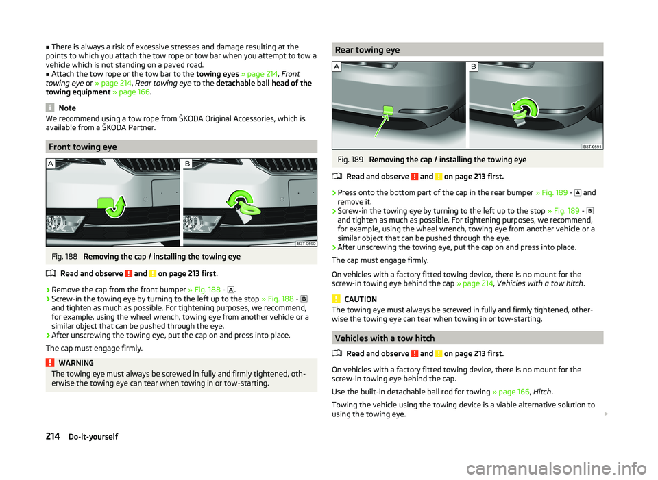
Fig. 188
Removing the cap / installing the towing eye
Read and observe
and on page 213 first.
›
Remove the cap from the front bumper » Fig. 188 -
.
›
Screw-in the towing eye by turning to the left up to the stop
» Fig. 188 -
and tighten as much as possible. For tightening purposes, we recommend,
for example, using the wheel wrench, towing eye from another vehicle or a
similar object that can be pushed through the eye.
›
After unscrewing the towing eye, put the cap on and press into place.
The cap must engage firmly.
WARNINGThe towing eye must always be screwed in fully and firmly tightened, oth-
erwise the towing eye can tear when towing in or tow-starting.Rear towing eyeFig. 189
Removing the cap / installing the towing eye
Read and observe
and on page 213 first.
›
Press onto the bottom part of the cap in the rear bumper » Fig. 189 -
and
remove it.
›
Screw-in the towing eye by turning to the left up to the stop » Fig. 189 -
and tighten as much as possible. For tightening purposes, we recommend,
for example, using the wheel wrench, towing eye from another vehicle or a
similar object that can be pushed through the eye.
›
After unscrewing the towing eye, put the cap on and press into place.
The cap must engage firmly.
On vehicles with a factory fitted towing device, there is no mount for the
screw-in towing eye behind the cap » page 214, Vehicles with a tow hitch .
CAUTION
The towing eye must always be screwed in fully and firmly tightened, other-
wise the towing eye can tear when towing in or tow-starting.
Vehicles with a tow hitch
Read and observe
and on page 213 first.
On vehicles with a factory fitted towing device, there is no mount for the
screw-in towing eye behind the cap.
Use the built-in detachable ball rod for towing » page 166, Hitch .
Towing the vehicle using the towing device is a viable alternative solution to using the towing eye.
214Do-it-yourself
Page 218 of 252
If the towing device is removed completely, it must be replaced with the
standard reinforcement of the rear bumper which is part of the mount for the
towing eye.
If this procedure is not observed, the vehicle may not meet the national legal
provisions.
CAUTION
The detachable ball rod and/or the vehicle can be damaged if an unsuitable
tow bar is used.
Note
The detachable ball rod must always be in the vehicle so that it can be used for
towing, if necessary.
Radio remote control
Introduction
This chapter contains information on the following subjects:
Replacing the battery in the remote control key
215
Synchronising the remote control
215
Replace the battery in the remote control of the auxiliary heater (parking
heater)
216
CAUTION
■ The replacement battery must have the same specification as the original
battery.■
We recommend having faulty batteries replaced by a ŠKODA service partner.
■
Pay attention to the correct polarity when changing the battery.
For the sake of the environment
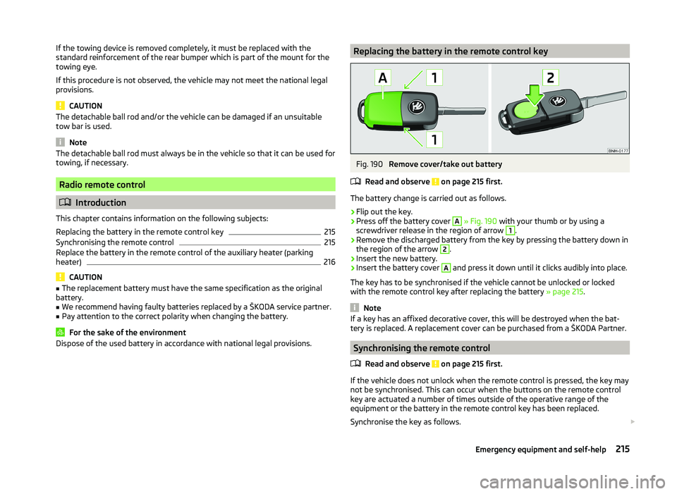
Dispose of the used battery in accordance with national legal provisions.Replacing the battery in the remote control keyFig. 190
Remove cover/take out battery
Read and observe
on page 215 first.
The battery change is carried out as follows.
›
Flip out the key.
›
Press off the battery cover
A
» Fig. 190 with your thumb or by using a
screwdriver release in the region of arrow
1
.
›
Remove the discharged battery from the key by pressing the battery down in
the region of the arrow
2
.
›
Insert the new battery.
›
Insert the battery cover
A
and press it down until it clicks audibly into place.
The key has to be synchronised if the vehicle cannot be unlocked or locked
with the remote control key after replacing the battery » page 215.
Note
If a key has an affixed decorative cover, this will be destroyed when the bat-
tery is replaced. A replacement cover can be purchased from a ŠKODA Partner.
Synchronising the remote control
Read and observe
on page 215 first.
If the vehicle does not unlock when the remote control is pressed, the key maynot be synchronised. This can occur when the buttons on the remote control
key are actuated a number of times outside of the operative range of the
equipment or the battery in the remote control key has been replaced.
Synchronise the key as follows.
215Emergency equipment and self-help
Page 231 of 252
Technical data
Technical data
Vehicle data
Introduction
This chapter contains information on the following subjects:
Vehicle identification data
228
Operating weight and payload
229
Measurement of fuel consumption and CO 2 emissions according to ECE
Regulations and EU Directives
229
Dimensions
230
Vehicle-specific information depending on engine type
231
Multi-purpose vehicles (AF)
235
The details given in the vehicle's technical documentation always take prece-
dence over the details in the Owner's Manual.
The listed performance values were determined without performance-reduc- ing equipment, e.g. air conditioning system.
Vehicle identification data
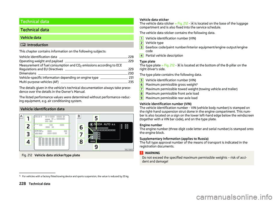
Fig. 212
Vehicle data sticker/type plate
Vehicle data sticker
The vehicle data sticker » Fig. 212 - is located on the base of the luggage
compartment and is also fixed into the service schedule.
The vehicle data sticker contains the following data. Vehicle identification number (VIN)
Vehicle type
Gearbox code/paint number/interior equipment/engine output/engine
code
Partial vehicle description
Type plate
The type plate » Fig. 212 -
is located at the bottom of the B-pillar on the
right driver's side.
The type plate contains the following data. Vehicle identification number (VIN)
Maximum permissible gross weight 1)
Maximum permissible towed weight (towing vehicle and trailer)
Maximum permissible front axle load
Maximum permissible rear axle load
Vehicle identification number (VIN)
The vehicle identification number - VIN (vehicle body number) is stamped on
the right-hand suspension strut dome in the engine compartment. This num- ber is also located on a sign on the lower left-hand edge below the windscreen
(together with a VIN bar code), and on the type plate.
Engine number
The engine number (three-digit code letter and serial number) is stamped onto
the engine block.
Supplementary Information (applies to Russia)
The full type approval number of the means of transport is indicated in the
registration documents.WARNINGDo not exceed the specified maximum permissible weights – risk of acci-
dent and damage!1234567891)
For vehicles with a factory fitted towing device and sports suspension, the value is reduced by 25 kg.
228Technical data
Page 232 of 252

Operating weight and payload
Operating weight
This value represents the minimum operating weight without additional
weight-increasing equipment such as air conditioning system, spare wheel, or
trailer hitch.
The specified operating weight is for orientation purposes only.
The operating weight also contains the weight of the driver (75 kg), the weight
of the operating fluids, the tool kit, and a fuel tank filled to 90 % capacity.
Operating weight of the vehicle » page 231, Vehicle-specific information de-
pending on engine type .
Payload
It is possible to calculate the approximate maximum payload from the differ-
ence between the permissible total weight and the operating weight.
The payload consists of the following weights.
› The weight of the passengers.
› The weight of all items of luggage and other loads.
› The weight of the roof, including the roof rack system.
› The weight of the equipment that is excluded from the operating weight.
› Trailer drawbar load when towing a trailer (max. 80 kg).
Note
If required, you can find out the precise weight of your vehicle at a specialist
garage.
Measurement of fuel consumption and CO 2 emissions according to
ECE Regulations and EU Directives
The data on fuel consumption and CO 2 emissions were not available at the
time of going to press.
The data on fuel consumption and CO 2 emissions are given on the ŠKODA
websites or in the sales and technical vehicle documentation.
The measurement of the intra-urban cycle begins with a cold start of the en-
gine. Afterwards urban driving is simulated.
In the extra-urban driving cycle, the vehicle is accelerated and decelerated in
all gears, corresponding to daily routine driving conditions. The driving speed
varies between 0 and 120 km/h.
The calculation of the combined fuel consumption considers a weighting of
about 37 % for the intra-urban cycle and 63 % for the extra-urban cycle.
Note
■ The fuel consumption and emission levels given on the ŠKODA websites or in
the commercial and technical vehicle documentation have been established in
accordance with rules and under conditions that are set out by legal or techni-
cal rules for the determination of operational and technical data of motor vehi-
cles.■
Depending on the extent of the equipment, the driving style, traffic condi-
tions, weather influences and vehicle condition, consumption values can in
practice result in fuel economy figures in the use of the vehicle that differ from
the fuel consumption values listed on the ŠKODA websites or in the commer-
cial and technical vehicle documentation.
229Technical data