tow SKODA SUPERB 2009 Owner´s Manual
[x] Cancel search | Manufacturer: SKODA, Model Year: 2009, Model line: SUPERB, Model: SKODA SUPERB 2009Pages: 252, PDF Size: 16.33 MB
Page 105 of 252
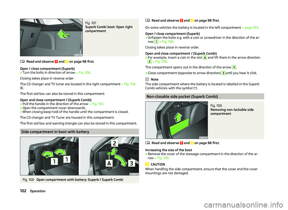
Fig. 107
Superb Combi boot: Open right
compartment
Read and observe and on page 98 first.
Open / close compartment (Superb)
›
Turn the bolts in direction of arrow » Fig. 106.
Closing takes place in reverse order.
The CD changer and TV tuner are located in the right compartment » Fig. 106
.
The first-aid box can also be stored in this compartment.
Open and close compartment / (Superb Combi)
›
Pull the handle in the direction of the arrow » Fig. 107.
›
Open the compartment cover downwards.
›
When closing keep hold of the handle until the compartment is closed.
The CD changer and TV Tuner are housed in this compartment.
The first-aid box and warning triangle can also be stored in this compartment.
Side compartment in boot with battery
Fig. 108
Open compartment with battery: Superb / Superb Combi
Read and observe and on page 98 first.
On some vehicles the battery is located in the left compartment » page 193.
Open / close compartment (Superb)
›
Unfasten the bolts e.g. with a coin or screwdriver in the direction of the ar-
row
1
» Fig. 108 .
Closing takes place in reverse order.
Open and close compartment / (Superb Combi)
›
For example, insert a coin in the slot
A
and lift them in the arrow direction
2
» Fig. 108 .
The compartment opens out in the direction of the arrow
3
.
›
Close compartment (opposite to arrow direction)
3
until you hear it click.
Note
The side compartment where the battery is located is labelled in the Superb
Combi vehicles with the symbol .
Non-closable side pocket (Superb Combi)
Fig. 109
Removing non-lockable side
compartment
Read and observe and on page 98 first.
Increasing the size of the boot
›
Remove the cover of the stowage compartment in the direction of the ar-
row » Fig. 109 .
CAUTION
When handling the side compartment, ensure that the cover and the cover
mountings are not damaged.102Operation
Page 107 of 252
›Insert the cover for the rechargeable batteries and press it down until it
clicks into place.
CAUTION
■ We recommend having faulty rechargeable batteries replaced by a ŠKODA
service partner. If the lamp is not correctly opened, it can be damaged.■
Pay attention to the correct polarity when changing the rechargeable batter-
ies.
■
The replacement rechargeable batteries must have the same specification as
the original rechargeable batteries. If other types of rechargeable batteries are
used, the power output can be reduced or it can lead to a malfunction of the
lamp.
For the sake of the environment
Dispose of used rechargeable batteries in accordance with national legal provi- sions.
Variable loading floor in the luggage compartment (Estate)
Introduction
This chapter contains information on the following subjects:
Dividing the luggage compartment
104
Remove variable loading floor
104
The variable loading floor makes handling of bulky items of luggage easier.
CAUTION
The maximum permissible load of the variable loading floor is 75 kg.
Note
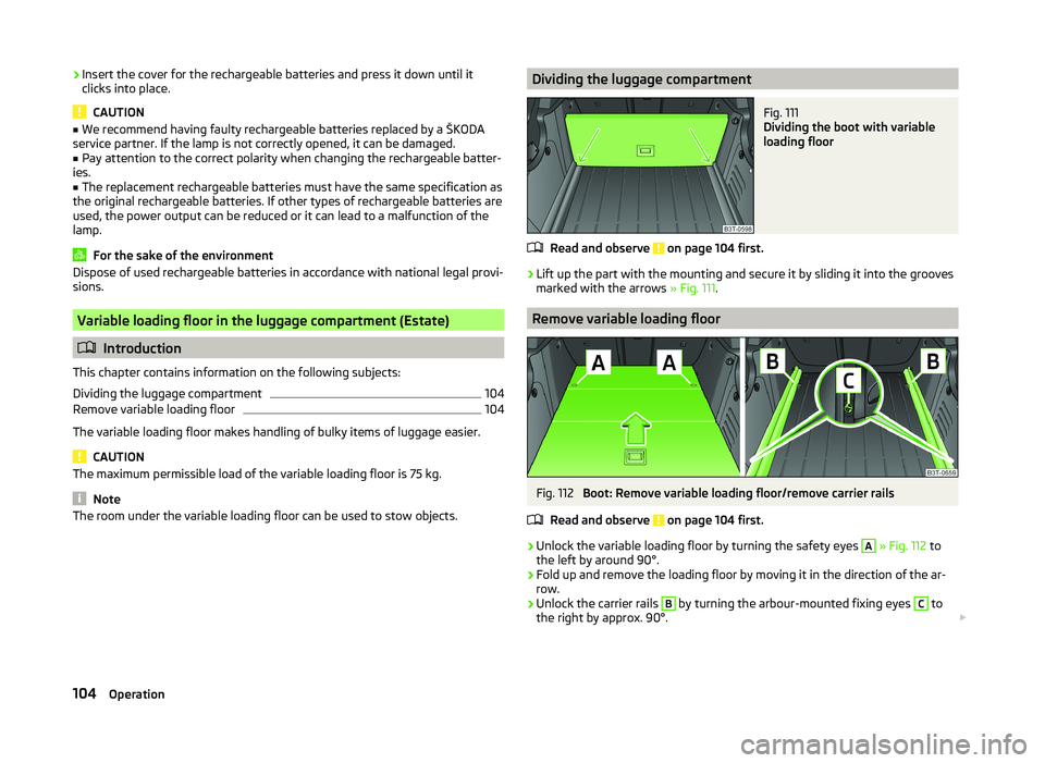
The room under the variable loading floor can be used to stow objects.Dividing the luggage compartmentFig. 111
Dividing the boot with variable
loading floor
Read and observe on page 104 first.
›
Lift up the part with the mounting and secure it by sliding it into the grooves
marked with the arrows » Fig. 111.
Remove variable loading floor
Fig. 112
Boot: Remove variable loading floor/remove carrier rails
Read and observe
on page 104 first.
›
Unlock the variable loading floor by turning the safety eyes
A
» Fig. 112 to
the left by around 90°.
›
Fold up and remove the loading floor by moving it in the direction of the ar-
row.
›
Unlock the carrier rails
B
by turning the arbour-mounted fixing eyes
C
to
the right by approx. 90°.
104Operation
Page 108 of 252
WARNINGEnsure that the carrier rails and variable loading floor are correctly fastened
when installing the variable loading floor. If this is not the case, there is a
risk of injury for the occupants.
Extending variable loading floor with integrated aluminium rails
and fastening elements (Superb Combi)
Introduction
This chapter contains information on the following subjects:
Partial extension of variable load floor
105
Divide boot
105
Fit and remove variable loading floor
106
Fixing set
106
Movable lashing eyes
107
The variable loading floor makes handling of bulky items of luggage easier.
CAUTION
The maximum permissible load of the variable loading floor is 75 kg.
Note
The space below the variable loading floor can be used for stowing objects, for
example the fastening elements, removed foldable boot cover, etc.
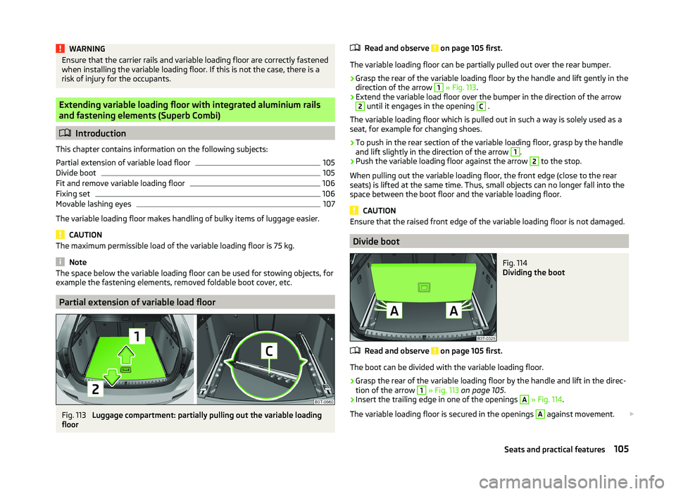
Partial extension of variable load floor
Fig. 113
Luggage compartment: partially pulling out the variable loading
floor
Read and observe on page 105 first.
The variable loading floor can be partially pulled out over the rear bumper.
›
Grasp the rear of the variable loading floor by the handle and lift gently in the
direction of the arrow
1
» Fig. 113 .
›
Extend the variable load floor over the bumper in the direction of the arrow
2
until it engages in the opening
C
.
The variable loading floor which is pulled out in such a way is solely used as a
seat, for example for changing shoes.
›
To push in the rear section of the variable loading floor, grasp by the handle
and lift slightly in the direction of the arrow
1
.
›
Push the variable loading floor against the arrow
2
to the stop.
When pulling out the variable loading floor, the front edge (close to the rear
seats) is lifted at the same time. Thus, small objects can no longer fall into the
space between the boot floor and the variable loading floor.
CAUTION
Ensure that the raised front edge of the variable loading floor is not damaged.
Divide boot
Fig. 114
Dividing the boot
Read and observe on page 105 first.
The boot can be divided with the variable loading floor.
›
Grasp the rear of the variable loading floor by the handle and lift in the direc-
tion of the arrow
1
» Fig. 113 on page 105 .
›
Insert the trailing edge in one of the openings
A
» Fig. 114 .
The variable loading floor is secured in the openings
A
against movement.
105Seats and practical features
Page 141 of 252
Driving
Starting off and Driving
Starting and stopping the engine using the key
Introduction
This chapter contains information on the following subjects:
Electronic immobilizer
139
Ignition Switch
139
Starting the engine
139
Stopping the engine
140
Starting and stopping the engine on vehicles with the KESSY sys-
tem » page 140 .
The engine can only be started using a correctly coded original key.
The engine running noises may louder at first be louder for a short time after
starting the cold engine. This is quite normal and is not an operating problem.
WARNING■ When the vehicle is travelling with the engine off, the ignition key must
always be in position 2 » Fig. 134 on page 139 (ignition switched on). This
position is confirmed by the appearance of certain indicator lamps in the in-
strument cluster. ■If the key is not in position 2,
it could unexpectedly lock the steering -
danger of accident!
■
Only pull the ignition key from the ignition lock when the vehicle has
come to a complete stop (by applying the handbrake). Otherwise, the steer-
ing could be blocked – risk of accident!
■
Never leave the key in the vehicle when you exit the vehicle. Unauthor-
ized persons, such as children, for example, could lock the car, turn on the
ignition or start the engine - there is a danger of injury and accidents!
■
Never leave the vehicle unattended with the engine running - there is
risk of accident, damage or theft!
■
Never switch off the engine before the vehicle is stationary – risk of acci-
dent!
WARNING■ Never leave the engine running in unventilated or closed rooms. The en-
gine's exhaust gases also contain the odourless and colourless carbon
monoxide, a poisonous gas – risk of death. ■ Carbon monoxide can cause unconsciousness and death.■
Do not leave any items (e.g. cleaning cloths or tools) in the engine com-
partment. This presents a fire hazard and the risk of engine damage.
■
Never cover the engine with additional insulation material (e.g. with a
cover) – risk of fire!
CAUTION
■ The starter must only be operated when the engine is not running and the
vehicle is at a standstill. The starter or engine can be damaged if the starter is
activated when the engine is running 3
» Fig. 134 on page 139 .
■
Do not tow start the engine – there is a risk of damaging the engine and the
catalytic converter. The battery from another vehicle can be used as a jump-
start aid » page 211 , Jump-starting .
CAUTION
■
Avoid high engine revolutions, full throttle and high engine loads before the
engine has reached its operating temperature – risk of damaging the engine!■
Do not switch the engine off immediately at the end of your journey after the
engine has been operated over a prolonged period at high loads but leave it to
run at an idling speed for about 1 minute. This prevents any possible accumula-
tion of heat when the engine is switched off.
For the sake of the environment
Do not warm up the engine while the vehicle is stationary. If possible, start
your journey as soon as the engine has started. Through this the engine rea-
ches its operating temperature more rapidly and the pollutant emissions are
lower.
Note
After switching off the ignition, the radiator fan can intermittently continue to
operate for approx. 10 minutes.138Driving
Page 143 of 252
Vehicles with automatic transmission1)
The engine will not start if the brake pedal is not depressed.
The following message is shown in the instrument cluster display. Depress the brake to start.
BRAKE
CAUTION
■ If the engine does not start-up after a second attempt, one of the following
fuses may be defective. ■ Petrol engine - fuse for the electric fuel pump.
■ Diesel engine - fuse for the control unit for glow plugs or glow plug relay
and fuel pump.■
Check the fuse and replace if necessary » page 220, or seek assistance from
a specialist garage.
Stopping the engine
Read and observe
and on page 138 first.
Switch off the engine by turning the ignition key to position
1
» Fig. 134 on
page 139 .
For vehicles with automatic transmission, the ignition key can only be removed
if the selector lever is in position P.
Starting and stopping the engine - KESSY
Introduction
This chapter contains information on the following subjects:
Steering lock / unlock
141
Ignition on/off
141
Starting the engine
142
Switching off the engine
142
Emergency start-up of the engine
142
Emergency ignition shutoff system
143The KESSY system (Keyless Entry Exit System, hereinafter referred to only as
system) allows the switching on or switching off of the ignition and starting or
stopping of the engine without the active use of the key.
A key must be in the vehicle to unlock the steering, switch on the ignition and
start the vehicle. When travelling the key must be in the vehicle.
The engine running noises may louder at first be louder for a short time after starting the cold engine. This is quite normal and is not an operating problem.WARNING■ Never leave the key in the vehicle when you exit the vehicle. Unauthor-
ized persons, such as children, for example, could lock the car, turn on the
ignition or start the engine - there is a danger of injury and accidents!■
Never leave the vehicle unattended with the engine running - there is a
risk of theft etc!
■
Never switch off the engine before the vehicle is stationary – risk of acci-
dent!
WARNING■ Never leave the engine running in unventilated or closed rooms. The en-
gine's exhaust gases also contain the odourless and colourless carbon
monoxide, a poisonous gas – risk of death. ■ Carbon monoxide can cause unconsciousness and death.
CAUTION
■The system can recognize the valid key, even if it has been forgotten, for ex-
ample, in the front of the vehicle roof D » Fig. 34 on page 53 - There is danger
of loss or damage to the key! It is therefore not always necessary to know
where the key is.■
The starter must only be operated when the engine is not running and the
vehicle is at a standstill. The starter or engine may be damaged if the starter is
activated when the engine is running.
■
Do not tow start the engine – there is a risk of damaging the engine and the
catalytic converter. The battery from another vehicle can be used as a jump-
start aid » page 211 , Jump-starting .
1)
Applies to vehicles with START STOP system.
140Driving
Page 146 of 252
Emergency ignition shutoff systemRead and observe
and on page 140 first.
The ignition can be turned off in an emergency even when travelling at a
speed of more than 2 km / hr.
›
Press the starter button » Fig. 135 on page 141 for longer than 1 second or
twice within 1 second.
After emergency stop of the ignition, the steering is unlocked.
Brakes
Introduction
This chapter contains information on the following subjects:
Information on braking
143
Handbrake
144WARNING■ Greater physical effort is required for braking when the engine is switch-
ed off – risk of accident!■
The clutch pedal must be depressed when braking on a vehicle with man-
ual transmission, when the vehicle is in gear and at low revs. Otherwise,
the function of the brake booster may be impaired – risk of accident!
■
When leaving the vehicle, never leave persons who might, for example,
release the handbrake or take the vehicle out of gear unattended in the ve-
hicle. The vehicle could then start to move – risk of accident!
WARNINGIn the case of damage to the standard fitted front spoiler or if retrofitting
another front spoiler, hub caps etc. » page 173, Services, modifications and
technical alterations , make sure that the air supply to the front brakes is
not affected. The front brakes may overheat, which can have a negative im-
pact on the functioning of the braking system – there is a risk of an acci-
dent!CAUTION■ Observe the recommendations on the new brake pads » page 149.■Never let the brakes slip with light pressure on the pedal if braking is not
necessary. This causes the brakes to overheat and can also result in a longer
braking distance and excessive wear.
Information on braking
Read and observe
and on page 143 first.
If the brakes are applied in full and the control unit for the braking system con-siders the situation to be dangerous for the following traffic, the brake light
flashes automatically.
After the speed was reduced below around 10 km/h or the vehicle was stop-
ped, the brake light stops flashing and the hazard warning light system
switches on. The hazard warning light system is switched off automatically af- ter accelerating or driving off again.
Before travelling a long distance down a steep gradient, reduce speed and
shift into the next lowest gear. As a result, the braking effect of the engine will
be used, reducing the load on the brakes. Any additional braking should be
completed intermittently, not continuously.
Wear-and-tear
The wear of the brake pads is dependent on the operating conditions and driv- ing style.
The brake pads wear more quickly if a lot of journeys are completed in towns
and over short distances or if a very sporty style of driving is adopted.
Under these severe conditions , the thickness of the brake pads must also be
checked by a specialist garage between services.
Wet roads or road salt
The performance of the brakes can be delayed as the brake discs and brake
pads may be moist or have a coating of ice or layer of salt on them in winter.
The brakes are cleaned and dried by applying the brakes several times.
Corrosion
Corrosion on the brake discs and dirt on the brake pads occur if the vehicle has
been parked for a long period and if you do not make much use of the braking
system. The brakes are cleaned by applying the brakes several times.
143Starting off and Driving
Page 150 of 252
Switching to manual shifting›Push the gear selector from position D towards the right, or left in a right-
hand drive vehicle.
Shifting up gears›
Press the selector lever forwards
+
» Fig. 141 .
›
Pull the right-hand paddle +
» Fig. 141 briefly towards the steering wheel.
Shifting down gears
›
Press the selector lever backwards
-
» Fig. 141 .
›
Pull the left-hand paddle -
» Fig. 141 briefly towards the steering wheel.
Temporarily switching to manual gear shifting in mode D or S
›
Pull one of the -/+ paddles
» Fig. 141 briefly towards the steering wheel .
Manual gear shifting is deactivated if more than 1 minute passes after either of
the -
/+ paddles was pulled. The temporary switch to manual gear shifting can
also be deactivated by pulling the right-hand + paddle towards the steering
wheel for more than 1 second.
When accelerating, the gearbox automatically shifts up into the higher gear
just before the maximum permissible engine speed is reached.
If a lower gear is selected, the gearbox does not shift down until there is no risk of the engine over revving.
Note
It may be beneficial, for example, when travelling downhill, to use manual
shifting of gears. Shifting to a lower gear reduces the load on the brakes and
hence brake wear » page 143.
Starting off and driving
Read and observe
and on page 145 first.
Starting off
›
Start the engine.
›
Firmly depress and hold the brake pedal.
›
Press the lock button in the direction of the arrow » Fig. 140 on page 146 and
keep pressing.
›
Move the selector lever into the desired position » page 145 and then release
the lock button.
› Release the brake pedal and accelerate.
Stop›
Fully depress and hold the brake pedal and bring the vehicle to a stop.
›
Keep holding the brake pedal until driving is resumed.
The selector lever position N does not have to be selected when stopping for a
short time, such as at a cross roads.
Parking
›
Fully depress and hold the brake pedal and bring the vehicle to a stop.
›
Firmly apply the handbrake.
›
Press the lock button in the direction of the arrow » Fig. 140 on page 146 and
keep pressing.
›
Move the selector lever into the position P and then release the locking but-
ton.
Launch control 1)
The launch control function allows the vehicle in mode S or Tiptronic to reach
its maximum acceleration when starting off.
›
Disable the ASR » page 154, Brake assist systems .
›
START STOP deactivate » page 164.
›
Fully depress and hold the brake pedal with your left foot.
›
Fully depress the accelerator pedal with your right foot.
›
Release the brake pedal.
The vehicle starts off with maximum acceleration.
Reactivate the ASR and START STOP when the desired speed has been
reached.
Kickdown
The kickdown function allows you to achieve maximum acceleration by your
vehicle while driving.
When the accelerator pedal is fully depressed, the kickdown function is activa-
ted in any forward driving mode.
The gearbox shifts down one or more gears depending on the vehicle speed
and engine speed, and the vehicle accelerates.
The gearbox does not shift up into the highest gear until the engine has
reached its maximum revolutions for this gear range.
1)
This function is only valid for some engines.
147Starting off and Driving
Page 151 of 252
WARNINGRapid acceleration, particularly on slippery roads, can lead to loss of control
of the vehicle – there is a risk of an accident.
Malfunction
Read and observe
and on page 145 first.
Emergency programme
The transmission switches to the emergency programme if there is a fault in
the automatic gearbox system.
Indications of an activated emergency programme include the following:
› Only certain gears are selected.
› Reverse gear
R cannot be used.
› Shifting gears in Tiptronic mode is not possible.
Gearbox overheating
The gearbox may, for example, become too hot due to frequent repeated
starting or stop-and-go traffic. Overheating is indicated by the warning
light » page 33 ,
Clutches of the automatic DSG gearbox are too hot
.
Defective selector lever lock
If the selector lever lock is defective or its power supply is interrupted (e.g. dis-
charged vehicle battery, faulty fuse), the selector lever can no longer be moved
out of position P in the normal manner, and the vehicle can no longer be driv-
en. The selector lever must be emergency released » page 217.
Note
Visit a specialist workshop if the gearbox has switched to the emergency pro-
gramme.
Running in
Introduction
This chapter contains information on the following subjects:
New engine
148
New tyres
149
New brake pads
149New engine
The engine has to be run in during the first 1 500 kilometres.
Up to 1,000 kilometres›
Do not drive faster than 3/4 of the maximum speed of the gear in use, which
means 3/4 of the maximum permissible engine speed.
›
No full throttle.
›
Avoid high engine speeds.
›
Do not tow a trailer.
From 1,000 up to 1,500 kilometres
Gradually increase the power output of the engine up to the full speed of the
gear engaged, which means up to the maximum permissible engine speed.
The red scale on the rev counter indicates the range in which the system be-
gins to limit the engine speed.
During the first operating hours the engine has higher internal friction than
later until all of the moving parts have harmonized. The driving style which you
adopt during the first approx.1 500 kilometres plays a decisive part in the suc-
cess of running in your car.
Never drive at unnecessarily high engine speeds even after the running in pe-
riod.
On vehicles fitted with a manual gearbox, at the very latest shift up into the
next gear when the red area is reached. Observe the recommended
gear » page 43 , Gear recommendation . Very high engine speeds when acceler-
ating (accelerator) are automatically restricted »
.
In vehicles with manual transmission, do not drive at unnecessarily low engine
speeds. Shift down a gear when the engine is no longer running smoothly. Ob-
serve the recommended gear » page 43, Gear recommendation .
CAUTION
■
The engine is not protected from excessive engine revs caused by shifting
down at the wrong time. This can result in a sudden increase in revs beyond
the permissible maximum rpm and hence engine damage.■
Never rev up a cold engine when the vehicle is stationary or when driving in
individual gears.
For the sake of the environment
Do not drive at unnecessarily high engine speeds. Shifting up sooner helps
save fuel, reduces engine noise and protects the environment.148Driving
Page 154 of 252
Always ensure the tyre inflation pressure is correct » page 198. If the pressure
is too low, the tyres will have to overcome a higher rolling resistance. This will
not only increase fuel consumption but also tyre wear and the driving behav-
iour will worsen.
Always check the tyre inflation pressure when the tyres are cold.
Avoiding unnecessary ballast
Read and observe
on page 149 first.
Transporting ballast costs fuel.
Each kilogramme of weight increases the fuel consumption. Therefore we rec-
ommend carrying no unnecessary weight.
It is particularly in town traffic, when one is accelerating quite often, that the
vehicle weight will have a significant effect upon the fuel consumption. A rule
of thumb here is that an increase in weight of 100 kilograms will cause an in-
crease in fuel consumption of about 1 litre/100 kilometres.
At a speed of 100 - 120 km/h, a vehicle fitted with a roof rack cross member
without a load will use about 10 % more fuel than normal due to the increased
aerodynamic drag.
Regular maintenance
Read and observe
on page 149 first.
A poorly tuned engine uses an unnecessarily high amount of fuel.
By having your vehicle regularly maintained by a specialist garage, you create
the conditions needed for economical driving. The maintenance state of your
vehicle has a positive effect on traffic safety and value retention
A poorly tuned engine can result in a fuel consumption which is 10 % higher than normal.
Check the oil level at regular intervals, e.g. when filling up. Oil consumption is
dependent to a considerable extent on the load and speed of the engine. Oil
consumption could be as high as 0.5 litres/1 000 km depending on your style
of driving.
It is quite normal that a new engine has higher oil consumption at first, and
reaches its lowest level only after a certain running in time. The oil consump-
tion of a new vehicle can therefore only be correctly assessed after driving
about 5,000 km.
For the sake of the environment■ Additional improvements to the fuel economy can be made by using synthet-
ic low viscosity oils.■
Regularly check the ground under the vehicle. Have your vehicle inspected by
a specialist garage if you find any stains caused by oil or other fluids on the
ground.
Note
We recommend that your vehicle be serviced on a regular basis by a ŠKODA
service partner.
Saving electrical energy
Read and observe
on page 149 first.
When the engine is running, the alternator generates and supplies electricalpower. If more electrical components of the electrical system are switched on,
more fuel is needed to operate the alternator. We therefore recommend
switching off electrical components if these are no longer required.
Environmental compatibility
Read and observe
on page 149 first.
Environmental protection has played a major role in the design, material selec-
tion and production of your new ŠKODA. Particular emphasis has been placed
on the following points.
Design measures › Joints designed to be easily detached.
› Simplified disassembly due to the modular structure system.
› Improved purity of different classes of materials.
› Identification of all plastic parts in accordance with VDA Recommendation
260.
› Reduced fuel consumption and exhaust emission CO
2.
› Minimum fuel leakage during accidents.
› Reduced noise.
Choice of materials
› Extensive use of recyclable material.
› Air conditioning filled with CFC-free refrigerant.
› No cadmium.
151Starting off and Driving
Page 160 of 252
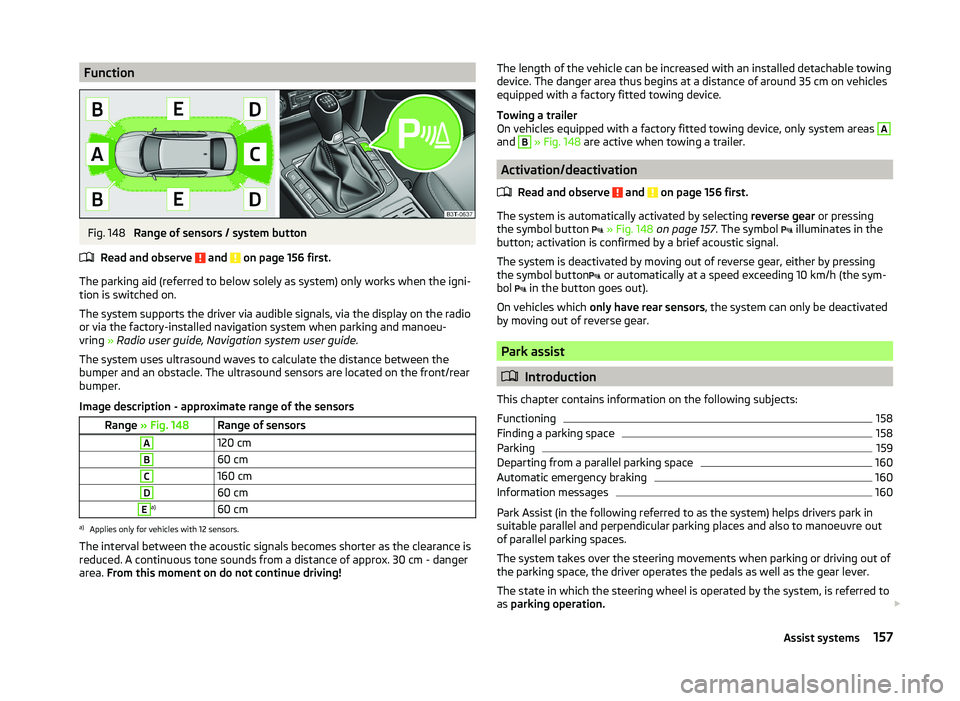
FunctionFig. 148
Range of sensors / system button
Read and observe
and on page 156 first.
The parking aid (referred to below solely as system) only works when the igni-
tion is switched on.
The system supports the driver via audible signals, via the display on the radio
or via the factory-installed navigation system when parking and manoeu-
vring » Radio user guide, Navigation system user guide.
The system uses ultrasound waves to calculate the distance between the
bumper and an obstacle. The ultrasound sensors are located on the front/rear
bumper.
Image description - approximate range of the sensors
Range » Fig. 148Range of sensorsA120 cmB60 cmC160 cmD60 cmEa)60 cma)
Applies only for vehicles with 12 sensors.
The interval between the acoustic signals becomes shorter as the clearance is
reduced. A continuous tone sounds from a distance of approx. 30 cm - danger
area. From this moment on do not continue driving!
The length of the vehicle can be increased with an installed detachable towing
device. The danger area thus begins at a distance of around 35 cm on vehicles equipped with a factory fitted towing device.
Towing a trailer
On vehicles equipped with a factory fitted towing device, only system areas A
and
B
» Fig. 148 are active when towing a trailer.
Activation/deactivation
Read and observe
and on page 156 first.
The system is automatically activated by selecting reverse gear or pressing
the symbol button
» Fig. 148 on page 157 . The symbol
illuminates in the
button; activation is confirmed by a brief acoustic signal.
The system is deactivated by moving out of reverse gear, either by pressing the symbol button or automatically at a speed exceeding 10 km/h (the sym-
bol in the button goes out).
On vehicles which only have rear sensors , the system can only be deactivated
by moving out of reverse gear.
Park assist
Introduction
This chapter contains information on the following subjects:
Functioning
158
Finding a parking space
158
Parking
159
Departing from a parallel parking space
160
Automatic emergency braking
160
Information messages
160
Park Assist (in the following referred to as the system) helps drivers park in
suitable parallel and perpendicular parking places and also to manoeuvre out
of parallel parking spaces.
The system takes over the steering movements when parking or driving out of
the parking space, the driver operates the pedals as well as the gear lever.
The state in which the steering wheel is operated by the system, is referred to
as parking operation.
157Assist systems