lock SKODA SUPERB 2009 Owner´s Manual
[x] Cancel search | Manufacturer: SKODA, Model Year: 2009, Model line: SUPERB, Model: SKODA SUPERB 2009Pages: 252, PDF Size: 16.33 MB
Page 107 of 252
›Insert the cover for the rechargeable batteries and press it down until it
clicks into place.
CAUTION
■ We recommend having faulty rechargeable batteries replaced by a ŠKODA
service partner. If the lamp is not correctly opened, it can be damaged.■
Pay attention to the correct polarity when changing the rechargeable batter-
ies.
■
The replacement rechargeable batteries must have the same specification as
the original rechargeable batteries. If other types of rechargeable batteries are
used, the power output can be reduced or it can lead to a malfunction of the
lamp.
For the sake of the environment
Dispose of used rechargeable batteries in accordance with national legal provi- sions.
Variable loading floor in the luggage compartment (Estate)
Introduction
This chapter contains information on the following subjects:
Dividing the luggage compartment
104
Remove variable loading floor
104
The variable loading floor makes handling of bulky items of luggage easier.
CAUTION
The maximum permissible load of the variable loading floor is 75 kg.
Note
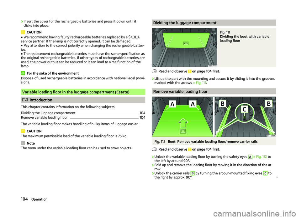
The room under the variable loading floor can be used to stow objects.Dividing the luggage compartmentFig. 111
Dividing the boot with variable
loading floor
Read and observe on page 104 first.
›
Lift up the part with the mounting and secure it by sliding it into the grooves
marked with the arrows » Fig. 111.
Remove variable loading floor
Fig. 112
Boot: Remove variable loading floor/remove carrier rails
Read and observe
on page 104 first.
›
Unlock the variable loading floor by turning the safety eyes
A
» Fig. 112 to
the left by around 90°.
›
Fold up and remove the loading floor by moving it in the direction of the ar-
row.
›
Unlock the carrier rails
B
by turning the arbour-mounted fixing eyes
C
to
the right by approx. 90°.
104Operation
Page 109 of 252

The variable loading floor can be pulled out a little more before dividing the
boot with the variable loading floor » page 105. This enlarges the space be-
tween the rear seats and the separation.
CAUTION
Ensure that the raised front edge of the variable loading floor is not damaged.
Fit and remove variable loading floor
Fig. 115
Luggage compartment: fold up variable loading floor
Fig. 116
Luggage compartment: variable loading floor
Read and observe
on page 105 first.
The variable loading floor can be removed and reinstalled, if necessary.
Removing
›
Grasp the rear part of the floor by the handle, raise it slightly in the direction
of the arrow
1
» Fig. 115 and pull it out over the bumper in the direction of
the arrow
2
until it engages in the opening
C
» Fig. 116 .
›Fold up the loading floor by moving it in the direction of the arrow3» Fig. 115
.›
Press the safety buttons
A
» Fig. 116 and remove the floor.
Fitting
›
Fold up the floor and place it on the carrier rails.
›
Push the floor forwards until it engages in the openings
B
in the carrier
rails » Fig. 116 .
›
Carefully press in the vicinity of the openings
C
on the floor until it clicks in-
to place, if necessary press the safety buttons
A
.
WARNINGEnsure the variable loading floor is attached correctly during installation. If
this is not the case, there is a risk of injury for the occupants.
Fixing set
Fig. 117
Telescopic pole and tensioning strap
Read and observe
on page 105 first.
The fixing set can be used for dividing the boot or for securing the objects
which are being transported.
Telescopic pole
›
Insert the holders for the telescopic pole into the left and right openings of
the carrier rails.
›
Press the top part of the holder in the direction of the arrow
1
» Fig. 117 and
simultaneously push in the desired position in the direction of the arrow
2
.
›
Ensure that the holder is correctly locked in place.
106Operation
Page 110 of 252
Tensioning strap›Insert the tensioning strap holders into the opening on the left or right carri-
er rail.›
Press the holder in the direction of the arrow
3
» Fig. 117 and simultaneous-
ly push in the desired position in the direction of the arrow
4
.
›
Ensure that the holder is correctly locked in place.
›
Place the object that is to be secured behind the tensioning strap.
›
Press the button
5
on the top side of the holder and tighten the strap.
WARNINGThe objects in the boot must be firmly secured with the fixing set so that
they cannot move freely and uncontrollably and to prevent damage to ob-
jects or injuries to occupants.
Note
■ Do not use the fixing set to secure objects that might damage the fixing set.■The tensioning strap can also be fully reeled up by pressing the button5
» Fig. 117 .
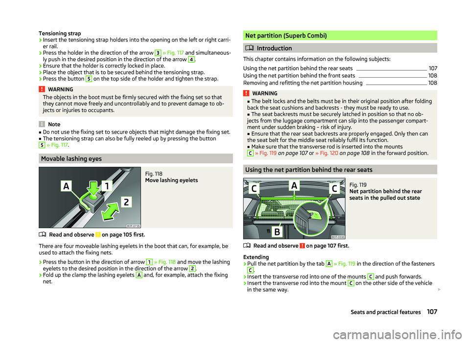
Movable lashing eyes
Fig. 118
Move lashing eyelets
Read and observe on page 105 first.
There are four moveable lashing eyelets in the boot that can, for example, be
used to attach the fixing nets.
›
Press the button in the direction of arrow
1
» Fig. 118 and move the lashing
eyelets to the desired position in the direction of the arrow
2
.
›
Fold up the clamp the lashing eyelets
A
and, for example, attach the fixing
net.
Net partition (Superb Combi)
Introduction
This chapter contains information on the following subjects:
Using the net partition behind the rear seats
107
Using the net partition behind the front seats
108
Removing and refitting the net partition housing
108WARNING■ The belt locks and the belts must be in their original position after folding
back the seat cushions and backrests - they must be ready to use.■
The seat backrests must be securely latched in position so that no ob-
jects from the luggage compartment can slip into the passenger compart-
ment under sudden braking – risk of injury.
■
Ensure that the rear seat backrests are properly engaged. Only then can
the seat belt for the middle seat reliably fulfil its function.
■
Make sure that the transverse rod is inserted into the mounts
C
» Fig. 119 on page 107 or » Fig. 120 on page 108 in the forward position.
Using the net partition behind the rear seats
Fig. 119
Net partition behind the rear
seats in the pulled out state
Read and observe on page 107 first.
Extending
›
Pull the net partition by the tab
A
» Fig. 119 in the direction of the fasteners
C
.
›
Insert the transverse rod into one of the mounts
C
and push forwards.
›
Insert the transverse rod into the mount
C
on the other side of the vehicle
in the same way.
107Seats and practical features
Page 122 of 252

WARNING■The auxiliary heating must never be operated in closed rooms (e.g. garag-
es) – risk of poisoning!■
The auxiliary heating must not be allowed to run during refuelling – risk
of fire.
■
The exhaust pipe of the auxiliary heating is located on the underside of
the vehicle. If you want to use the heater, then the car should not be
parked in places where the exhaust gases can come into contact with flam- mable materials such as dry grass, undergrowth, leaves, spilled fuel or simi-
lar - Risk of fire.
CAUTION
■ The running auxiliary heater consumes fuel from the vehicle tank and auto-
matically controls the filling level. If only a low quantity of fuel is present in the
fuel tank, the auxiliary heating switches off.■
The exhaust pipe of the auxiliary heating, which is located on the underside
of the vehicle, must not be clogged and the exhaust flow must not be blocked.
■
If the auxiliary heating is running, the vehicle battery discharges. If the auxili-
ary heating and ventilation has been operated several times over a longer peri-
od, the vehicle must be driven a few kilometres in order to recharge the vehi-
cle battery.
■
The air inlet in front of the windscreen must be free (e.g. of ice, snow or
leaves) to ensure that the auxiliary heating operates properly.
Note
■ The auxiliary heating switches on the blower B » Fig. 125 on page 112
or » Fig. 126 on page 115 only if it has achieved a coolant temperature of ap-
prox. 50 °C.■
At low outside temperatures, this can result in a formation of water vapour in
the area of the engine compartment. This is quite normal and is not an operat-
ing problem.
■
So that warm air can flow into the vehicle interior after switching on the aux-
iliary heating, you must maintain the comfort temperature normally selected
by you, leave the fan switched on and leave the air outlet vents in an open po-
sition. It is recommended to put the air flow in the position
or
.
Switching on/offFig. 127
Button for switching on/off the system directly on the operating
part of the air conditioning/Climatronic
Read and observe
and on page 119 first.
The auxiliary heating can be switched on/off as follows.
Manually switching on using the button on the operating part of the manual air conditioning/Cli-
matronic. The warning light in the button illuminates » Fig. 127.
by using the radio remote control » page 120.
Manually switching off using the button on the operating part of the manual air conditioning/Cli-
matronic. The warning light in the button goes out » Fig. 127,
by using the radio remote control » page 120.
After switching off the auxiliary heating, the coolant pump still runs for a short period.
Automatic switching on/off
The following menu items can be selected from the Aux. heating menu item in
the information display » page 47 (depending on the vehicle equipment):
■ Day of the week - set the current day of the week;
■ Running time - Set the required running time in 5 minute increments. The
running time can be 10 to 60 minutes.
■ Mode - Set the desired heating/ventilation mode;
119Air conditioning system
Page 123 of 252
■Starting time 1 , Starting time 2 , Starting time 3 - for each pre-set time, the
day and the time (hour and minute) can be set for switching on the auxiliary
heating. An empty position can be found between Sunday and Monday when
selecting the day. If this empty position is selected, the activation is per-
formed without taking into account the day.
■ Activate - Activate pre-set mode;
■ Deactivate - Deactivate pre-set mode;
■ Factory settings - Restore factory settings
■ Back - Return to main menu
Only one programmed pre-set time can be active.
The last programmed pre-set time remains active.
After the auxiliary heating activates automatically at the set time, it is neces-
sary to pre-set a time again.
If the menu item Back is selected or no changes are made on the display for
longer than 10 seconds, the set values are stored, but the pre-set time is not
activated.
The system switches itself off at the end of the running time set under the
menu item Running time .
Note
A warning light on the button » Fig. 127 illuminates when the system is run-
ning.
Radio remote control
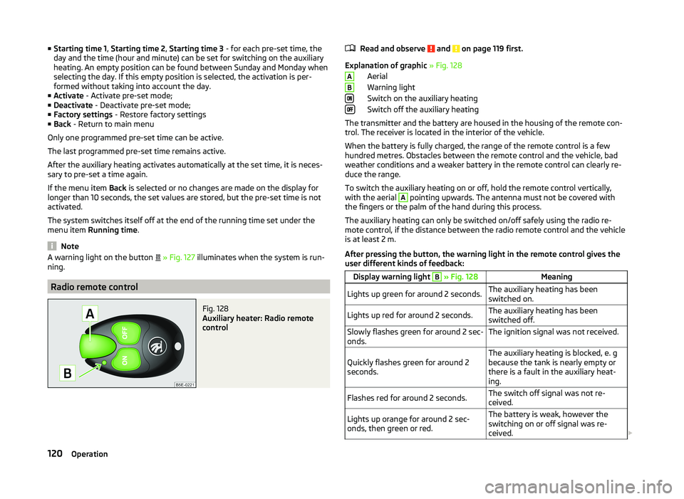
Fig. 128
Auxiliary heater: Radio remote
control
Read and observe and on page 119 first.
Explanation of graphic » Fig. 128
Aerial
Warning light
Switch on the auxiliary heating
Switch off the auxiliary heating
The transmitter and the battery are housed in the housing of the remote con- trol. The receiver is located in the interior of the vehicle.
When the battery is fully charged, the range of the remote control is a few
hundred metres. Obstacles between the remote control and the vehicle, bad
weather conditions and a weaker battery in the remote control can clearly re-
duce the range.
To switch the auxiliary heating on or off, hold the remote control vertically,
with the aerial
A
pointing upwards. The antenna must not be covered with
the fingers or the palm of the hand during this process.
The auxiliary heating can only be switched on/off safely using the radio re-
mote control, if the distance between the radio remote control and the vehicle
is at least 2 m.
After pressing the button, the warning light in the remote control gives the
user different kinds of feedback:
Display warning light B » Fig. 128MeaningLights up green for around 2 seconds.The auxiliary heating has been
switched on.Lights up red for around 2 seconds.The auxiliary heating has been
switched off.Slowly flashes green for around 2 sec-
onds.The ignition signal was not received.Quickly flashes green for around 2
seconds.The auxiliary heating is blocked, e. g
because the tank is nearly empty or
there is a fault in the auxiliary heat-
ing.Flashes red for around 2 seconds.The switch off signal was not re-
ceived.Lights up orange for around 2 sec-
onds, then green or red.The battery is weak, however the
switching on or off signal was re-
ceived. AB120Operation
Page 130 of 252

NoteThe following guidelines must be observed » page 121, Mobile phones and
two-way radio systems .
Connecting the phone to the hands-free system
To connect a mobile phone with the hands-free system, it is necessary to in-
terconnect the telephone and hands-free system. Detailed information on this
is provided in the operating instructions for your mobile phone. The following
steps must be carried out for the connection.
Connecting the telephone with the hands-free system via the rSAP profile
›
Activate Bluetooth ®
and the visibility of your mobile phone on your tele-
phone. For certain mobile phones it is necessary to switch on first the rSAP
function.
›
Switch on the ignition.
›
Select the Phone - New user menu in the MAXI DOT display and wait until
the hands-free system has completed the search.
›
Select the phone you wish to connect from the list of units found.
›
Confirm the PIN 1)
.
›
If your SIM card is blocked by a PIN code, enter the PIN code for the SIM card
in your phone. The telephone connects to the hands-free system (during the
first connection you can only enter the PIN code in the MAXI DOT display when the vehicle is stationary, as this is the only situation when you can
choose whether the PIN code should be stored).
›
To save a new user, follow the instructions in the MAXI DOT display.
›
Reconfirm the rSAP command on your mobile phone to download the tele-
phone book and the identification data from the SIM card into the hands-free
system.
Connecting the telephone with the hands-free system via the HPP profile
›
Activate Bluetooth ®
and the visibility of your mobile phone on your tele-
phone.
›
Switch on the ignition.
›
Select the Phone - New user menu in the MAXI DOT display and wait until
the hands-free system has completed the search.
›
Select the phone you wish to connect from the list of units found.
› Confirm the PIN 1)
.›Follow the instructions on the MAXI DOT display and the mobile phone to
store a new user or to download the telephone book and identification data
from the SIM card into the hands-free system.
The telephone primarily connects via the rSAP profile.
If the PIN code was stored, the telephone is automatically detected and con- nected with the hands-free system the next time the ignition is switched on.
Check your mobile phone to see whether this automatic connection has been
established.
Disconnecting the connection
› By removing the key from the ignition lock (the connection is disconnected
during a telephone call).
› By disconnecting the hands-free system in the mobile phone.
› Select the user by disconnecting the user in the MAXI DOT display in the
Bluetooth - User menu option - Disconnect.
On vehicles which are fitted with a radio or navigation system at the factory, it
is possible to terminate the telephone call after removing the key from the ig-
nition lock by pressing the button on the touchscreen of the radio 2)
or naviga-
tion system; refer to the » Operating instructions for the radio or navigation
system .
Note
■
In the memory of the hands-free system, up to three users can be stored,
whereby the hands-free system can only communicate actively with one user.
If a connection is established with a fourth mobile phone, one of the users
must be deleted.■
When connecting to the hands-free system, follow the instructions on your
mobile phone.
1)
Depending on the Bluetooth ®
version on the mobile phone, an automatically generated 6-digit PIN (SSP)
will either be displayed, or a 16-digit code displayed in the MAXI DOTdisplay will need to be entered into
your mobile phone and confirmed within 30 seconds by following the instructions on your mobile phone
display.
2)
Does not apply for Radio Swing.
127Communication and multimedia
Page 134 of 252
If the Pushbutton menu item is selected in the instrument cluster, the Wi-Fi
connection is made automatically.
If the WPS PIN menu item is selected in the instrument cluster, then a PIN
must be entered in the device to be connected and the instrument cluster.
Use WLAN network in MAXI DOT display
When a Wi-Fi network is switched on, the following menu items are displayed
when the Wi-Fi menu item is selected:
■ Off - Switch off the WLAN network (depending on the context)
■ Device list - Display a list of external devices
■ Active device - Display a list of active devices
■ Block - Block device connections
■ Known devices - Display a list of known devices
■ Rename - Rename the device
■ Block - Block device connections
■ Device blocked - Display of a list of blocked devices
■ Unblock - Remove the connection block
■ Delete lists - Delete device lists
■ Known devices - Delete the list of known devices
■ Device blocked - Delete the list of blocked devices
■ Both lists - Delete both device lists
■ Password - Use of password to log on to the WLAN network
■ Show - Display a password to log on to the WLAN network
■ Generate - Generate a new password to log on to the WLAN network
■ Wi-Fi Name - Use of WLAN network name
■ Show - Display the WLAN network name
■ Rename - Rename the WLAN network
■ WPS config. - Wi-Fi network connection using WPS
■ Pushbutton - Automatic connection
■ WPS PIN - PIN entry for the connection
■ Data counter - Display information about the volume of data transferred
■ Current Connection - display of the volume of data transferred for the cur-
rent connection
■ Total - Display of the total volume of data transferred
■ Reset - Resetting of the information about the volume of data transferred
■
Settings - WLAN network settings
■ Access point - Access point settings
■ Settings - Access point management
■ APN - Change the access point name
■ User name - User Name
■ Password - Password
■ Reset - Reset access point factory settings
■ Prioritisation - Set the connection priority
■ Calls - Set the connection priority for calls
■ Data - Set the connection priority for data transfer
■ Encryption - Set the encryption
■ WPA2 - Enable WPA 2 encryption
■ Open - No encryption
■ Visibility - Set the WLAN network visibility
■ Visible - WLAN network is visible to other devices
■ Invisible - WLAN network is not visible to other devices
■ Data roaming - Set the data roaming
■ No roaming - Data roaming is not allowed
■ Allow - Data roaming is allowed
■ Always ask - Question setting for data roaming
■ Wi-Fi Channel - Select WLAN network channels (preferably set to channel
11) ■ Channel 1 ... Channel 11 - Display the WLAN network channels
■ Reset - Reset Wi-Fi network factory settings
Voice control
Introduction
This chapter contains information on the following subjects:
Dialogue
132
Voice commands - GSM II
133
Voice commands - GSM III
133131Communication and multimedia
Page 135 of 252
DialogueFig. 130
Multifunction steering wheel
The voice control system (hereinafter referred to as the system) makes it pos-
sible to use voice commands for some functions of the hands-free system.
The period of time during which the system is ready to receive voice com-
mands and to carry them out is called a dialogue. The system gives audible
feedback and guides you if necessary through the relevant functions.
Optimum understanding of the voice commands depends on several factors. › Speak with a normal tone of voice without intonation and excessive pauses.
› Avoid a bad pronunciation.
› Close the doors, windows and sliding roof, to reduce or stop disturbing exte-
rior noise.
› It is recommended to speak louder at higher speeds, so that the tone of your
voice is louder than the increased surrounding noise.
› During the dialogue, limit additional noise in the vehicle, e.g. passengers talk-
ing at the same time.
› Do not speak, if the system makes an announcement.
The microphone for voice control is inserted in the moulded headliner and di- rected to the driver and front passenger. Therefore the driver and the front
passenger can operate the equipment.
Entering a phone number
The telephone number can be entered as a continuous series of individually
spoken digits (the whole number at once) or in the form of digital blocks (sepa-
rated by short pauses). After each order of digits (separation through brief
voice pause) all of the digits detected up to now are repeated by the system.
The digits 0 - 9, symbols +, , # are permitted. The system detects no continu-
ous digit combinations such as twenty-three, but only individually spoken dig-
its (two, three).
Activating voice control - GSM II
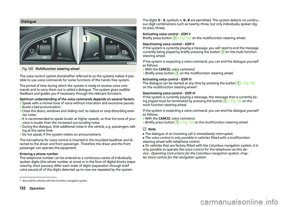
Briefly press button 1
» Fig. 130 on the multifunction steering wheel.
Deactivating voice control - GSM II
If the system is currently playing a message, you will need to end the message
currently being played by briefly pressing the button
1
on the multi function
steering wheel.
If the system is expecting a voice command, you can end the dialogue yourself
as follows.
› With the
CANCEL voice command.
› Briefly press button
1
on the multifunction steering wheel.
Activating voice control - GSM III
The dialogue can be started at any time by pressing the button
1
» Fig. 130
on the multifunction steering wheel 1)
.
Deactivating voice control - GSM III
If the system is currently playing a message, the message that is currently be-
ing played must be terminated by pressing the button
1
» Fig. 130 on the
multi function steering wheel.
If the system is expecting a voice command, you can end the dialogue yourself
as follows.
› With the
CANCEL voice command.
› Briefly press button
1
» Fig. 130 on the multifunction steering wheel.
Note
■
The dialogue of an incoming call is immediately interrupted.■The voice control is only possible in vehicles fitted with a multifunction
steering wheel with telephone control.■
On vehicles that are factory fitted with the Columbus navigation system, it is
only possible to operate the voice control for the telephone via this de-
vice » Operating instructions for the Columbus navigation system , chap-
ter Voice control for the navigation system .
1)
Not valid for vehicles with the Columbus navigation system.
132Operation
Page 141 of 252
Driving
Starting off and Driving
Starting and stopping the engine using the key
Introduction
This chapter contains information on the following subjects:
Electronic immobilizer
139
Ignition Switch
139
Starting the engine
139
Stopping the engine
140
Starting and stopping the engine on vehicles with the KESSY sys-
tem » page 140 .
The engine can only be started using a correctly coded original key.
The engine running noises may louder at first be louder for a short time after
starting the cold engine. This is quite normal and is not an operating problem.
WARNING■ When the vehicle is travelling with the engine off, the ignition key must
always be in position 2 » Fig. 134 on page 139 (ignition switched on). This
position is confirmed by the appearance of certain indicator lamps in the in-
strument cluster. ■If the key is not in position 2,
it could unexpectedly lock the steering -
danger of accident!
■
Only pull the ignition key from the ignition lock when the vehicle has
come to a complete stop (by applying the handbrake). Otherwise, the steer-
ing could be blocked – risk of accident!
■
Never leave the key in the vehicle when you exit the vehicle. Unauthor-
ized persons, such as children, for example, could lock the car, turn on the
ignition or start the engine - there is a danger of injury and accidents!
■
Never leave the vehicle unattended with the engine running - there is
risk of accident, damage or theft!
■
Never switch off the engine before the vehicle is stationary – risk of acci-
dent!
WARNING■ Never leave the engine running in unventilated or closed rooms. The en-
gine's exhaust gases also contain the odourless and colourless carbon
monoxide, a poisonous gas – risk of death. ■ Carbon monoxide can cause unconsciousness and death.■
Do not leave any items (e.g. cleaning cloths or tools) in the engine com-
partment. This presents a fire hazard and the risk of engine damage.
■
Never cover the engine with additional insulation material (e.g. with a
cover) – risk of fire!
CAUTION
■ The starter must only be operated when the engine is not running and the
vehicle is at a standstill. The starter or engine can be damaged if the starter is
activated when the engine is running 3
» Fig. 134 on page 139 .
■
Do not tow start the engine – there is a risk of damaging the engine and the
catalytic converter. The battery from another vehicle can be used as a jump-
start aid » page 211 , Jump-starting .
CAUTION
■
Avoid high engine revolutions, full throttle and high engine loads before the
engine has reached its operating temperature – risk of damaging the engine!■
Do not switch the engine off immediately at the end of your journey after the
engine has been operated over a prolonged period at high loads but leave it to
run at an idling speed for about 1 minute. This prevents any possible accumula-
tion of heat when the engine is switched off.
For the sake of the environment
Do not warm up the engine while the vehicle is stationary. If possible, start
your journey as soon as the engine has started. Through this the engine rea-
ches its operating temperature more rapidly and the pollutant emissions are
lower.
Note
After switching off the ignition, the radiator fan can intermittently continue to
operate for approx. 10 minutes.138Driving
Page 142 of 252
Electronic immobilizerRead and observe
and on page 138 first.
An electronic chip is integrated in the head of the key. The immobiliser is deac-
tivated with the aid of this chip when the key is inserted in the ignition lock.
The electronic immobiliser is automatically activated when the ignition key is
withdrawn from the lock.
The engine will not start if a non-authorized ignition key is used.
The following message is shown in the instrument cluster display. Immobilizer active.
IMMOBILIZER
Ignition Switch
Fig. 134
Positions of the vehicle key in
the ignition lock
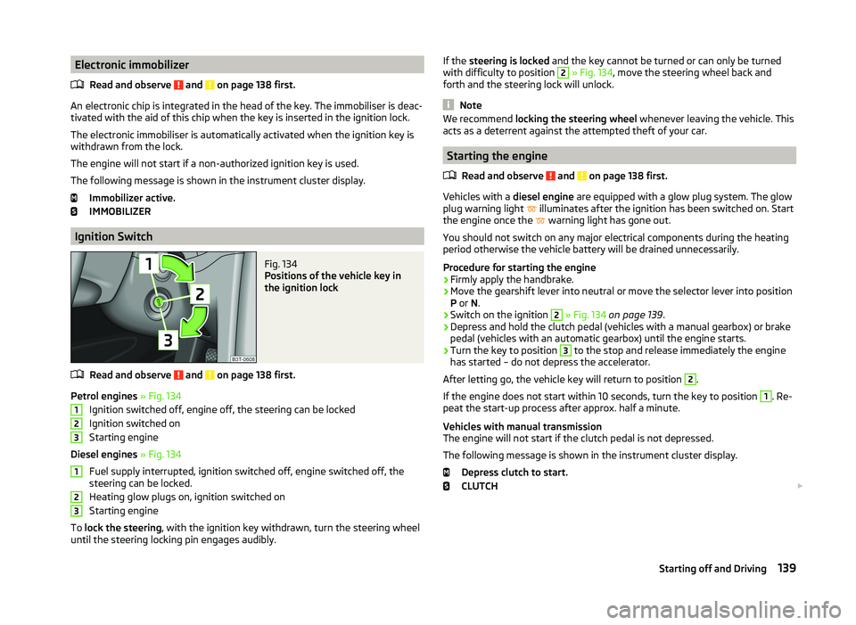
Read and observe and on page 138 first.
Petrol engines » Fig. 134
Ignition switched off, engine off, the steering can be locked
Ignition switched on
Starting engine
Diesel engines » Fig. 134
Fuel supply interrupted, ignition switched off, engine switched off, the
steering can be locked.
Heating glow plugs on, ignition switched on
Starting engine
To lock the steering , with the ignition key withdrawn, turn the steering wheel
until the steering locking pin engages audibly.
123123If the steering is locked and the key cannot be turned or can only be turned
with difficulty to position 2 » Fig. 134 , move the steering wheel back and
forth and the steering lock will unlock.
Note
We recommend locking the steering wheel whenever leaving the vehicle. This
acts as a deterrent against the attempted theft of your car.
Starting the engine
Read and observe
and on page 138 first.
Vehicles with a diesel engine are equipped with a glow plug system. The glow
plug warning light illuminates after the ignition has been switched on. Start
the engine once the warning light has gone out.
You should not switch on any major electrical components during the heating
period otherwise the vehicle battery will be drained unnecessarily.
Procedure for starting the engine
›
Firmly apply the handbrake.
›
Move the gearshift lever into neutral or move the selector lever into position
P or N.
›
Switch on the ignition
2
» Fig. 134 on page 139 .
›
Depress and hold the clutch pedal (vehicles with a manual gearbox) or brake
pedal (vehicles with an automatic gearbox) until the engine starts.
›
Turn the key to position
3
to the stop and release immediately the engine
has started – do not depress the accelerator.
After letting go, the vehicle key will return to position
2
.
If the engine does not start within 10 seconds, turn the key to position
1
. Re-
peat the start-up process after approx. half a minute.
Vehicles with manual transmission
The engine will not start if the clutch pedal is not depressed.
The following message is shown in the instrument cluster display. Depress clutch to start.
CLUTCH
139Starting off and Driving