brake sensor SKODA SUPERB 2009 Owner´s Manual
[x] Cancel search | Manufacturer: SKODA, Model Year: 2009, Model line: SUPERB, Model: SKODA SUPERB 2009Pages: 252, PDF Size: 16.33 MB
Page 36 of 252

Display of the second speedRead and observe
on page 30 first.
The display can show the current speed in mph 1)
.
This feature is provided for driving in countries with different units for speed.
MAXI DOT display
The display of the second speed can be set in the Alt. speed dis. menu
item » page 47 , Settings .
Segment display
›
Press the
3
» Fig. 21 on page 30 key repeatedly, until the odometer display
flashes » page 32 .
›
Press the
7
key while the display is flashing.
The second speed is displayed instead of the odometer.
Display of the second speed can be disabled in the same way.
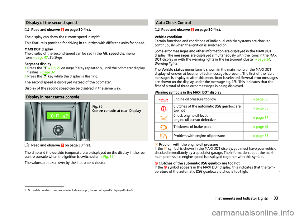
Display in rear centre console
Fig. 26
Centre console at rear: Display
Read and observe on page 30 first.
The time and the outside temperature are displayed on the display in the rear
centre console when the ignition is switched on » Fig. 26.
The values are taken over by the instrument cluster.
Auto Check Control
Read and observe
on page 30 first.
Vehicle condition
Certain functions and conditions of individual vehicle systems are checked
continuously when the ignition is switched on.
Some error messages and other information are displayed in the MAXI DOT
display. The messages are displayed simultaneously with the icons in the MAXI
DOT display or with the warning lights in the instrument cluster » page 34,
Warning lights .
The Vehicle status menu item is shown in the main menu of the MAXI DOT
display whenever at least one fault message is present. The first of the fault
messages is displayed after this menu item is selected. Several error messages
are shown on the display under the message e.g. 1/3. This indicates that the
first of a total of three error messages is being displayed.
Warning symbols in the MAXI DOT display
Engine oil pressure too low» page 36Clutches of the automatic DSG gearbox are
too hot» page 33Check engine oil level,
engine oil sensor defective» page 37Thickness of brake pads» page 41Problem with engine oil pressure» page 33
Problem with the engine oil pressure
If the symbol is shown in the MAXI DOT display, you must have your vehicle
checked immediately by a specialist garage. The information about the maxi-
mum permissible engine speed is displayed together with this symbol.
Clutches of the automatic DSG gearbox are too hot
If the symbol appears in the MAXI DOT display, this indicates that the tem-
perature of the automatic DSG gearbox clutches is too high.
1)
On models on which the speedometer indicates mph, the second speed is displayed in km/h.
33Instruments and Indicator Lights
Page 159 of 252

The ABS is activated faster and more effectively with the intervention of the
HBA.
Hill Hold Control (HHC)
Read and observe
and on page 154 first.
When driving on slopes, HHC allows you to move your foot from the brake ped-al to the accelerator pedal without having to use the handbrake.
The system holds the brake pressure produced by the activation of the brake pedal for approx. 2 seconds after the brake pedal is released.
The brake pressure drops gradually the more you operate the accelerator ped-
al. If the vehicle does not start off within 2 seconds, it starts to roll back.
HHC is active on slopes of >5 % when the driver door is closed. HHC is always only active on slopes when in forward or reverse start off. When driving down-
hill, it is inactive.
Parking aid
Introduction
This chapter contains information on the following subjects:
Function
157
Activation/deactivation
157WARNING■ The parking aid is not a substitute for the driver paying proper attention
and it is always the driver's responsibility to take care when reversing the
vehicle or carrying out similar manoeuvres. Pay particular attention to small
children and animals as they may not be recognised by the system sensors.■
Before reversing, you should make sure that there are no small obstacles,
such as rocks, thin posts, trailer drawbars etc. in front or behind your vehi-
cle. Such obstacles may not be recognised by the system sensors.
■
Under certain circumstances, surfaces of certain objects and types of
clothing cannot reflect the system signals. Thus, these objects or people
who wear such clothing are not recognised by the System sensors.
■
External sound sources can have a detrimental effect on the system. Un-
der adverse conditions, this may cause objects or people to not be recog-
nised by the system.
CAUTION■ If a warning signal sounds for about 3 seconds after activating the system
and there is no obstacle close to your car, this indicates a system fault. The
fault is also indicated by the symbol
flashing in the button » Fig. 148 on
page 157 . Seek help from a specialist garage.■
The sensors must be kept clean (free of ice, etc.) to enable the system to op-
erate properly.
■
Under adverse weather conditions (heavy rain, water vapour, very low or
high temperatures etc.), the system function may be limited - “incorrect recog-
nition of obstacle”.
■
Additionally installed accessories such as e.g. bicycle carriers can impair the
system function.
Note
■ The signal tones for front obstacle recognition are factory-set to be higher
than for rear obstacle recognition.■
If not all fields around the vehicle are shown after the system is activated,
the vehicle will need to be moved a few metres forwards or in reverse.
■
The sound of the park assist can be adjusted via the MAXI DOT display in the
Assistants menu option » page 47.
■
If the system is activated and the selector lever of the automatic gearbox is
in position P (the vehicle cannot move), the warning tone is interrupted and no
obstacles are displayed.
156Driving
Page 224 of 252

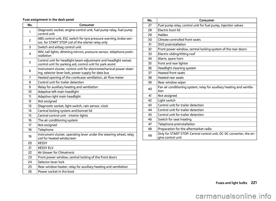
Fuse assignment in the dash panelNo.Consumer1Diagnostic socket, engine control unit, fuel pump relay, fuel pump
control unit2ABS control unit, ESC switch for tyre pressure warning, brake sen-
sor, for START STOP coil of the starter relay only3Switch and airbag control unit4WIV, tail lights, dimming mirrors, pressure sensor, telephone prein-
stallation5Control unit for headlight beam adjustment and headlight swivel,
control unit for parking aid, control unit for park assist6Instrument cluster, control unit for electromechanical power steer-
ing, selector lever lock, power supply for data bus7Heated opening of the crankcase ventilation, air flow meter8Control unit for trailer detection9Relay for auxiliary heating and ventilation10Adaptive left main headlight11Adaptive right main headlight12Not assigned13Diagnostic socket, light switch, rain sensor, clock14Central locking system and bonnet lid15Central control unit - interior lights16The air conditioning system17Not assigned18Telephone19Instrument cluster, operating lever under the steering wheel, relay
coil for heated windscreen20KESSY21KESSY ELV22Air blower for Climatronic23Front power window, central locking of the front doors24Selector lever lock25Rear window heater, relay for auxiliary heating and ventilation26Power socket in the bootNo.Consumer27Fuel pump relay, control unit for fuel pump, injection valves28Electric boot lid29Haldex30Climate controlled front seats31DVD preinstallation32Front power window, central locking system of the rear doors33Electric sliding/tilting roof34Alarm, spare horn35front and rear lighter36Headlight cleaning system37Heated front seats38Heated rear seats39Rear window wiper40Fan air conditioning system, relay for auxiliary heating and ventila-
tion41Not assigned42Light switch43Control unit for trailer detection44Control unit for trailer detection45Control unit for trailer detection46Switch for seat heating47Telephone preinstallation48Preparation for the aftermarket radio49Only for START STOP: Central control unit, DC-DC converter, the en-
gine control unit221Fuses and light bulbs
Page 226 of 252

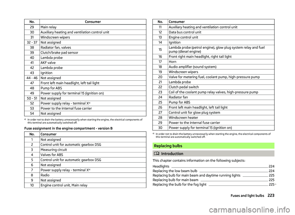
No.Consumer29Main relay30Auxiliary heating and ventilation control unit31Windscreen wipers32 - 37Not assigned38Radiator fan, valves39Clutch/brake pad sensor40Lambda probe41AKF valve42Lambda probe43Ignition44 - 46Not assigned47Front left main headlight, left tail light48Pump for ABS49Power supply for terminal 15 (ignition on)50 - 51Not assigned52Power supply relay - terminal Xa)53Power to the internal fuse carrier54Not assigneda)
In order not to drain the battery unnecessarily when starting the engine, the electrical components of
this terminal are automatically switched off.
Fuse assignment in the engine compartment - version B
No.Consumer1Not assigned2Control unit for automatic gearbox DSG3Measuring circuit4Valves for ABS5Control unit for automatic gearbox DSG6Not assigned7Power supply relay - terminal X a)8Radio9Not assigned10Engine control unit, Main relayNo.Consumer11Auxiliary heating and ventilation control unit12Data bus control unit13Engine control unit14Ignition15Lambda probe (petrol engine), glow plug system relay and fuel
pump (diesel engine)16Front right main headlight, right tail light17Horn18Audio amplifier (sound system)19Windscreen wipers20Valve for metering fuel, coolant pump, high-pressure pump21Lambda probe22Clutch pedal switch23Coil of the coolant pump relay valves, high-pressure pump24Radiator fan25Pump for ABS26Front left main headlight, left tail light27Control unit for glow plug system28Windscreen heater29Power to the internal fuse carrier30Power supply for terminal 15 (ignition on)a)
In order not to drain the battery unnecessarily when starting the engine, the electrical components of
this terminal are automatically switched off.
Replacing bulbs
Introduction
This chapter contains information on the following subjects:
Headlights
224
Replacing the low beam bulb
224
Replacing bulb for main beam and daytime running lights
225
Replacing bulb for main beam
225
Replacing the bulb for the fog light
225
223Fuses and light bulbs