Light SKODA SUPERB 2010 2.G / (B6/3T) Owner's Manual
[x] Cancel search | Manufacturer: SKODA, Model Year: 2010, Model line: SUPERB, Model: SKODA SUPERB 2010 2.G / (B6/3T)Pages: 287, PDF Size: 16.59 MB
Page 232 of 287
Wheels and Tyres231
Using the system
Safety
Driving Tips
General Maintenance
Breakdown assistance
Technical Data
The date of manufacture
is also stated on the tyre wall (possibly only on the inside of
wheel).
DOT ... 20 09...
means, for example, that the tyre was ma nufactured in the 20th week of the year 2009.
Any spare wheel which differs from the tyres fitted to the vehicle (e.g. winter tyres or
low-profile tyres) should only be used for a short time in the event of a puncture and
when adopting an appropriately cautious styl e of driving. It should be replaced as
quickly as possible by a normal wheel.
WARNING
Only use those tyres or wheel rims which have been approved for your
model of Škoda Auto vehicle. Failure to observe this instruction will adversely
affect the road safety of your vehicle - risk of accident! Approval and licencing
of your vehicle on public roads may also become void as a result.
You must on no account drive at a high er speed than is permissible for your
tyres - risk of an accident resulting from tyre damage and loss of control over
your vehicle.
Tyres which are 6 years old or more should only be fitted in exceptional
cases and when adopting an approp riately cautious style of driving.
Never fit tyres which have already been used without having adequate
knowledge of their previous history. Tyre s age even if they have not been used
at all or only very little. A spare tyre must only be used in exceptional cases and
only then when adopting an appropriately cautious style of driving.
Do not, where possible, replace individu al tyres but at least replace them on
both wheels of a given axle at the same time. Always fit the tyres with the
deeper tread depth to the front wheels.For the sake of the environment
Old tyres must be disposed of in conf ormity with the appropriate regulations.
Note
It is not normally possible to fit wheels from other models of cars for technical reasons.
This may also apply in certain circumstances to the wheels of the same type of
vehicle.Wheel boltsWheels and wheel bolts are matched to each other in terms of design. Each time you
fit other wheels - e.g. light alloy wheels or wheels with winter tyres - you must therefore
also use the matching wheel bolts of the corr ect length and shape of spherical cap. This
is essential to ensure that the wheels are tightly fitted and that the brake system oper-
ates properly.
If you retrofit wheel trims (or have this done), please also ensure that an adequate
flow of air remains assured for cooling the brake system.
The authorised Škoda Service Partners are instructed in the technical possibilities
which exist regarding converting or retrofitting tyres, wheels and wheel trims.
WARNING
In case of incorrect treatment of the wheel bolts, the wheel can loosen when
the car is moving - risk of accident!
The wheel bolts must be clean and must turn easily. However, they must
never be treated with grease or oil.
If the wheel bolts are tightened to a too low tightening torque, the rim can
lossen when the car is moving - risk of accident! A tightening torque which is
too high can damage the bolts and threads and this can result in permanent
deformation of the contac t surfaces on the rims.Caution
The prescribed tightening torque of the wh eel bolts for steel and light alloy wheels is
120 Nm.
s3fg.2.book Page 231 Friday, April 30, 2010 12:17 PM
Page 238 of 287

Breakdown assistance237
Using the system
Safety
Driving Tips
General Maintenance
Breakdown assistance
Technical Data
The spare wheel lies in a well under the floor covering of the luggage compartment and
is fixed in place using special screws
page 236, fig. 195 .
Before removing the spare wheel, you must take out the box with the vehicle tool kit
box page 236, fig. 194.
One should check the inflation pressure in the spare wheel (at best when generally
checking the tyre air pressures - see sign on the fuel filler flap page 228) to ensure
that the spare wheel is always ready to use.
Temporary spare wheel
A warning label displayed on the rim of the temporary spare wheel indicates that your
vehicle is equippe d with a temporary spare wheel.
Please observe the following notes when driving with a temporary spare wheel:
The warning label must not be covered after installing the wheel.
Do not drive faster than 80 km/h with this spare wheel and pay particular attention
while driving. Avoid accelerating at full throttle, sharp braking and fast cornering.
The inflation pressure for this spare wheel is identical to the inflation pressure of
the standard tyres. The temporary spare wheel R 18 must have an inflation pressure of
420 kPa (4.2 bar)!
Use this spare wheel only to reach the nearest specialist garage as it is not intended
for continuous use.
No other summer or winter tyres must be mounted on the rim of the spare wheel
R 18.
Changing a wheelPreliminary workThe following steps should be carried ou t before actually changing the wheel.
– If it is necessary to change a wheel, park the vehicle as far away as possible from
the traffic flow. The place you choose should be level.
–Have all the occupants get out. While changing a wheel, the occupants of the
vehicle should not stand on the road (e.g. behind a crash barrier).
– Apply the handbrake firmly. –Engage
1st gear or if your vehicle is fitted with an automatic gearbox, position the
selector lever into position P .
– If a trailer is coupled, uncouple it.
–Take the vehicle tool kit page 236 and the spare wheel* page 236 out of the
luggage compartment.
WARNING
If you find yourself in flowing traffic switch on the hazard warning lights
system and place the warning triangle on the side of the road at the prescribed
distance from your vehicle while observin g all national legal provisions. In this
way you are protecting not only yourself but also other road users.
Never start the engine with the vehicle si tting on the raised jack - danger of
suffering injury.Caution
If you have to change a wheel on a slope fi rst block the opposite wheel with a stone or
similar object in order to secure the vehicle from unexpectedly rolling away.
Note
Comply with the national legal regulations.Changing a wheelAlways change a wheel on a level surface as far as possible.
– Take off the full wheel trim* page 238 or the wheel trim cap page 239 or the
caps page 239.
– In the case of light alloy wheels remove the wheel trim cap page 239.
– First of all slacken the safety wheel bolt * and afterwards the other wheel bolts page 239.
– Jack up the vehicle until the wheel to be changed is clear of the ground
page 240.
– Unscrew the wheel bolts and place them on a clean surface (cloth, paper etc.).
s3fg.2.book Page 237 Friday, April 30, 2010 12:17 PM
Page 239 of 287
Breakdown assistance
238
– Take off the wheel.
– Fit on the spare wheel and ti ghten the wheel bolts slightly.
–Lower the car.
– Tighten the wheel bolts firmly, alternately and diagonally using the wheel wrench (crosswise) and last the safety wheel bolt* page 239.
– Mount the full wheel trim/wheel trim cap or the caps.
Note
All bolts must be clean and must turn easily.
You must never grease or oil the wheel bolts!
When fitting on unidirectional tyres, ensu re that the tyres rotate in the correct
direction page 228.
Subsequent stepsAfter changing the wheel, you must perform the following steps.
– Stow and attach the replaced wheel in the spare wheel well using a special screw
page 236, fig. 195 .
– Stow the vehicle tool kit in the space provided.
– Check the tyre pressure on the spare wheel just mounted as soon as possible.
– Have the tightening torque of the wheel bolts checked with a torque wrench as
soon as possible. Steel and light alloy wh eels must be tightened to a tightening
torque of 120 Nm .
– Change the damaged wheel or consult a specialist garage about possibilities for getting repairs done.
WARNING
It is necessary to observe the guidelines given on page 230 if the vehicle is
subsequently fitted with tyres which are different to those it was fitted with at
the works.
Note
If you find, when changing the wheel, that the wheel bolts are corroded and diffi-
cult to turn, the bolts must be replaced before checking the tightening torque.
Drive cautiously and only at a moderate speed to a workshop where the tightening
torque can be checked.
Full wheel trim*Pulling off– Hook the clamp found in the vehicle tool ki t into the reinforced edge of the full
wheel trim.
– Push the wheel key through the clamp, support the wheel key at the tyre and pull off the wheel trim.Installing– First press the full wheel trim onto the wheel at the valve opening provided. Then
press the full wheel trim into the wheel in such a way that its entire circumference
locks correctly in place.
Caution
Use the pressure of your hand, do not knock on the full wheel trim! Heavy knocks
mainly on the points where the full wheel trim has not been inserted into the wheel,
can result in damage to the guide and centering elements of the full wheel trim.
Check for yourself that the safety wheel bolt is located in the hole in the area of the
valve before fitting the full wheel trim onto a steel wheel which is attached with a safety
wheel bolt page 240, “Securing wheels against being stolen*”.
s3fg.2.book Page 238 Friday, April 30, 2010 12:17 PM
Page 240 of 287

Breakdown assistance239
Using the system
Safety
Driving Tips
General Maintenance
Breakdown assistance
Technical Data
Wheel bolts with caps*Pulling off– Push the plastic clip sufficiently far onto the cap until the inner catches of the clip
are positioned at the collar of the cap and detach the cap fig. 196 .Installing– Push the caps fully onto the wheel bolts.
The caps are located in the well of the luggage compartment.Wheel trim caps*Pulling off– Carefully remove the wheel tr im cap using the wire clamp fig. 197 .
Slackening and tightening wheel bolts
Slacken the wheel bolts before jacking up the vehicle.Slackening wheel bolts– Push the wheel wrench* fully onto the wheel bolt
16).
– Grasp the end of the wrench* and turn the bolt about one turn to the left
fig. 198 .
Tightening wheel bolts– Push the wheel wrench* fully onto the wheel bolt
16).
– Grasp the end of the wrench* and turn the bolt to the right until it is tight.
WARNING
Slacken the wheel bolts only a little (about one turn) as long as the vehicle has
not yet been jacked up - risk of an accident!.
Note
Apply pressure carefully with your foot to the end of the wrench* if it proves difficult
to slacken the bolts. Hold tight on the vehicl e when doing this and ensure that you have
a steady position.
Fig. 196 Removing the cap.Fig. 197 Pulling off wheel trim cap on
light alloy wheels
16)Use the appropriate adapter for slackening and tightening the safety wheel bolts page 240.
Fig. 198 Changing a wheel: Slackening
wheel bolts
s3fg.2.book Page 239 Friday, April 30, 2010 12:17 PM
Page 241 of 287
Breakdown assistance
240
Raise vehicle
You have to raise the vehicle with the lifting jack* in order to be able to
take off the wheel.Position the lifting jack* by selecting the ja cking point which is closest to the wheel to
be removed fig. 199 . The jacking point is located directly below the engraving in the
lower sill.
– Position the lifting jack* below the jacking point and move it up until its claw is positioned directly below the vertical web of the lower sill.
– Align the lifting jack* so that its claw grasps the web of the lower sill and the
base plate is resting flat on the floor.
– Turn the lifting jack* up further until the wheel is just clear of the ground.
Ground below the lifting jack which is soft and slippery can cause the vehicle to slip
off the jack. It is therefore always necessary to place the lifting jack* on a solid surface
or use a wide and stable base. Use a non-sl ip base (e.g. a rubber foot mat) if the
surface is smooth , such as cobbled stones, a tiled floor, etc.
WARNING
Always raise the vehicle with the doors closed - risk of injury!
Take suitable measures to prevent the base of the lifting jack from slipping
off - risk of injury!
Not positioning the lifting jack at the specified points can result in damage
to the vehicle. The jack can al so slip off if it does not have sufficient grip - risk of
injury!
It is important to support the vehicle with suitable supporting blocks if you
wish to work under the lifted vehicle - risk of injury!
Securing wheels against being stolen*
You need a special adapter for sl ackening the safety wheel bolts.– Pull off the full wheel trim/cap from the wheel hub or cap from the safety wheel
bolt.
– Insert the adapter fig. 200 with its toothed side full y into the inner toothing
of the safety wheel bolt in such a way that only the outer hexagon is jutting out
fig. 200 .
– Insert the wheel wrench fully onto the adapter .
– Slacken the wheel bolt, or tighten it firmly page 239.
– Reinstall the full wheel trim/wheel cap after removing the adapter or place the cap onto the safety wheel bolt.
– Have the tightening torque checked with a torque wrench as soon as possible.
Steel and light alloy wheels must be tightened to a tightening torque of 120 Nm.
Fig. 199 Changing a wheel: Jacking
points for positioning lifting jack
AA
AB
WARNING (continued)
Fig. 200 Safety wheel bolt with adapter
AB
AA
AB
s3fg.2.book Page 240 Friday, April 30, 2010 12:17 PM
Page 244 of 287

Breakdown assistance243
Using the system
Safety
Driving Tips
General Maintenance
Breakdown assistance
Technical Data
– Release the clutch particularly gently wh
en starting off or depress the accelerator
particularly gently if your vehicle is fitted with an automatic gearbox.
Driver of the towed vehicle– Switch the ignition on so that the steeri ng wheel is not blocked and you can also
operate the turn signal lights, the headlight flasher, the windscreen wipers and
windscreen washer system.
– Take the vehicle out of gear or move the selector lever into position N if your
vehicle is fitted with an automatic gearbox.
– Note that the brake servo unit and power steering only operate if the engine is running. You will require significantly grea ter physical force to depress the brake
pedal and to steer th e vehicle if the engine is not running.
– Ensure that the tow rope is always kept taught.
Tow rope or tow bar
A tow bar is safest way of towing a vehicle an d also minimizes any shocks. You can use
a tow rope only if a suitable tow bar is not available.
The tow rope must be elastic to protect the vehicle. Thus one should only use plastic
fibre rope or a rope made out of a similarly elastic material.
Only attach the tow rope to the towing eyes provided for this purpose page 243
and page 244.
Driving style
Towing another vehicle requires a certain am ount of practice. Both drivers should be
familiar with the particular points about to wing a vehicle. Unskilled drivers should not
attempt to tow in another vehicle or to be towed in.
One should be constantly vigi lant not to allow impermissibly high towing forces or
jerky loadings. There is always a risk of excessive stresses and damage resulting at the
points to which you attach the tow rope or tow bar when you attempt to tow a vehicle
which is not standing on a paved road.
Caution
If the gearbox of your vehicle no longer contains any oil because of a defect, your
vehicle must only be towed in with the driven wheels raised clear of the ground, or on
a special vehicle transporter or trailer.
Note
Please comply with any national legal provisions particularly regarding the
switched on signal systems, when towi ng in or tow-starting another vehicle.
The tow rope must not be twisted as it may in certain circumstances result in the
front towing eye being unscrewed out of your vehicle.
Front towing eye
The towing eye is stored in th e box for the vehicle tool kit.Fig. 203 Front bumper: Removing the cover / installing the towing eye– Take the cover out of the front bumper fig. 203 - left.
– Screw in the towing eye by hand to the left up to the stop fig. 203 - right and
tighten it as much as po ssible. For tightening, we recommend that you use for
example the wheel wrench*, the lashing eye of another vehicle or a similar object
which you can push through the eye.
– Put the cover in place after screwing out the towing eye again and press into place.
The cover must engage firmly.
s3fg.2.book Page 243 Friday, April 30, 2010 12:17 PM
Page 247 of 287
Fuses and light bulbs
246
Fuses and light bulbsElectric fusesReplacing fuses in the dash panel
Defect fuses must be replaced.Individual electrical circuits are protected by fuses. The fuses are located on the left
side of the dash panel behind the safety cover and under the cover in the engine
compartment on the left.
– Switch the ignition off and also the electrical component affected.
– Use a screwdriver to take off the fuse cover on the side of the dash panel fig. 205
or the fuse cover in the engine compartment page 247, fig. 206 .
– Find out which fuse belongs to the relevant component page 249, “Fuse assign-
ment in the dash panel”, page 247, “Fuse assignment in engine compartment -
version 1” or page 248, “Fuse assignment in engine compartment - version 2”.
– Take the plastic clip out of it s fixture in the fuse cover, insert it onto the respective
fuse and pull out this fuse.
– Defect fuses can be detected by their melted metal strips. Replace the defect fuse by a new fuse of the same ampere number.
– Fit on the fuse cover again. We recommend that you always have the
small box of replacement fuses in your
vehicle. You can obtain replacement fuses from the range of Škoda original parts or
from a specialist garage
17).
Colour coding of fuses
Caution
Never attempt to “repair” fuses and also do not replace them with a fuse of a higher
amperage - risk of fire! This may also caus e damage at another part of the electrical
system.
Have the electrical system checked as quickly as possible by a specialist garage if a
newly inserted fuse blows again after a short time.
Fig. 205 Fuse cover: left side of the dash
panel
17)The small box with replacement fuses is part of the basic equipping of the vehicle in some coun-
tries.
Colour
Maximum amperage
light brown
5
brown
7,5
red
10
blue
15
yellow
20
white
25
green
30
orange
40
red
50
s3fg.2.book Page 246 Friday, April 30, 2010 12:17 PM
Page 248 of 287
Fuses and light bulbs247
Using the system
Safety
Driving Tips
General Maintenance
Breakdown assistance
Technical Data
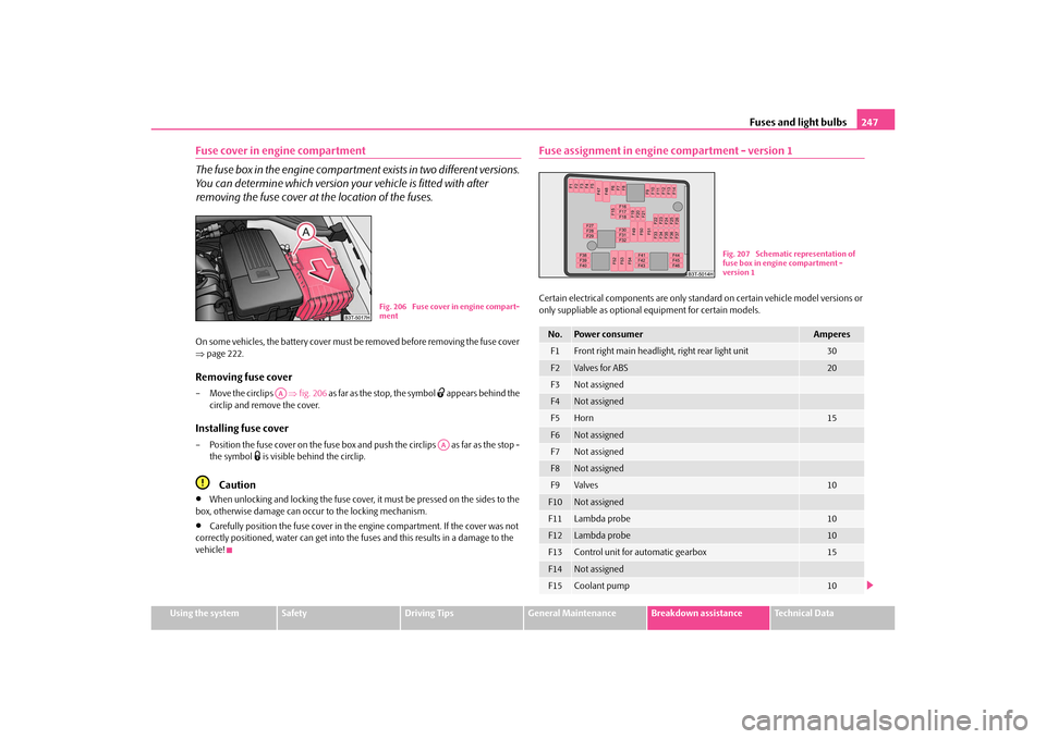
Fuse cover in engine compartment
The fuse box in the engine compartment exists in two different versions.
You can determine which version your vehicle is fitted with after
removing the fuse cover at the location of the fuses.On some vehicles, the battery cover must be removed before removing the fuse cover
page 222.Removing fuse cover– Move the circlips fig. 206 as far as the stop, the symbol
appears behind the
circlip and remove the cover.
Installing fuse cover– Position the fuse cover on the fuse box and push the circlips as far as the stop -
the symbol
is visible behind the circlip.
Caution
When unlocking and locking the fuse cover, it must be pressed on the sides to the
box, otherwise damage can occur to the locking mechanism.
Carefully position the fuse cover in the engine compartment. If the cover was not
correctly positioned, water can get into the fuses and this results in a damage to the
vehicle!
Fuse assignment in engine compartment - version 1Certain electrical components are only stan dard on certain vehicle model versions or
only suppliable as optional equipment for certain models.
Fig. 206 Fuse cover in engine compart-
ment
AA
AA
No.
Power consumer
Amperes
F1
Front right main headlight, right rear light unit
30
F2
Valves for ABS
20
F3
Not assigned
F4
Not assigned
F5
Horn
15
F6
Not assigned
F7
Not assigned
F8
Not assigned
F9
Valves
10
F10
Not assigned
F11
Lambda probe
10
F12
Lambda probe
10
F13
Control unit for automatic gearbox
15
F14
Not assigned
F15
Coolant pump
10
Fig. 207 Schematic representation of
fuse box in engine compartment -
version 1
s3fg.2.book Page 247 Friday, April 30, 2010 12:17 PM
Page 249 of 287
Fuses and light bulbs
248
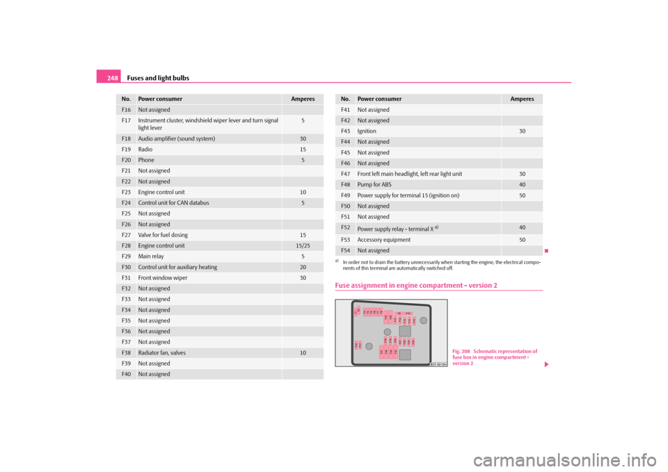
Fuse assignment in engine compartment - version 2
F16
Not assigned
F17
Instrument cluster, windshield wiper lever and turn signal
light lever
5
F18
Audio amplifier (sound system)
30
F19
Radio
15
F20
Phone
5
F21
Not assigned
F22
Not assigned
F23
Engine control unit
10
F24
Control unit for CAN databus
5
F25
Not assigned
F26
Not assigned
F27
Va lve for f uel d osi ng
15
F28
Engine control unit
15/25
F29
Main relay
5
F30
Control unit for auxiliary heating
20
F31
Front window wiper
30
F32
Not assigned
F33
Not assigned
F34
Not assigned
F35
Not assigned
F36
Not assigned
F37
Not assigned
F38
Radiator fan, valves
10
F39
Not assigned
F40
Not assigned
No.
Power consumer
Amperes
F41
Not assigned
F42
Not assigned
F43
Ignition
30
F44
Not assigned
F45
Not assigned
F46
Not assigned
F47
Front left main headlight, left rear light unit
30
F48
Pump for ABS
40
F49
Power supply for terminal 15 (ignition on)
50
F50
Not assigned
F51
Not assigned
F52
Power supply relay - terminal X
a)
40
F53
Accessory equipment
50
F54
Not assigned
a)In order not to drain the battery unnecessarily when starting the engine, the electrical compo-
nents of this terminal are automatically switched off.No.
Power consumer
Amperes
Fig. 208 Schematic representation of
fuse box in engine compartment -
version 2
s3fg.2.book Page 248 Friday, April 30, 2010 12:17 PM
Page 250 of 287
Fuses and light bulbs249
Using the system
Safety
Driving Tips
General Maintenance
Breakdown assistance
Technical Data
Certain electrical components are only standard on certain vehicle model versions or
only suppliable as optional
equipment for certain models.
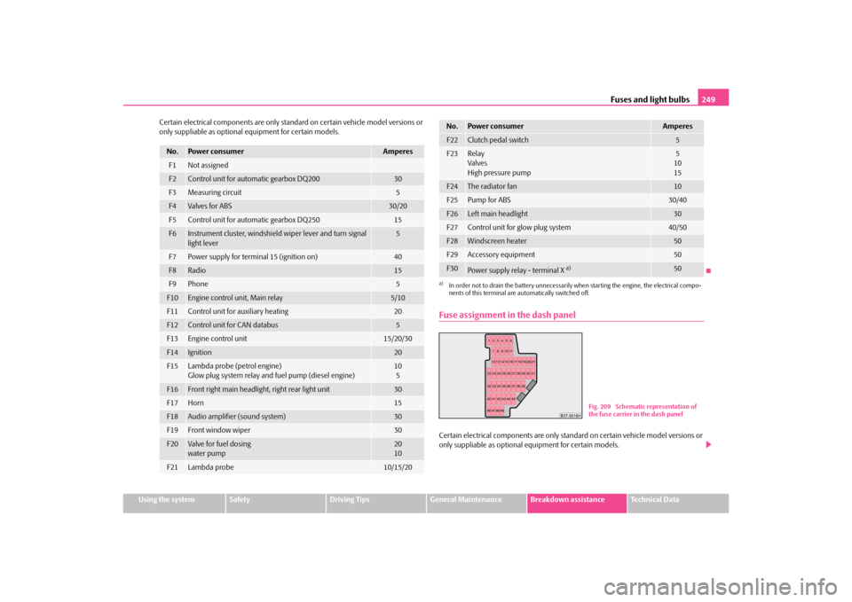
Fuse assignment in the dash panelCertain electrical components are only stan dard on certain vehicle model versions or
only suppliable as optional equipment for certain models.
No.
Power consumer
Amperes
F1
Not assigned
F2
Control unit for automatic gearbox DQ200
30
F3
Measuring circuit
5
F4
Va lve s for AB S
30/20
F5
Control unit for automatic gearbox DQ250
15
F6
Instrument cluster, windshield wiper lever and turn signal
light lever
5
F7
Power supply for terminal 15 (ignition on)
40
F8
Radio
15
F9
Phone
5
F10
Engine control unit, Main relay
5/10
F11
Control unit for auxiliary heating
20
F12
Control unit for CAN databus
5
F13
Engine control unit
15/20/30
F14
Ignition
20
F15
Lambda probe (petrol engine)
Glow plug system relay and fuel pump (diesel engine)
10
5
F16
Front right main headlight, right rear light unit
30
F17
Horn
15
F18
Audio amplifier (sound system)
30
F19
Front window wiper
30
F20
Va lve for f uel d osi ng
water pump
20
10
F21
Lambda probe
10/15/20
F22
Clutch pedal switch
5
F23
Relay
Valves
High pressure pump
5
10
15
F24
The radiator fan
10
F25
Pump for ABS
30/40
F26
Left main headlight
30
F27
Control unit for glow plug system
40/50
F28
Windscreen heater
50
F29
Accessory equipment
50
F30
Power supply relay - terminal X
a)
50
a)In order not to drain the battery unnecessarily wh en starting the engine, the electrical compo-
nents of this terminal are automatically switched off.No.
Power consumer
Amperes
Fig. 209 Schematic representation of
the fuse carrier in the dash panel
s3fg.2.book Page 249 Friday, April 30, 2010 12:17 PM