Engine SKODA SUPERB 2010 2.G / (B6/3T) Owner's Guide
[x] Cancel search | Manufacturer: SKODA, Model Year: 2010, Model line: SUPERB, Model: SKODA SUPERB 2010 2.G / (B6/3T)Pages: 287, PDF Size: 16.59 MB
Page 65 of 287
Lights and Visibility
64
Mode motorway
In the mode “motorway” the dispersion of the co ne of light is so widespread, that it illu-
minates also the left (and right)
7) lane of the motorway, so that the driver can react in
time to an obstacle or any other danger. The mode is activated stepwise as of a speed
of 90 km/h. It gains its greatest effectiveness at speeds above 120 km/h.
Tourist light
This mode makes it possible to drive in countries with opposing traffic system, driving
on the left/right, without dazzling the oncoming vehicles. When the mode “tourist
light” is active, the above mentioned modes and the side to side swivel of the headlight
is deactivated.
The mode “tourist light” is activated / deac tivated via the information display* in the
menu:
SETUP
Tr a v e l m o d e
Off
On
Cornering lights
The cornering lights are used to illuminate the curves by means of the cone of light
swiveling together with the front headlight with Xenon lights*. This function is active
when the speed of the car increases to more than 10km/h.
The swiveling function of the headlights ca n be switched off / on via the menu point
Assistants in the main menu of the information display* page 23.WARNING
If the cornering ligh ts are defective, the headlights are automatically lowered to
the emergency position, whic h prevents a possible dazzling of oncoming traffic.
Thus the illuminated length of the road is shortened. Drive carefully and have
the car inspected immediatel y by a specialist garage.
Note
The AHL system* complements the functions of the fog lights with the function
“CORNER” page 64 and the function of the dy namic headlamp beam adjustment*.
The System AHL* is solely delivered with Bi-Xenon gas discharge bulbs for low
beam and main beam lights.
Fog lights
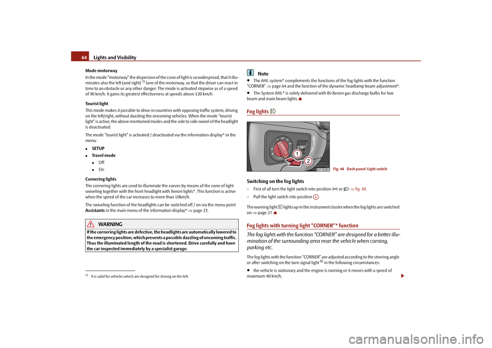
Switching on the fog lights– First of all turn the light switch into position
or fig. 48 .
– Pull the light switch into position .
The warning light
lights up in the instrument cluste r when the fog lights are switched
on page 27.
Fog lights with turning light “CORNER”* function
The fog lights with the function “CORNER” are designed for a better illu-
mination of the surrounding area near the vehicle when corning,
parking etc.The fog lights with the function “CORNER” ar e adjusted according to the steering angle
or after switching on the turn signal light
8) in the following circumstances:
the vehicle is stationary and the engine is running or it moves with a speed of
maximum 40 km/h,
7)It is valid for vehicles which are designed for driving on the left.
Fig. 48 Dash panel: Light switch
A1
s3fg.2.book Page 64 Friday, April 30, 2010 12:17 PM
Page 71 of 287
Lights and Visibility
70
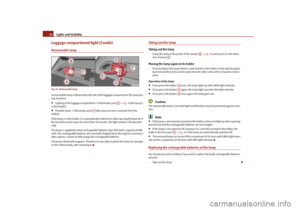
Luggage compartment light (Combi)Removeable lampFig. 58 Removeable lampA removeable lamp is fitted on the left side of the luggage compartment. This lamp has
two functions:
Lighting of the luggage compartment - it illuminates part fig. 58 (the lamp is
in the holder),
Portable lamp - it illuminates part (the lamp has been removed from the
holder).
If the lamp is in the holder, it is automatically switched on after opening the boot lid. If
the boot lid remains open for more than 10 minutes, the light switches off automati-
cally.
The lamp is supplied by three rechargeable batteries type AAA with a capacity of 600
mAh. The rechargeable batteries are constantly charged when the engine is running. It
takes approx. 3 hours to fully charge the rechargeable batteries.
The lamp is fitted with magnets. Therefore it is possible to attach the lamp, for example
on the vehicle body, after removing it.
Taking out the lampTaking out the lamp– Grasp the lamp at the points of the arrows fig. 58 and swivel it in the direc-
tion of arrow .Placing the lamp again in its holder– First of all place the lamp, which is switched off, in the holder on the side facing the
boot lid and then press on the lamp from th e other side until it is heard to lock in
place.
Operation of the lamp
If you press the button once, the lamp lights up with 100% light intensity.
If you press the button again, the lamp lights up with 50% light intensity.
If you press the button once again, the lamp goes out.Caution
The removeable lamp is not watertight and therefore must be protected against mois-
ture.
Note
If the lamp is not correctly inserted in the holder, it does not light up when opening
the boot lid and the rechargeable batteries are not charged.
If the lamp is not switched off, however it is correctly inserted in the holder, the
bulbs in the front part fig. 58 of the lamp are automatically switched off.
The removed lamp can remain lit for a maximum of 24 hours with 100% light inten-
sity and for a maximum of 48 hours with 50% light intensity.
Replacing the rechargeable batteries of the lampYou should proceed as follows if you wish to replace the faulty rechargeable batteries
yourself.
– Take out the lamp.
AB
AC
AD
AE
AAAAAA
AC
s3fg.2.book Page 70 Friday, April 30, 2010 12:17 PM
Page 72 of 287
Lights and Visibility71
Using the system
Safety
Driving Tips
General Maintenance
Breakdown assistance
Technical Data
– Lever off the cover of the rechargeable ba
tteries with a narrow and pointed object
at the point of the lock-off clips page 70, fig. 58 .
– Remove the faulty rechargeable batteries from the lamp.
– Insert the new rechargeable batteries.
– Insert the cover of the rechargeable batteries and press on it until it is heard to lock
in place.
WARNING
Pay particular attention when using the narrow and pointed object to change
the rechargeable batteries - risk of injury.
Caution
We recommend having the faulty rechargeab le batteries replaced by a specialist
garage. If the lamp is not corr ectly opened, it can be damaged.
For the sake of the environment
Dispose of the faulty rechargeable batteries in accordance with environmental regula-
tions.
Note
Pay attention to the correct polarity wh en replacing the rechargeable batteries.
The replacement rechargeable batteries must have the same specification as the
original rechargeable batteries. If other ty pes of rechargeable batteries are used, the
power output can be reduced and it can lead to a malfunction of the lamp.
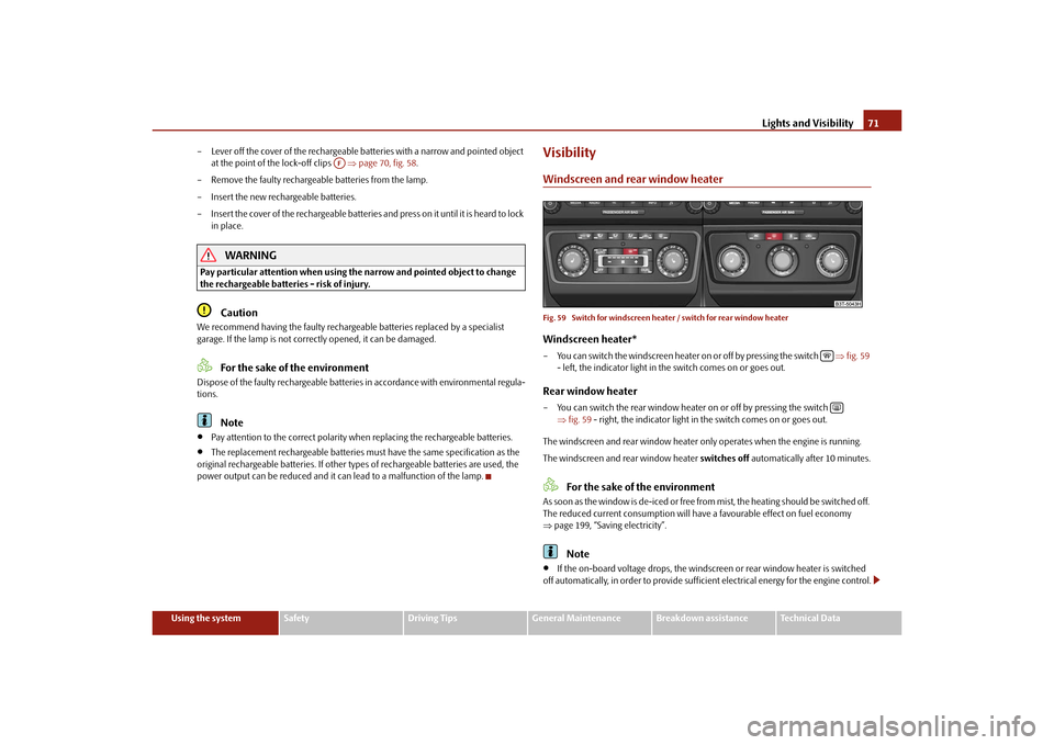
VisibilityWindscreen and rear window heaterFig. 59 Switch for windscreen heat er / switch for rear window heaterWindscreen heater*– You can switch the windscreen heater on or off by pressing the switch fig. 59
- left, the indicator light in th e switch comes on or goes out.Rear window heater– You can switch the rear window heater on or off by pressing the switch
fig. 59 - right, the indicator light in the switch comes on or goes out.
The windscreen and rear wind ow heater only operates when the engine is running.
The windscreen and rear window heater switches off automatically after 10 minutes.
For the sake of the environment
As soon as the window is de-iced or free from mist, the heating should be switched off.
The reduced current consumption will have a favourable effect on fuel economy
page 199, “Saving electricity”.
Note
If the on-board voltage drops, the windscre en or rear window heater is switched
off automatically, in order to provide sufficient electrical energy for the engine control.
AF
s3fg.2.book Page 71 Friday, April 30, 2010 12:17 PM
Page 78 of 287
Lights and Visibility77
Using the system
Safety
Driving Tips
General Maintenance
Breakdown assistance
Technical Data
Attaching a wiper blade– Position the wiper blade onto the wiper arm and lock the locking button .
– Check whether the wiper bl ade is correctly attached.
– Fold the windscreen wiper arm back onto the windscreen.
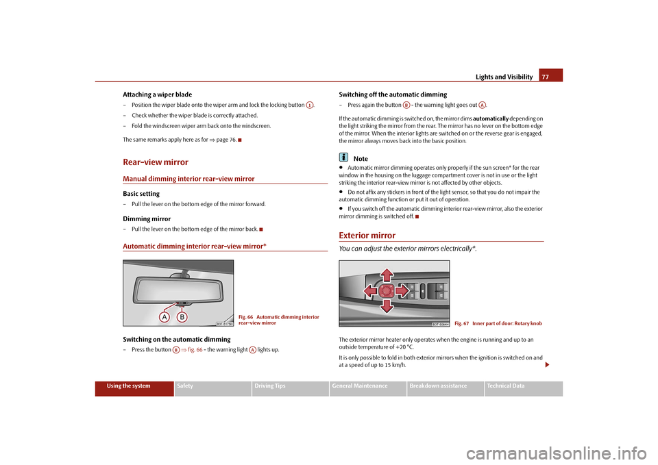
The same remarks apply here as for page 76.Rear-view mirrorManual dimming interior rear-view mirrorBasic setting– Pull the lever on the bottom edge of the mirror forward.Dimming mirror– Pull the lever on the bottom edge of the mirror back.Automatic dimming interior rear-view mirror*Switching on the automatic dimming– Press the button fig. 66 - the warning light lights up.
Switching off the automatic dimming– Press again the button - the warning light goes out .
If the automatic dimming is switched on, the mirror dims automatically depending on
the light striking the mirror from the rear. The mirror has no lever on the bottom edge
of the mirror. When the interior lights are switched on or the reverse gear is engaged,
the mirror always moves back into the basic position.
Note
Automatic mirror dimming operates only properly if the sun screen* for the rear
window in the housing on the luggage compartment cover is not in use or the light
striking the interior rear-view mirror is not affected by other objects.
Do not affix any stickers in front of the light sensor, so that you do not impair the
automatic dimming function or put it out of operation.
If you switch off the automatic dimming interior rear-view mirror, also the exterior
mirror dimming is switched off.
Exterior mirrorYou can adjust the exterior mirrors electrically*.The exterior mirror heater only operates when the engine is running and up to an
outside temperature of +20 °C.
It is only possible to fold in both exterior mirrors when the ignition is switched on and
at a speed of up to 15 km/h.
A1
Fig. 66 Automatic dimming interior
rear-view mirror
AB
AA
AB
AA
Fig. 67 Inner part of door: Rotary knob
s3fg.2.book Page 77 Friday, April 30, 2010 12:17 PM
Page 88 of 287
Seats and Stowage87
Using the system
Safety
Driving Tips
General Maintenance
Breakdown assistance
Technical Data
WARNING
If, as an occupant, you have a subdued pain and/or temp erature sensitivity, e.g.
through medication, paralysis or because of chronic illness (e.g. diabetes), we
recommend not to use the seat heating. Th is can lead to burns on the back, the
posterior and the legs which are difficult to heal. If the seat heating is used, we
recommend to make regular breaks in your journey when driving long
distances, so that in specific cases as mentioned above the body can recuperate
from the stress of the journey. Please consult your doctor, who can evaluate
your specific condition.
Caution
You should not kneel on the seats or otherwise apply pressure at specific points in
order to avoid damaging the heating elements of the seat heaters.
Do not use the seat heating if the seats are not occupied by persons or if objects
are fastened or stored on them, for example a child seat, a bag etc. A fault of the heating
elements in the seat heating can occur.
Do not clean the seats moist page 209.Note
The seat heating should only be switched on when the engine is running. This has
a significant effect of saving on the battery capacity.
If the on-board voltage drops, the seat heating is switched off automatically, in
order to provide sufficient electrical energy for the engine control.
PedalsConcerning a secure depressing of the peda l, you should use only footmats from the
Škoda genuine accessories.
Operation of the pedals must not be hindered!
WARNING
Greater pedal distances may be needed when there is a fault in the brake
system.
Do not place any footmats or other additional floor coverings in the area of
the pedals in order to ensure that all the pedals can be fully depressed and are
able to return unobstructed to their initial position - risk of accident!
There must be no objects on the floor which could roll under the pedals. You
would then no longer be able to apply the brakes, operate the clutch or acceler-
ator - risk of accident!
luggage compartmentLoading the luggage compartmentPlease observe the following in the interest of having good handling characteristics of
your vehicle:
– Distribute the items of luggage as evenly as possible.
– Place heavy objects as far forward as possible.
– Attach the items of luggage to the lashing eyes or the fixing net* page 88.
In the event of an accident, there is such a high kinetic energy which is produced by
small and light objects that they can cause severe injuries. The magnitude of the kinetic
energy depends on the speed at which the vehicle is travelling and on the weight of the
object. The speed at which the vehicle is trave lling is in this case the more significant
factor.
Example: In the event of a frontal collision at a speed of 50 km/h, an unsecured object
with a weight of 4.5 kg produces an en ergy, which corresponds to 20 times its own
weight. This means that it results in a weight of approx. 90 kg. You can imagine the inju-
ries that can occur, if this “bullet” is flying through the interior compartment and hits
an occupant.
WARNING
Stow the objects in the luggage compartment and attach them to the
lashing eyes.WARNING (continued)
s3fg.2.book Page 87 Friday, April 30, 2010 12:17 PM
Page 101 of 287

Seats and Stowage
100
Cigarette lighter*, power socketsCigarette lighter
You can also use the socket on the ci garette lighter for other electrical
appliances.Using the cigarette lighter– Press the button of the lighter fig. 101 or page 99, fig. 100.
– Wait until the button jumps forward.
– Remove the cigarette lighter immediately and use it.
– Insert the cigarette lighter again into the socket.Using the socket– Remove the cigarette lighter or the cover of the power socket.
– Connect the plug of the electrical appliance to the socket.
The 12 volt power socket can also be used to supply power to additional electrical
accessories with a power uptake up to 120 watts.
WARNING
Take care when using the cigarette ligh ter! Not paying proper attention or
incorrect use the cigarette lighter in an uncontrolled manner may result in
burns.
The cigarette lighter and the power socket also operates when the ignition is
switched off or the ignition key withdrawn. You should therefore never leave
children unattended in the vehicle.Caution
Always use matching plugs to avoid damagi ng the power socket.
Note
Connecting electrical components when the engine is not running will drain
the battery of the vehicle - risk of battery draining!
Further information page 234.
Power socket in the luggage compartmentFig. 102 Luggage compartment: Power socket / luggage compartment: Power socket (Combi)– Open the cover of the power socket fig. 102 .
– Connect the plug of the electrical appliance to the socket.
You can only use the power socket for the co nnection of approved electrical accesso-
ries with a power uptake up to 120 watts. The vehicle battery will be discharged in the
process if the engine is stationary.
The same remarks apply here as for page 100.
Further information page 234.Storage compartmentsOverviewYou will find the following storag e facilities in your vehicle:
AA
AB
s3fg.2.book Page 100 Friday, April 30, 2010 12:17 PM
Page 110 of 287
Air conditioning system109
Using the system
Safety
Driving Tips
General Maintenance
Breakdown assistance
Technical Data
Air conditioning systemIntroductionDescription and informationIf the cooling system is switched on, the temperature and air humidity drops in the
vehicle. The wellbeing of the occupants of the car is enhanced as a result of this partic-
ularly at high outside temperatures and a high air humidity. The system prevents the
windows misting up during th e cold season of the year.
The heating effect is dependent upon the c oolant temperature, thus full heat output
only occurs when the engine has reached its operating temperature.
It is possible to briefly activate recirculat ed air mode in order to enhance the cooling
effect - Climatic page 113, Climatronic page 116.
The air inlet in front of the windscreen must be free of ice, snow or leaves in order to
ensure that the heating and cooling systems operate properly.
After switching on the cooling Condensation from the evaporator of the air condi-
tioning may drip down and form a puddle be low the vehicle. This is quite normal and
not an indication of a leak!
WARNING
For your own safety and that of other road users, ensure that all the
windows are free of ice, snow and mistin g. Please familiarize yourself about
how to correctly operate th e heating and ventilation systems, how to demist
and defrost the windows, as well as with the cooling mode.
You should not leave recirculated air mode on over a longer period of time,
as “stale” air may result in fatigue in the driver and occupants, divert your
attention and also cause the windows to mist up. The risk of having an accident
increases. Switch recirculated air mode off as soon as the windows begin
misting up.
Note
The used air streams out through the air removal openings in the luggage compart-
ment.
If the cooling system has not been switched on for a lengthy period, odours may
be produced at the evaporator because of deposits. Switch the cooling system on at
least once a month for approximately 5 minu tes at the highest blower stage - also
during the cold season of the year - in order to avoid such odours. Also open a window
for a short time.
We recommend that you do not smoke in the vehicle when the recirculating air
mode is operating since the smoke which is drawn at the evaporator from the interior
of the vehicle forms deposits in the evapor ator of the air conditioning system. This
produces a permanent odour when the air conditioning system is operating which can
only be eliminated through considerable effort and expense (replacement of
compressor).
Please refer to the information regarding the recirculated air mode for Climatic
page 113 or for Climatronic page 116.
Using the air conditioning system economicallyThe compressor on the air conditioning syst em uses power from the engine when in
cooling mode which will effect the fuel consumption.
It recommended to open the windows or the doors of a vehicle for which the interior
has been strongly heated through the effect of direct sunlight in order to allow the
heated air to escape.
The cooling system should not be switched on while travelling when the window is
open.
The desired interior temperature can also be achieved without switching in the cooling
system just by switching to fresh air mode.
For the sake of the environment
When you economize on fuel, you also reduce pollutant emissions.
s3fg.2.book Page 109 Friday, April 30, 2010 12:17 PM
Page 111 of 287
Air conditioning system
110
Operational malfunctionsIf the cooling system does not operate at outside temperatures higher than +5 °C,
there is a problem in the system. The reasons for this may be:
The fuse on the air conditioning system has blown. Check the fuse, replace it if
necessary page 246.
The cooling system has switched off automatically for a short time because the
coolant temperature of the engine is too hot page 16.
If you are not able to rectify the operational problem yourself, or if the cooling capacity
decreases, switch the cooling system off. Contact a specialist garage.
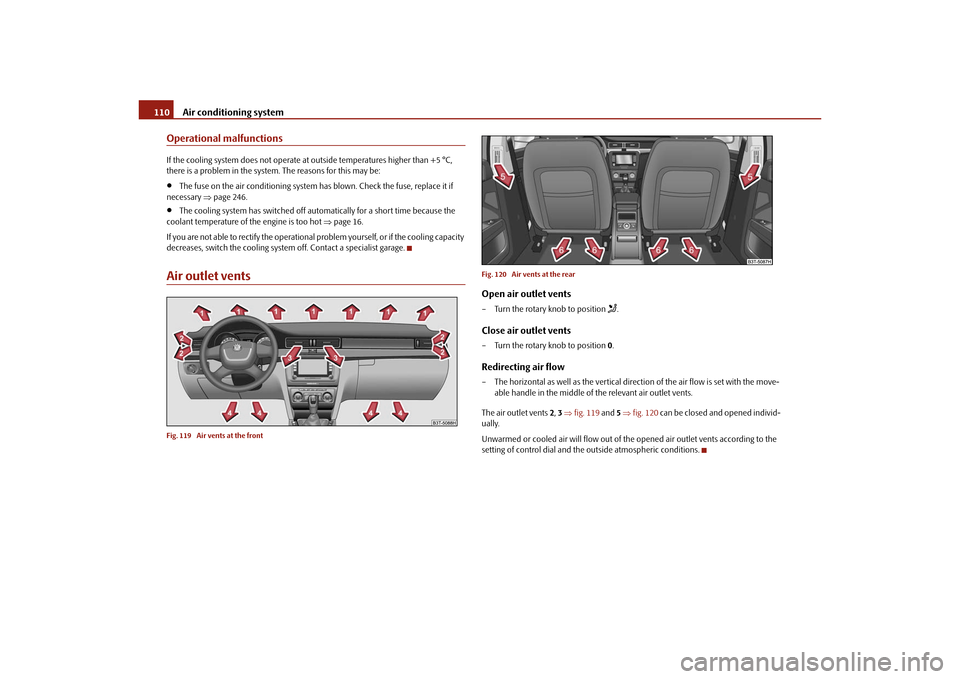
Air outlet ventsFig. 119 Air vents at the front Fig. 120 Air vents at the rear
Open air outlet vents– Turn the rotary knob to position
.
Close air outlet vents– Turn the rotary knob to position
0.Redirecting air flow– The horizontal as well as the vertical dire ction of the air flow is set with the move-
able handle in the middle of the relevant air outlet vents.
The air outlet vents 2, 3 fig. 119 and 5 fig. 120 can be closed and opened individ-
ually.
Unwarmed or cooled air will flow out of the opened air outlet vents according to the
setting of control dial and the outside atmospheric conditions.
s3fg.2.book Page 110 Friday, April 30, 2010 12:17 PM
Page 112 of 287
Air conditioning system111
Using the system
Safety
Driving Tips
General Maintenance
Breakdown assistance
Technical Data
Climatic (semi-automatic air conditioning system)Description
The Climatic is a combined coolin g and heating system. It makes it
possible to optimally control the air temperature at any season of the
year.Description of the Climatic
It is important for your safety and for your driving comfort that the Climatic is operating
properly.
The cooling only operates if button fig. 121 is pressed, and the following
conditions are met:
engine running,
outside temperature above approx. +2°C and
blower switch switched on (positions 1 to 4).
Air at a temperature of about 5°C may flow out of the vents under certain circum-
stances when the cooling system is operatin g. Lengthy and uneven distribution of the
air flow out of the vents and large differences in temperature, for example when getting
out of the vehicle, can result in chills in sensitive persons.Note
We recommend that you do not smoke in the vehicle when the recirculating air
mode is operating since the smoke which is drawn at the evaporator from the interior
of the vehicle forms deposits in the evapor ator of the air conditioning system. This
produces a permanent odour when the air co nditioning system is operating which can
only be eliminated through considerable effort and expense (replacement of
compressor).
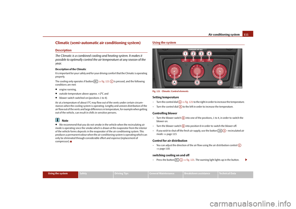
Using the systemFig. 121 Climatic: Control elementsSetting temperature– Turn the control dial fig. 121 to the right in order to increase the temperature.
– Turn the control dial to the left in order to increase the temperature.Controlling blower– Turn the blower switch into one of the po sitions, 1 to 4, in order to switch the
blower on.
– Turn the blower switch into position 0 in order to switch the blower off.
– If you wish to shut off the fresh air supply, use the button - recirculated air mode page 113.Control for air distribution– You can adjust the direction of the air flow using the air distribution control
page 110.switching cooling on and off– Press the button fig. 121 . The warning light lights up in the button.
AC
A1
AAAAABAB
A4
AC
AC
A1
s3fg.2.book Page 111 Friday, April 30, 2010 12:17 PM
Page 115 of 287
Air conditioning system
114
Climatronic* (automatic air conditioning)Description
The Climatronic system is a combination of an automatic heating, fresh
air and cooling system which provides optimal comfort for the occu-
pants of the car.The Climatronic maintains fu lly automatically a convenience temperature. This is
achieved by automatically varying the temper ature of the outflowing air, the blower
stages and the air distribution. The system also takes into account sunlight which elim-
inates the need to alter the settings manually. The automatic mode page 115
ensures maximum wellbeing of the occupants at all times of the year.
Description of Climatronic system
The cooling operates only if the following conditions are met:
engine running,
outside temperature above approx. +2°C,
switched on.
The AC compressor is switched off at a hi gh coolant temperature in order to provide
cooling at a high load of the engine.
Recommended setting for all periods of the year:
Set the desired temperature, we recommend 22°C.
Press the button fig. 122 .
Move the air outlet vents 2 and 3 so that the air flow is directed slightly upwards.
Aeration of the vehicle when ignition is switched off*
On vehicles fitted with power sliding/tilting roof with solar cells* the fresh air blower is
automatically switched over to “solar mo de” if the sun rays are sufficient after
switching off the ignition. The solar cells on the sliding/tilting roof deliver power for the
fresh air blower. This supplies the interior of the car with fresh air.
For an optimum ventilation, the air outlet vents 2 and 3 page 110, fig. 119 must be
opened.
The ventilation functions only when the sliding/tilting roof is closed.
Note
On vehicles equipped with a factory-fitted radio* or navigation*, the information of
the Climatronic is also shown on the display. This function can be switched off, see
operating instructions of the radio* or the navigation system*.Overview of the control elements
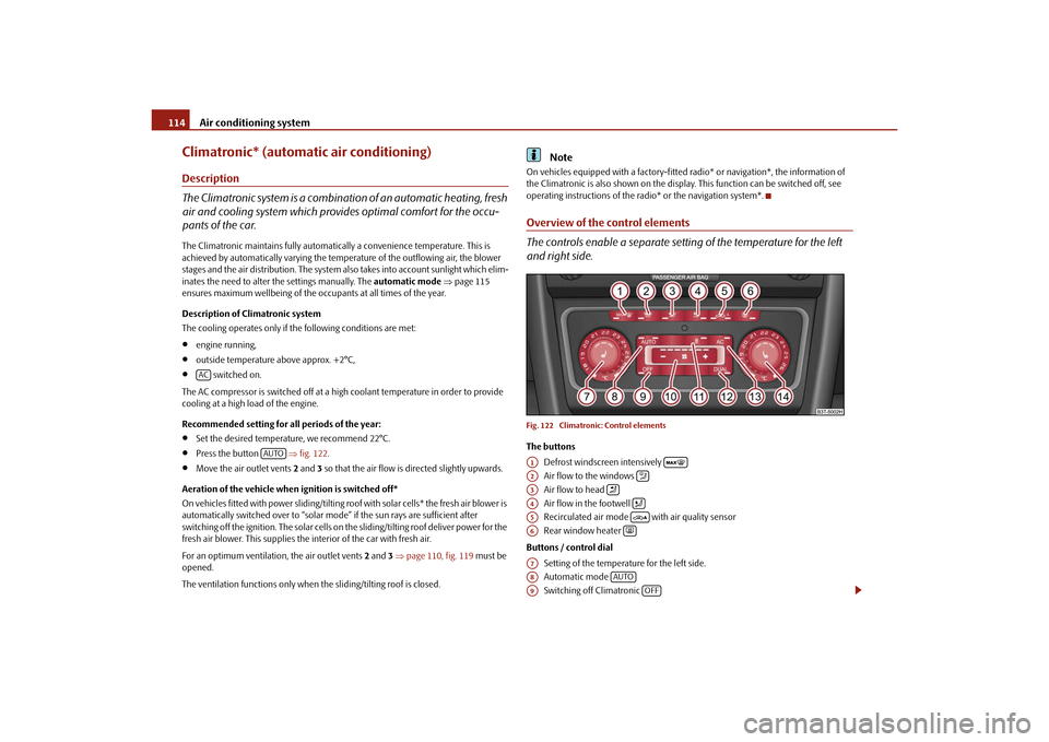
The controls enable a separate setting of the temperature for the left
and right side.Fig. 122 Climatronic: Control elementsThe buttons
Defrost windscreen intensively
Air flow to the windows
Air flow to head
Air flow in the footwell
Recirculated air mode with air quality sensor
Rear window heater
Buttons / control dial Setting of the temperature for the left side.
Automatic mode
Switching off Climatronic
AC
AUTO
A1
A2
A3
A4
A5
A6
A7A8
AUTO
A9
OFF
s3fg.2.book Page 114 Friday, April 30, 2010 12:17 PM