tow SKODA SUPERB 2010 2.G / (B6/3T) Workshop Manual
[x] Cancel search | Manufacturer: SKODA, Model Year: 2010, Model line: SUPERB, Model: SKODA SUPERB 2010 2.G / (B6/3T)Pages: 287, PDF Size: 16.59 MB
Page 131 of 287

Starting-off and Driving
130Note
Only the front parking aid operates if yo u are towing a trailer (applies only to
models which feature a factory-fitted towing device*).
If a warning signal sounds for about 3 seco nds after activating the system and there
is no obstacle close to your vehicle, this indicates a system fault. The fault is confirmed
additionally when the symbol
flashes in the button page 129, fig. 132 . Have the
fault rectified by a specialist workshop.
The sensors must be kept clean and free of ice to enable the parking aid to operate
properly.
If the parking aid is activated and the sele ctor lever of the automatic gearbox is in
the position , warning signal indicates interruption (vehicle can no longer move).
Park Assist*Description and important informationThe park assist assists you when parking in a suitable parallel parking space between
two vehicles or behind a vehicle.
The park assist automatically searches for suitable parking spaces after switching on
the ignition and when driving up to 30 km/h.
During the parking procedure the park assist only takes over the steering movements,
the pedals continue to be operated by the driver.
Function of the system is based on:
Length and depth measurement of the parking spaces when driving
Evaluation of the size of the parking space
Definition of the correct position of the vehicle for parking
Calculating the line on which the vehicle drives backwards into the parking space
Actuation of the steering force assistance, automatic spinning of the wheels of the
front axle when parking.
WARNING
The park assist does not take away th e responsability from the driver when
parking.
Pay particular attention to small children and animals as they would not be
recognised by the sensors of the parking aid.
Under certain circumstances, surfaces of certain objects and types of
clothing cannot reflect the signal of the park assist or the parking aid. Thus,
these objects or people who wear such clothing are not recognised by the
sensors of the parking aid.
The external sound source of the park assist and the parking aid can be
disruptively influenced and under unfavourable conditions, objects or people
cannot be recognised by the sensors of the parking aid.Caution
If other vehicles are parked behind or on the kurb, the park assist guides your
v ehicl e beyond the kurb or onto it. Make sure that the wheels or the wheel rims of your
vehicle are not damaged and if necessary intervene in time.
You should satisfy yourself before parking th at there is no small obstacle, such as a
rock, thin post, trailer drawbar etc., in front or behind your vehicle. Such an obstacle
might not be within the range detected by the sensors.
Under certain circumstances, surfaces or structures of certain objects such as wire
mesh fences, powder snow etc..., ca nnot be recognised by the system.
The evaluation of the parking place and the parking procedure depends on the
circumference of the wheels. The system does not function correctly if your vehicle is
mounted with wheels of no n-permissible size, snow chains or a temporary spare
wheel (in order to reach the nearest workshop). If the tyres other than those excepted
by the manufacturer are mounted, the resultin g position of the vehicle in the parking
space can differ slightly. This can be avoide d through new calibration of the system in
a specialist garage.
The accuracy of the evaluation for the parking space can be influenced by the
incorrectly determined outside temperature if the later is influenced by the thermal
radiation of the engine i.e for stop and go in a traffic jam.
AP
s3fg.2.book Page 130 Friday, April 30, 2010 12:17 PM
Page 132 of 287

Starting-off and Driving131
Using the system
Safety
Driving Tips
General Maintenance
Breakdown assistance
Technical Data
In order to avoid damaging th e sensors while cleaning with high-pressure cleaners
or steam jets, the sensors must only be directly sprayed for short periods while a
minimum distance of 10 cm must be observed.Note
A component of the park assist is the front and rear parking aid*.
The electronic stability programme (ESP) must always be switched on for the
parking procedure.
Only the front parking aid operates if yo u are towing a trailer (applies only to
models which feature a factory-fitted towing device*). This is why it is not possible to
park backwards with the help of the park assist when towing a trailer.
The sensors must be kept clean and free of ice to enable the parking aid to operate
properly.
Switch on display of the park as sist in the information display*Fig. 133 Switch on display of the park assist in the information display / information display:
Finding a suitable parking spaceSwitch on display of the park assist in the information display*– Press the button fig. 133 .
– Drive past the parking row up to maximum 30 km/h and with a distance of 0.5 m to 1.5 m fig. 133. Operate the turn signal for the driver's side if you wish to park on this side of the road.
In the information display* the search area
for the parking space is indicated on the
driver's side.
If the button is pressed above a speed of 30 km/h, the display appears in the display of
the instrument cluster as soon as you drive slower than 30 km/h.
Note
If the park assist is switched on, a yello w warning light lights up in the button.
The search for suitable parking spaces is automatic after switching on the ignition
at speeds of more than 30 km/h. Searchin g for a parking space is performed at the
same time on the driver and front passenger side.
If the sensors find a suitable parking space, they store its parameters until another
suitable parking space has been found or until a distance of 10 m had been driven after
finding the parking space. This is why it is possible to switch on the park assist after
driving past the parking space, the information on whether this parking space is suit-
able for parking appears in the information display*.
Parking with the help of the park assist and concluding the parking procedureFig. 134 Information display: the determined pa rking space with the information to drive on
and for engaging the reverse gear AA
AB
s3fg.2.book Page 131 Friday, April 30, 2010 12:17 PM
Page 134 of 287

Starting-off and Driving133
Using the system
Safety
Driving Tips
General Maintenance
Breakdown assistance
Technical Data
Park Assist finished. TCS deactivated.
The parking procedure cannot be carried ou
t because the TCS system is switched off.
TCS deactivated. Please take over steering!
The parking procedure was ended because the TCS system was switched off during the
parking procedure.
Trailer: Park Assist finished.
The parking procedure is not possible beca use the trailer is hitched and a plug is
inserted in the socket of the towing device.
Time limit exceeded. Plea se take over steering!
The parking procedure was ended because a ti me limit of 180 seconds for parking was
exceeded.
Fault: Park Assist stopped.
The parking procedure is not possible because a fault exists on the vehicle. Have the
fault rectified by a specialist workshop.
Park Assist defective. Workshop!
The parking procedure is not possible because a fault exists on the park assist. Have the
fault rectified by a specialist workshop.
Steering interv. active. Monitor area around veh.!
The park assist is active and takes over the steering movements. Observe the
surroundings and carefully drive backward s, at the same time operate the pedal.
Please take over steering! Finish parking proc. manually!
Take over the steering. End the parking procedure without using the park assist.
Speed too high! Please take over steering!
The parking procedure was ended while the speed was exceeded.
Park Assist: TCS Intervention!
Intervention of the ESP system while searching for a suitable parking place.
TCS intervention. Please take over steering!
Parking procedure is ended through the intervention of the ESP system. Park Assist: Stationary time not sufficient.
The stationary time of the vehicle was less than 1 second.
Park Assist: Speed too low.
After the ignition is switched on, the vehicle must exceed the speed of 10 km/h at least
once.
Cruise control system (CCS)*IntroductionThe cruise control system (CCS) maintains
a constant speed, more than 30 km/h (20
mph), once it has been set, without you havi ng to depress the accelerator pedal. This
is only possible within the range which is permitted by the power output and braking
power of the engine. The cruise control system makes it possible - particularly on long
journeys - for you to rest your “accelerator foot”.
WARNING
For safety reasons, the cruise control system must not be used in dense
traffic or on unfavourable ro ad surfaces (such as icy roads, slippery roads, loose
gravel) - risk of accident!
In order to prevent unintentional use of the cruise control system, always
switch off the system after use.Note
Models fitted with a manual gearbox: Alwa ys depress the clutch pedal if you switch
on the cruise control system when the gearbo x is in Neutral! Otherwise the engine can
rev up unintentionally.
The cruise control system is not able to maintain a constant speed when driving on
steep downhill sections. The weight of the vehicle increases the speed at which it
travels. One should shift down in good time to a lower gear or slow the vehicle down
by applying the foot brake.
It is not possible on vehicles fitted with an automatic gearbox to switch on the
cruise control system if the sele ctor lever is in the position P, N or R.
s3fg.2.book Page 133 Friday, April 30, 2010 12:17 PM
Page 138 of 287
Automatic gearbox DSG*137
Using the system
Safety
Driving Tips
General Maintenance
Breakdown assistance
Technical Data
Caution
The double clutch on the automatic gear box DSG is equipped with an overload
protection. If you make use of the uphill function on a vehicle which is stationary or
driving slowly uphill, it will result in an increase of thermal stress of the clutches.
In the event that they overheat, the symbol
and a warning page 36 appear in
the information display*. In such a case bring the vehicle to a stop, switch off the
engine and wait until the warning light and the warning go out - risk of gearbox
damage! You can continue the trip as soon as the symbol and the warning go out.
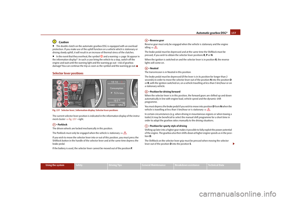
Selector lever positionsFig. 137 Selector lever / information display: Selector lever positionsThe current selector lever position is indica ted in the information display of the instru-
ment cluster fig. 137 - right.
- Parklock
The driven wheels are locked me chanically in this position.
The Parklock must only be engage d when the vehicle is stationary .
If you wish to move the selector lever into or out of this position, you must press the
Shiftlock button in the handle of the select or lever and at the same time depress the
brake pedal.
If the battery is used, the selector lever cannot be moved out of the position P. - Reverse gear
Reverse gear must only be engaged when the vehicle is stationary and the engine
idling .
The brake pedal must be depressed and at the same time the Shiftlock must be
pressed, if you wish to obtain the selector lever positions R, P or N.
When the ignition is switched on an d the selector lever is in position R, the reverse
lights will come on.
- Neutral
The transmission is in Neutral in this position.
The brake pedal must be depressed (if the le ver is in its position for longer than 2
seconds) in order to move the se lector lever out of the position N into the position D
or R, with the ignition switched on, on a vehicle travelling at less than 5 km/hour or on
a stationary vehicle.
- Position for driving forward
When the selector lever is in this position, the forward gears are shifted up and down
automatically in line with engine load, vehicle speed and the dynamic shift
programme.
You must depress the brake pedal if you wish to move into position D from N when the
vehicle is travelling at less th an 5 km/hour or is stationary .
In certain circumstances (e.g. when driving in mountainous regions or when towing a
trailer) it may be beneficial to select th e manual shift programme for a short time in
order to adapt the gearbox ratios manually to the driving situations.
- Position for sporty style of driving
Shifting up later into a higher gear makes it possible to fully exploit the power potential
of the engine. The gearbox also then shifts down at higher engine speeds as in the posi-
tion D.
The Shiftlock on the selector lever grip must be pressed when moving the selector
lever out of the position D into the position S.AP
ARANADAS
s3fg.2.book Page 137 Friday, April 30, 2010 12:17 PM
Page 141 of 287
Automatic gearbox DSG*
140
Shifting down gears
– Press the left rocker switch page 139, fig. 139 for the multifunction steering
wheel.Temporarily switching over to manual shifting– If the selector lever is in position D or S, press the left rocker switch or the right
rocker switch for the multifunction steering wheel.
– If the rocker switches or are not pressed for some time, the manual shifting switches off. You can also switch off the temporary switch over to manual shifting
by pressing the right rocker switch for more than 1 second.Emergency programme
An emergency programme exists in th e event of a fault in the system.The gearbox operates in a corresponding emergency programme if there are func-
tional faults in the gearbox electronics. This is indicated by all of the segments in the
display lighting up or going out.
A functional fault can have the following effect:
The gearbox only shifts into certain gears.
The reverse gear R cannot be used.
The manual shift programme (Tiptronic) is switched off in the emergency mode.
If the gearbox has switch ed over to emergency mode, drive to the nearest
specialist garage in order to have the fault rectified.
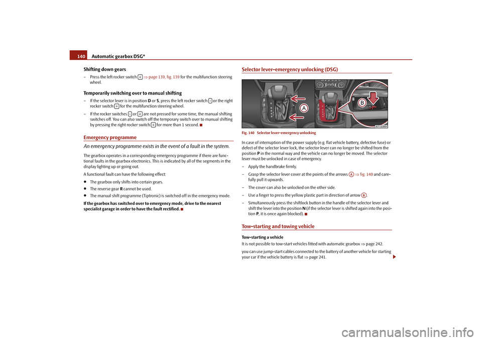
Selector lever-emergency unlocking (DSG)Fig. 140 Selector lever-emergency unlockingIn case of interruption of the power supply (e.g. flat vehicle battery, defective fuse) or
defect of the selector lever lock, the select or lever can no longer be shifted from the
position P in the normal way and the vehicle ca n no longer be moved. The selector
lever must be unlocked in case of emergency.
– Apply the handbrake firmly.
– Grasp the selector lever cover at the points of the arrows fig. 140 and care-
fully pull it upwards.
– The cover can also be unlocked on the other side.
– Use a finger to press the yellow pl astic part in direction of arrow .
– Simultaneously press the shiftlock button in the handle of the selector lever and
shift the lever into the position N (if the selector lever is shifted again into the posi-
tion P, it is once again blocked).Tow-starting and towing vehicle Tow-starting a vehicle
It is not possible to tow-start ve hicles fitted with automatic gearbox page 242.
you can use jump-start cables connected to the battery of another vehicle for starting
your car if the vehicle battery is flat page 241.
+
-
+
-
+
+
AA
AB
s3fg.2.book Page 140 Friday, April 30, 2010 12:17 PM
Page 142 of 287

Automatic gearbox DSG*141
Using the system
Safety
Driving Tips
General Maintenance
Breakdown assistance
Technical Data
Towing a vehicle
Please pay attention to the following information if it comes necessary to tow-in your
car
page 242.
s3fg.2.book Page 141 Friday, April 30, 2010 12:17 PM
Page 166 of 287
Seat belts165
Using the system
Safety
Driving Tips
General Maintenance
Breakdown assistance
Technical Data
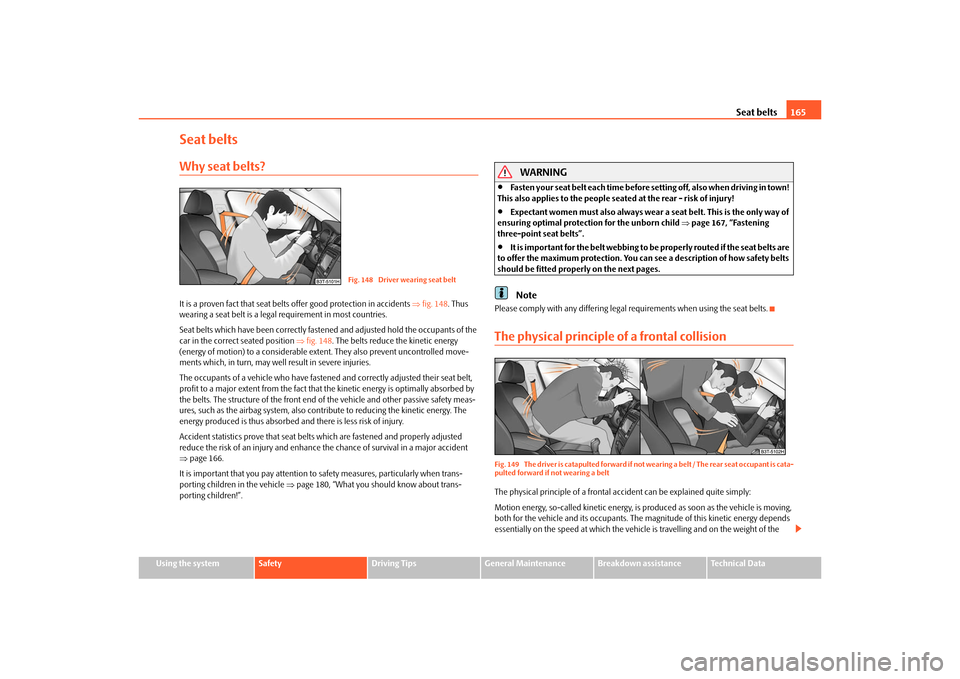
Seat beltsWhy seat belts?It is a proven fact that seat belt s offer good protection in accidents fig. 148 . Thus
wearing a seat belt is a legal requirement in most countries.
Seat belts which have been correctly fasten ed and adjusted hold the occupants of the
car in the correct seated position fig. 148 . The belts reduce the kinetic energy
(energy of motion) to a considerable exte nt. They also prevent uncontrolled move-
ments which, in turn, may well result in severe injuries.
The occupants of a vehicle who have fastened and correctly adjusted their seat belt,
profit to a major extent from the fact that the kinetic energy is optimally absorbed by
the belts. The structure of the front end of the vehicle and other passive safety meas-
ures, such as the airbag system, also cont ribute to reducing the kinetic energy. The
energy produced is thus absorbed and there is less risk of injury.
Accident statistics prove that seat belts which are fastened and properly adjusted
reduce the risk of an injury and enhance the chance of survival in a major accident
page 166.
It is important that you pay attention to safety measures, particularly when trans-
porting children in the vehicle page 180, “What you should know about trans-
porting children!”.
WARNING
Fasten your seat belt each time before setting off, also when driving in town!
This also applies to the people seated at the rear - risk of injury!
Expectant women must also always wear a seat belt. This is the only way of
ensuring optimal protection for the unborn child page 167, “Fastening
three-point seat belts”.
It is important for the belt webbing to be properly routed if the seat belts are
to offer the maximum protection. You can see a description of how safety belts
should be fitted properly on the next pages.Note
Please comply with any differing legal requirements when using the seat belts.The physical principle of a frontal collisionFig. 149 The driver is catapulted forward if not wearing a belt / The rear seat occupant is cata-
pulted forward if not wearing a beltThe physical principle of a frontal a ccident can be explained quite simply:
Motion energy, so-called kinetic energy, is produced as soon as the vehicle is moving,
both for the vehicle and its occupants. The magnitude of this kinetic energy depends
essentially on the speed at which the vehicl e is travelling and on the weight of the
Fig. 148 Driver wearing seat belt
s3fg.2.book Page 165 Friday, April 30, 2010 12:17 PM
Page 190 of 287
Intelligent Technology189
Using the system
Safety
Driving Tips
General Maintenance
Breakdown assistance
Technical Data
General
The TCS makes it much easier, and sometimes at
all possible, to start off, accelerate and
climb a steep hill when th e conditions of the road surface are unfavourable.
Operating principle
The TCS switches on automatically when th e engine is started and then conducts a
self-test. The system monitors the speeds of the driven wheels with the aid of the ABS
sensors. If the wheels are spinning, the force transmitted to the road surface is auto-
matically adapted by reducing the engine speed. The system operates at all speeds.
The TCS operates in combination with the ABS page 191. The TCS will not function
if a fault exists in the ABS system.
The TCS warning light lights up in the instru ment cluster when there is a fault on the
TCS
page 33.
During an intervention of the system, the TCS warning light
flashes in the instru-
ment cluster page 33.
Switching off
You can switch the TCS off and on again as you wish by pressing the button
page 188, fig. 171 . The TCS warning light lights up in the instrument cluster when
the system is switched off
page 33.
The TCS should normally always be switched on. It may be good practice in certain
exceptional cases, such as when you wish to have wheel slip, to switch off the system.
Examples:
when driving with snow chains,
when driving in deep snow or on a loose surface,
when it is necessary to rock a vehicle when it has become stuck.
then you should switch on the TCS again.
WARNING
You should always adjust your style of driving to the conditions of the road
surface and the traffic situation. The increased safety offered must not tempt
you to take greater risks than otherwise - risk of an accident!
Note
All four wheels must be fitted with the same tyres in order to achieve problem-free
operation of the TCS. Differing rolling circumferences of the tyres can lead to an unde-
sirable reduction in the engine output.
Changes to vehicle (e.g. on engine, on the brakes, on chassis or another combina-
tion of tyres and wheels) can influence the function of the TCS page 234, “Accesso-
ries, changes and replacement of parts”.
Active driver-steering recommendation (DSR)*Vehicles with ESP and ABS ar e equipped with active driver-steering recommendation
(DSR).
This function indicates to the driver in crit ical situations a steering recommendation in
order to stabilise the vehicle. The active driver-steering recommendation is activated,
for example, on the right and left vehicle si de when braking sharply on different road
surfaces.
WARNING
Even with this additional function the vehicle cannot steer itself! The driver is
furthermore responsible for the steering of the vehicle!BrakesWhat has a negative effect on braking efficiency?Wear-and-tear
Wear-and-tear to the brake pa ds is greatly dependent on the operating conditions of
the vehicle and your style of driving. Particularly if you drive a great deal in towns and
over short distances or if you adopt a sporty style of driving, it may be necessary to
have the thickness of the brake pads insp ected at a specialist garage between the
service inspections.
Wet roads or road salt
There may be a certain delay before the brakes take full effect un der certain conditions
such as when driving through water, during heavy rain showers or after the vehicle has
s3fg.2.book Page 189 Friday, April 30, 2010 12:17 PM
Page 193 of 287

Intelligent Technology
192
Uphill Start Assist*The uphill start assist makes it easier to start off on steep hills. The system assists a start
off by holding the brake pressure produced by the brake pedal actuation for approx. 2
seconds after releasing the brake pedal. The driver can therefore move his foot from
the brake pedal to the accelerator pedal and start off on the slope, without having to
actuate the handbrake. The brake pressure drops gradually the more you operate the
accelerator pedal. If the vehicle does not start off within 2 seconds, it starts to roll back.
The uphill start assist is active as of a 5 % slope, if the driver door is closed. It is always
active on slopes when in forward or reverse start off. When driving downhill, it is
inactive.Electromechanical power steeringThe power steering enables you to steer the vehicle with le ss physical force.
With the electromechanical power steering , the steering assist is automatically
adapted to the speed and to the steering angle.
It is still possible to fully steer the vehicle if the power steering fails or if the engine is
not running (vehicle being towed in). The only difference is that greater physical effort
is required.
If there is a fault in the power steering, the warning light
or lights up in the instru-
ment cluster page 31.
WARNING
Contact your specialist garage if the power steering is defective.
Tyre pressure monitoring system*The tyre pressure monitoring system compares with the aid of the ABS sensors the
speed and also the rolling circumference of the individual wheels. If the rolling circum-
ference of a wheel is changed, the warning light
lights up in the instrument cluster
page 34 and an audible signal sounds. The rolling circumference of the tyre can
change if:
the tyre inflation pressure is too low,
the structure of the tyre is damaged,
the vehicle is loaded on one side,
the wheels of an axle are loaded heavily (e.g. when towing a trailer or when driving
uphill or downhill),
snow chains are mounted,
the temporary spare wheel is mounted,
one wheel per axle was changed.
Basic setting of the system
After changing the tyre inflation pressures, after changing one or several wheels, the
position of a wheel on the vehicle (e.g. ex changing the wheels between the axles) or
when the warning light lights up while drivin g, a basic setting of the system must be
carried out as follows.
Inflate all tyres to the specified inflation pressure page 228.
Switch on the ignition.
Fig. 172 Button for setting the tyre
inflation pressure control value
s3fg.2.book Page 192 Friday, April 30, 2010 12:17 PM
Page 196 of 287
Driving and the Environment195
Using the system
Safety
Driving Tips
General Maintenance
Breakdown assistance
Technical Data
Driving and the EnvironmentThe first 1 500 kilometres and then afterwardsA new engine
The engine has to be run in during the first 1 500 kilometres.Up to 1 000 kilometres– Do not drive faster than 3/4 of the maximum speed of the gear in use, that is 3/4 of
the maximum permissi ble engine speed.
– Do not use full throttle.
– Avoid high engine revolutions.
– Do not tow a trailer.From 1 000 up to 1 500 kilometres– Increase the power output of the engine gradually up to the full speed of the gear
engaged, that is up to the maxi mum permissible engine revolutions.
During the first operating hours the engine ha s higher internal friction than later until
all of the moving parts have harmonized. Th e driving style which you adopt during the
first approx.1 500 kilometres plays a decisive part in the success of running in your
vehicle.
You should not drive at unnecessarily high engine revolutions even after the
running-in period is complete . The maximum permissible en gine speed is marked by
the beginning of the red zone on the scale of the revolutions counter. Shift up into the
next higher gear on a vehi cle fitted with manual gear box before the red zone is
reached. Extremely high engine revolutions are automatically governed, by the way.
For a vehicle fitted with a manual gearbox the converse situation also applies: Do not
drive at engine revolutions which are too low. Shift down as soon as the engine is no
longer running smoothly.
Caution
All the speed and engine revolution figures ap ply only when the engine is at its normal
operating temperature. Never rev up an engine which is cold, neither when the vehicle
is stationary nor when driving in individual gears.
For the sake of the environment
Not driving at unnecessari ly high engine revolutions and shifting to a higher gear as
early as possible are ways to minimise fu el consumption and operating noise levels
and protects the environment.New tyresNew tyres have to be “run in” since they do not offer optimal grip at first. You should
take account of this fact for the first 500 kilometres and drive particularly carefully.New brake padsAllow for the fact that new brake pads do no t achieve their full braking efficiency until
approximately 200 kilometres. New brake pads must be first “run in” before they
develop their optimal friction force. You ca n, however, compensate for this slightly
reduced braking force by increasing the pressure on the brake pedal.
This guideline also applies to any new brake pads installed at a future date.
During the running-in pe riod, you should avoid excessive stresses on the brakes. This
includes, for example, violent braking, part icularly from very high speeds, and also
when crossing mountain passes.
s3fg.2.book Page 195 Friday, April 30, 2010 12:17 PM