engine coolant SKODA SUPERB 2010 2.G / (B6/3T) Owner's Manual
[x] Cancel search | Manufacturer: SKODA, Model Year: 2010, Model line: SUPERB, Model: SKODA SUPERB 2010 2.G / (B6/3T)Pages: 287, PDF Size: 16.59 MB
Page 4 of 287
Contents3
Using the system
Safety
Driving Tips
General Maintenance
Breakdown assistance
Technical Data
ContentsLayout of this Owner's Manual
(explanations)
. . . . . . . . . . . . . . . . . . . . . . . . . .
Using the system
. . . . . . . . . . . . . . . . . . . . . .
Cockpit
. . . . . . . . . . . . . . . . . . . . . . . . . . . . . . . . . . . . . . . .
Overview . . . . . . . . . . . . . . . . . . . . . . . . . . . . . . . . . . . .
The brief instruction
. . . . . . . . . . . . . . . . . . . . . . . . . .
Basic functions and important information . . . . .
Instruments and warning lights
. . . . . . . . . . . . . . .
Overview of the instrument cluster . . . . . . . . . . . . .
Engine revolutions counter . . . . . . . . . . . . . . . . . . . .
Speedometer . . . . . . . . . . . . . . . . . . . . . . . . . . . . . . . .
Coolant temperature gauge . . . . . . . . . . . . . . . . . . .
Fuel gauge . . . . . . . . . . . . . . . . . . . . . . . . . . . . . . . . . . .
Counter for distance driven . . . . . . . . . . . . . . . . . . .
Service Interval Display . . . . . . . . . . . . . . . . . . . . . . .
Digital clock . . . . . . . . . . . . . . . . . . . . . . . . . . . . . . . . . .
Shift recommendation for changing gears* . . . . .
Multi-functional indicator (onboard computer)*
Information display* . . . . . . . . . . . . . . . . . . . . . . . . . .
Auto Check Control* . . . . . . . . . . . . . . . . . . . . . . . . . .
Warning lights . . . . . . . . . . . . . . . . . . . . . . . . . . . . . . . .
Unlocking and locking
. . . . . . . . . . . . . . . . . . . . . . . .
Key . . . . . . . . . . . . . . . . . . . . . . . . . . . . . . . . . . . . . . . . . .
Changing the battery in the remote control key .
Electronic immobiliser . . . . . . . . . . . . . . . . . . . . . . . .
Child safety lock . . . . . . . . . . . . . . . . . . . . . . . . . . . . . .
Central locking system . . . . . . . . . . . . . . . . . . . . . . . .
Remote control . . . . . . . . . . . . . . . . . . . . . . . . . . . . . . .
Description . . . . . . . . . . . . . . . . . . . . . . . . . . . . . . . . . .
Unlocking and locking car . . . . . . . . . . . . . . . . . . . . .
Synchronisation of the remote control . . . . . . . . . .
Anti-theft alarm system* . . . . . . . . . . . . . . . . . . . . . . Power windows . . . . . . . . . . . . . . . . . . . . . . . . . . . . . . .
Electric sliding/tilting roof* . . . . . . . . . . . . . . . . . . . . .
Panoramic sliding roof* (Combi) . . . . . . . . . . . . . . .
Lights and Visibility
. . . . . . . . . . . . . . . . . . . . . . . . . . . .
Lights . . . . . . . . . . . . . . . . . . . . . . . . . . . . . . . . . . . . . . . .
Interior lighting . . . . . . . . . . . . . . . . . . . . . . . . . . . . . . .
Luggage compartment light (Combi) . . . . . . . . . . . .
Visibility . . . . . . . . . . . . . . . . . . . . . . . . . . . . . . . . . . . . . .
Windshield wiper and wash system . . . . . . . . . . . . .
Rear-view mirror . . . . . . . . . . . . . . . . . . . . . . . . . . . . . .
Exterior mirror . . . . . . . . . . . . . . . . . . . . . . . . . . . . . . . .
Exterior mirror with entry lighting* . . . . . . . . . . . . .
Automatic dimming exterior mirror* . . . . . . . . . . . .
Seats and Stowage
. . . . . . . . . . . . . . . . . . . . . . . . . . . . .
Front seats . . . . . . . . . . . . . . . . . . . . . . . . . . . . . . . . . . . .
Adjusting front seats electrically* . . . . . . . . . . . . . . .
Head restraints . . . . . . . . . . . . . . . . . . . . . . . . . . . . . . . .
Middle rear head restraint . . . . . . . . . . . . . . . . . . . . .
Rear seats . . . . . . . . . . . . . . . . . . . . . . . . . . . . . . . . . . . .
luggage compartment . . . . . . . . . . . . . . . . . . . . . . . . .
Variable loading floor in the luggage compartment*
(Combi) . . . . . . . . . . . . . . . . . . . . . . . . . . . . . . . . . . . . . .
Net partition* (Combi) . . . . . . . . . . . . . . . . . . . . . . . .
The roof rack* . . . . . . . . . . . . . . . . . . . . . . . . . . . . . . . .
Cup holder . . . . . . . . . . . . . . . . . . . . . . . . . . . . . . . . . . .
Ashtray . . . . . . . . . . . . . . . . . . . . . . . . . . . . . . . . . . . . . . .
Cigarette lighter*, power sockets . . . . . . . . . . . . . . .
Storage compartments . . . . . . . . . . . . . . . . . . . . . . . .
Air conditioning system
. . . . . . . . . . . . . . . . . . . . . . .
Introduction . . . . . . . . . . . . . . . . . . . . . . . . . . . . . . . . . .
Air outlet vents . . . . . . . . . . . . . . . . . . . . . . . . . . . . . . . .
Climatic (semi-automatic air conditioning system)
Climatronic* (automatic air conditioning) . . . . . . .
Auxiliary heating (auxiliary heating and ventilation)*
Starting-off and Driving
. . . . . . . . . . . . . . . . . . . . . . .
Setting steering wheel position . . . . . . . . . . . . . . . .
Ignition lock . . . . . . . . . . . . . . . . . . . . . . . . . . . . . . . . . .
Starting the engine . . . . . . . . . . . . . . . . . . . . . . . . . . . .
KESSY system* . . . . . . . . . . . . . . . . . . . . . . . . . . . . . . .
Parking aid* . . . . . . . . . . . . . . . . . . . . . . . . . . . . . . . . . .
Park Assist* . . . . . . . . . . . . . . . . . . . . . . . . . . . . . . . . . .
Cruise control system (CCS)* . . . . . . . . . . . . . . . . . .
Automatic gearbox DSG*
. . . . . . . . . . . . . . . . . . . . .
Automatic gearbox DSG* . . . . . . . . . . . . . . . . . . . . . .
Communication
. . . . . . . . . . . . . . . . . . . . . . . . . . . . . . .
Multifunction steering wheel* . . . . . . . . . . . . . . . . .
Mobile phones and two-way radio systems . . . . .
Universal telephone preinstallation GSM II* . . . . .
Voice control . . . . . . . . . . . . . . . . . . . . . . . . . . . . . . . . .
Music playback via Bluetooth® . . . . . . . . . . . . . . . .
Universal telephone preinstallation GSM IIl* . . . .
Voice control . . . . . . . . . . . . . . . . . . . . . . . . . . . . . . . . .
Connection to the internet . . . . . . . . . . . . . . . . . . . .
Music playback via Bluetooth® . . . . . . . . . . . . . . . .
Multimedia . . . . . . . . . . . . . . . . . . . . . . . . . . . . . . . . . .
Safety
. . . . . . . . . . . . . . . . . . . . . . . . . . . . . . . . . . . . . . .
Passive Safety
. . . . . . . . . . . . . . . . . . . . . . . . . . . . . . . . .
Basic information . . . . . . . . . . . . . . . . . . . . . . . . . . . . .
Correct seated position . . . . . . . . . . . . . . . . . . . . . . .
Seat belts
. . . . . . . . . . . . . . . . . . . . . . . . . . . . . . . . . . . . . .
Why seat belts? . . . . . . . . . . . . . . . . . . . . . . . . . . . . . . .
The physical principle of a frontal collision . . . . . .
Important safety information regarding the use of seat
belts . . . . . . . . . . . . . . . . . . . . . . . . . . . . . . . . . . . . . . . . .
How are seat belts correctly fastened? . . . . . . . . . .
6799101015151516161617171819192324273737373838384949495050
52555760606770717377777878808081848485879295979899100100109109110111114117
121121121122125128130133136136142142145145150151152157158158159161161161162165165165166167
s3fg.2.book Page 3 Friday, April 30, 2010 12:17 PM
Page 16 of 287
Instruments and warning lights15
Using the system
Safety
Driving Tips
General Maintenance
Breakdown assistance
Technical Data
Instruments and warning lightsOverview of the instrument cluster
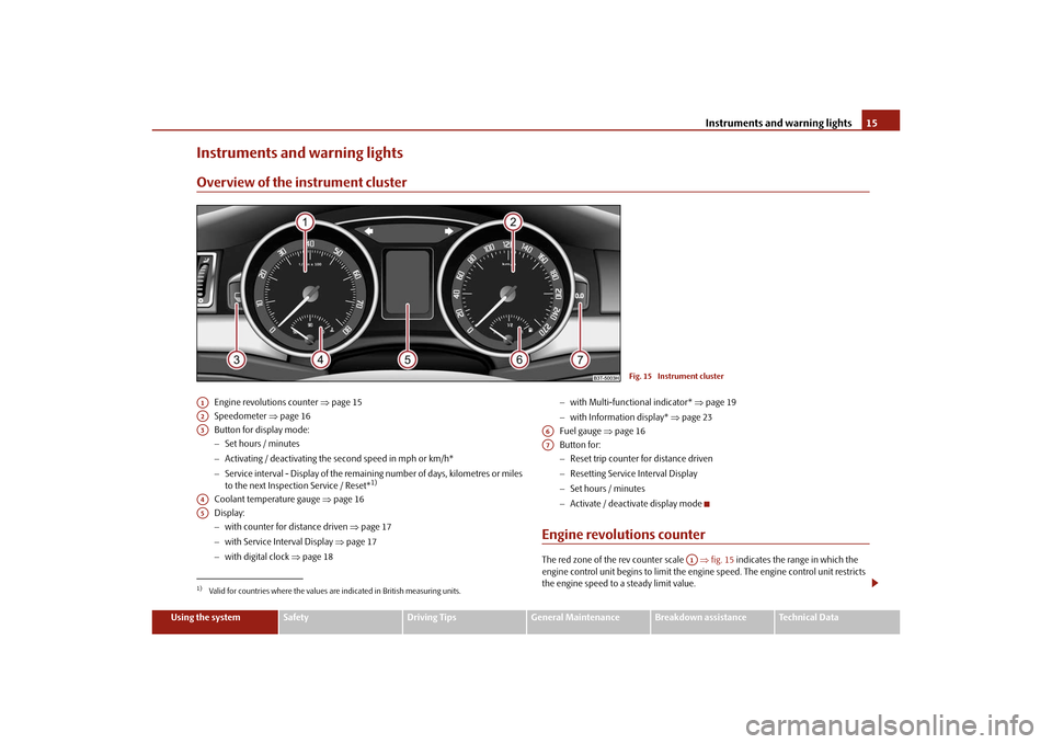
Engine revolutions counter page 15
Speedometer page 16
Button for display mode:
Set hours / minutes
Activating / deactivating the second speed in mph or km/h*
Service interval - Display of the remaining number of days, kilometres or miles
to the next Inspection Service / Reset*
1)
Coolant temperature gauge page 16
Display:
with counter for distance driven page 17
with Service Interval Display page 17
with digital clock page 18
with Multi-functional indicator* page 19
with Information display* page 23
Fuel gauge page 16
Button for:
Reset trip counter for distance driven
Resetting Service Interval Display
Set hours / minutes
Activate / deactivate display mode
Engine revolutions counterThe red zone of the rev counter scale fig. 15 indicates the range in which the
engine control unit begins to limit the engi ne speed. The engine control unit restricts
the engine speed to a steady limit value.
Fig. 15 Instrument cluster
1)Valid for countries where the values are indicated in British measuring units.A1A2A3A4A5
A6A7
A1
s3fg.2.book Page 15 Friday, April 30, 2010 12:17 PM
Page 17 of 287
Instruments and warning lights
16
Shift into the next higher gear or select th e selector lever position D of the automatic
gearbox before reaching the red zone of the rev counter scale.
Avoid high engine speeds du ring the driving time and before the engine has been
warmed up to operating temperature page 195.
For the sake of the environment
Shifting up early helps you sa ve fuel and reduce the operating noise of your vehicle.SpeedometerWarning against excessive speeds*
An acoustic warning signal will sound when the vehicle speed exceeds 120 kilometres
per hour. The acoustic warning signal will switch off again when the vehicle speed goes
below this speed limit.
Note
This function is only valid for some countries.Coolant temperature gaugeThe coolant temperature gauge page 15, fig. 15 operates only when the ignition
is switched on.
In order to avoid any damage to the engine, please pay attention to the following notes
regarding the temperature ranges:
Cold range
If the pointer is in the left-hand area of the scale it means that the engine has not yet
reached its operating temperatur e. Avoid running at high engine speeds, at full throttle
and at severe engine loads.
The operating range
The engine has reached its operating temper ature as soon as the pointer moves into
the mid-range of the scale. The pointer may also move further to the right at high engine loads and high outside temperatures. This is not critical provided the warning
symbol
in the instrument cl
uster does not flash.
If the symbol in the instrument cluster flashes it means that either the coolant
temperature is too high or the coolant level is too low. Observe the guidelines
page 32, “Coolant temperature/ Coolant quantity ”.
WARNING
Pay attention to the warning notes page 216, “Working in the engine
compartment” before opening the bonn et and inspecting the coolant level.
Caution
Additional headlights and other attached components in front of the fresh air inlet
impair the cooling efficiency of the coolant. There is then a risk of the engine over-
heating at high outside temper atures and high engine loads.Fuel gaugeThe fuel gauge page 15, fig. 15 only operates when the ignition is switched on.
The fuel tank has a capacity of about 60 litres. The warning symbol
in the instrument
cluster lights up when the pointer reaches the reserve marking. There are now about
10.5 litres of fuel remaining in the ta nk. This symbol is a reminder for you, that you
must refuel .
The following will be displayed in the information display*: Please refuel!
An audible signal sounds as an additional warning signal.
Caution
Never run the fuel tank completely empty! An irregular supply of fuel can lead to irreg-
ular engine running. Unburnt fuel may get into the exhaust system and damage the
catalytic converter.
A4
A6
s3fg.2.book Page 16 Friday, April 30, 2010 12:17 PM
Page 29 of 287
Instruments and warning lights
28
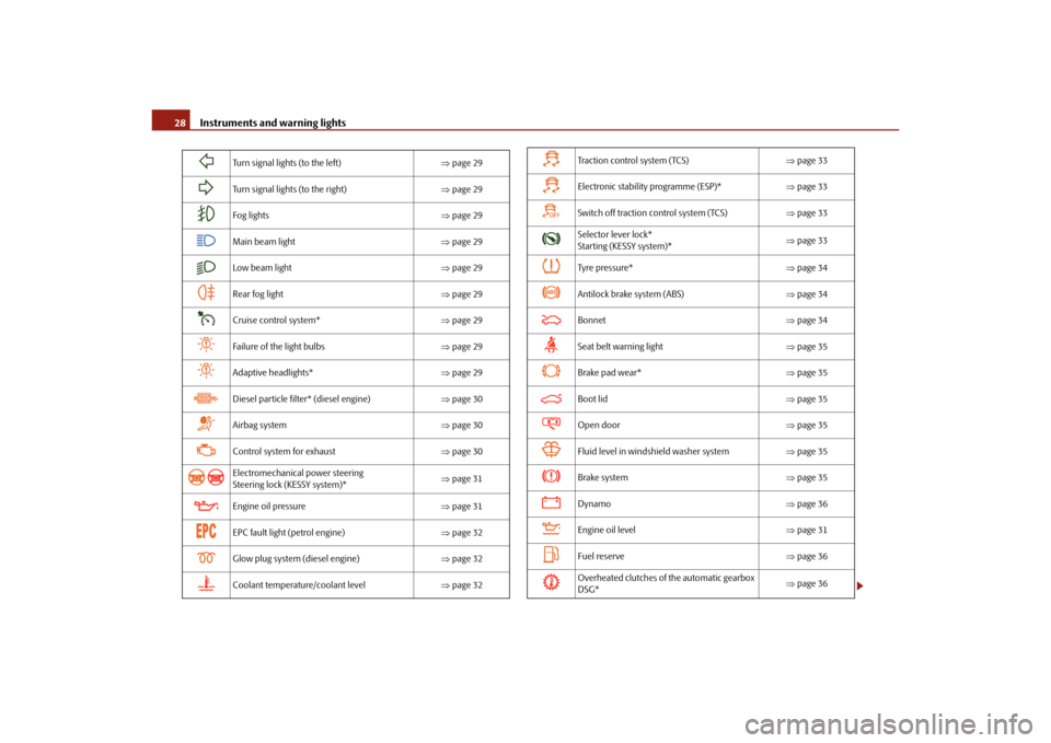
Turn signal lights (to the left) page 29
Turn signal lights (to the right) page 29
Fog lights page 29
Main beam light page 29
Low beam light page 29
Rear fog light page 29
Cruise control system* page 29
Failure of the light bulbs page 29
Adaptive headlights* page 29
Diesel particle filter* (diesel engine) page 30
Airbag system page 30
Control system for exhaust page 30
Electromechanical power steering
Steering lock (KESSY system)*
page 31
Engine oil pressure page 31
EPC fault light (petrol engine) page 32
Glow plug system (diesel engine) page 32
Coolant temperature/coolant level page 32
Tra c t i o n c o n t r o l s y s t e m ( TC S ) page 33
Electronic stability programme (ESP)* page 33
Switch off traction control system (TCS) page 33
Selector lever lock*
Starting (KESSY system)*
page 33
Tyre pressure* page 34
Antilock brake system (ABS) page 34
Bonnet page 34
Seat belt warning light page 35
Brake pad wear* page 35
Boot lid page 35
Open door page 35
Fluid level in windshield washer system page 35
Brake system page 35
Dynamo page 36
Engine oil level page 31
Fuel reserve page 36
Overheated clutches of the automatic gearbox
DSG*
page 36
s3fg.2.book Page 28 Friday, April 30, 2010 12:17 PM
Page 33 of 287
Instruments and warning lights
32
The warning light will go out if the bonnet is le ft open for more than 30 seconds. If no
engine oil has been replenished, the warning light will come on again after driving
about 100 km.
Warning light
flashes
A fault on the engine oil level sensor is indicated additionally by an audible signal and
the warning light coming on several times after the ignition has been switched on.
In this case have the engine inspected without delay by a specialist garage.
The following text will be displayed in the information display*:
Oil sensor. Workshop!
EPC fault light
(petrol engine)
The
(Electronic Power Control) warning light comes on for a few seconds when the
ignition is switched on.
If the warning light
does not go out or lights up after starting the engine, a fault
exists in the engine control. The engine management system selects an emergency
programme which enables you to drive to the nearest specialist garage by adopting a
gentle style of driving.
The following text will be displayed in the information display*:
Engine fault: Workshop!
Glow plug system
(diesel engine)
The warning light
lights up for a cold engine when switching on the ignition (pre-
heat position) 2 page 121. Start the engine after the indicator light goes out.
The glow plug indicato r light will come on for about 1 second if the engine is at a
normal operating temperature or if the outside temperature is above +5°C. This
means that you can start the engine right away.
There is a fault in the glow plug system if the warning light
does not come on at
all or lights up continuously . Contact a specialist garage as soon as possible to obtain
assistance. If the
warning light
begins to flash while driving, a fault exists in the engine control.
The engine management system selects an emergency programme which enables you
to drive to the nearest specialist garage by adopting a gentle style of driving.
The following text will be displayed in the information display*:
Engine fault: Workshop!
Coolant temperature/ Coolant quantity
The warning light comes on for a few seconds
4) when the ignition is switched on.
The coolant temperature is too high or the coolant level too low if the warning light
does not go out or flashes while driving.
3 peeps sound as an additional warning signal.
In this case stop and switch the engine off and check the coolant level; top up the
coolant as necessary.
Do not continue your journey if for some reason it is not possible under the condi-
tions prevailing to top up with coolant. Keep the engine switched off and obtain
professional assistance from a specialist garage, otherwise it could lead to severe
engine damage.
If the coolant is within the specified range, the increased temperature may be caused
by an operating problem at the coolant fan. Check the fuse for the coolant fan, replace
it if necessary page 247, “Fuse assignment in engi ne compartment - version 1” or
page 248, “Fuse assignment in engine compartment - version 2”.
Do not continue driving if the warning light does not go off although the fluid is at the
correct level and also the fuse of the fan is in proper order. Contact a specialist garage
to obtain assistance.
Please refer to the following guidelines page 219, “Cooling system”.
The following text will be displayed in the information display*: Check coolant! Owner's manual!
4)The warning light on vehicles fitted with information display does not come on after switching
the ignition on, but only if the coolant temperature is too high or the coolant level is too low.
s3fg.2.book Page 32 Friday, April 30, 2010 12:17 PM
Page 34 of 287
Instruments and warning lights33
Using the system
Safety
Driving Tips
General Maintenance
Breakdown assistance
Technical Data
WARNING
If you must stop for technical reasons, then park the vehicle at a safe
distance from the traffic and switch off the engine and switch on the hazard
warning light system page 66.
Take care when opening the coolant expa nsion bottle. If the engine is hot,
the cooling system is pressurized - risk of scalding! It is best to allow the engine
to cool down before removing the cap.
Do not touch the coolant fan The coolant fan may switch on automatically
even if the ignition is off.
Traction control system (TCS)
The warning light
comes on for a few seconds when the ignition is switched on.
The warning light flashes when a control cycle is activated while driving.
The warning light lights up permanentl y if there is a fault in the system.
The fact that the TCS system operates together with the ABS means that the TCS
warning light will also come on if the ABS system is not operating properly.
If the warning light comes on immediately after starting the engine, the TCS system
can be switched off for technical reasons. In this case, the TCS system can be switched
on again by switching the ignition on and off. If the warning light goes out, the TCS
system is fully functional again.
Further information about the TCS page 188, “Traction control system (TCS)”.
Note
If the battery has been disconnected and reconnected, the warning light
comes on
after switching on the ignition. The warning light must go out after driving a short
distance.
Switch off traction control system (TCS)
The TCS system is switched off by pressing the button page 188, fig. 171 and the
warning light
lights up.
Electronic stability programme (ESP)*
The warning light
comes on for a few seconds when the ignition is switched on.
When the ESP helps to stabilise the vehicle, the warning light
flashes in the informa-
tion display.
The ESP system cannot be switched off, only the TCS system can be switched off by
pressing the button page 187, fig. 170, the warning light
lights up.
The warning light lights up permanently if there is a fault in the ESP system.
The fact that the ESP system operates together with the ABS means that the ESP
warning light will also come on if the ABS system is not operating properly.
If the warning light
comes on immediately after starting the engine, the ESP system
can be switched off for technical reasons. In this case, the ESP system can be switched
on again by switching the igni tion on and off. If the warning light goes out, the ESP
system is fully functional again.
Further information on the ESP page 187, “Electronic stability programme (ESP)*”.
Electronic Differential Lock (EDL)*
The EDL is a part of the ESP. A fault in the ED L is indicated by the lighting up of the ESP
warning light in the instrument cluster. Have the vehicle inspected without delay by an
authorised Škoda Service Partner. Further information on the EDL page 188, “Elec-
tronic Differential Lock (EDL)*”.
Note
If the battery has been disconnected and reconnected, the warning light
comes on
after switching on the ignition. The warning light must go out after driving a short
distance.
Selector lever lock* / St arting (KESSY system)*
If the green warning light
lights up, operate the brake pedal. This is necessary, in
order to be able to move the selector lever out of the position P or N.
Further information about the selector lever lock page 138.
s3fg.2.book Page 33 Friday, April 30, 2010 12:17 PM
Page 111 of 287
Air conditioning system
110
Operational malfunctionsIf the cooling system does not operate at outside temperatures higher than +5 °C,
there is a problem in the system. The reasons for this may be:
The fuse on the air conditioning system has blown. Check the fuse, replace it if
necessary page 246.
The cooling system has switched off automatically for a short time because the
coolant temperature of the engine is too hot page 16.
If you are not able to rectify the operational problem yourself, or if the cooling capacity
decreases, switch the cooling system off. Contact a specialist garage.
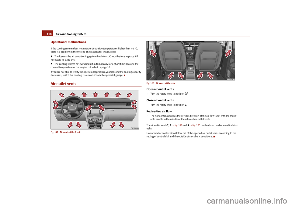
Air outlet ventsFig. 119 Air vents at the front Fig. 120 Air vents at the rear
Open air outlet vents– Turn the rotary knob to position
.
Close air outlet vents– Turn the rotary knob to position
0.Redirecting air flow– The horizontal as well as the vertical dire ction of the air flow is set with the move-
able handle in the middle of the relevant air outlet vents.
The air outlet vents 2, 3 fig. 119 and 5 fig. 120 can be closed and opened individ-
ually.
Unwarmed or cooled air will flow out of the opened air outlet vents according to the
setting of control dial and the outside atmospheric conditions.
s3fg.2.book Page 110 Friday, April 30, 2010 12:17 PM
Page 115 of 287
Air conditioning system
114
Climatronic* (automatic air conditioning)Description
The Climatronic system is a combination of an automatic heating, fresh
air and cooling system which provides optimal comfort for the occu-
pants of the car.The Climatronic maintains fu lly automatically a convenience temperature. This is
achieved by automatically varying the temper ature of the outflowing air, the blower
stages and the air distribution. The system also takes into account sunlight which elim-
inates the need to alter the settings manually. The automatic mode page 115
ensures maximum wellbeing of the occupants at all times of the year.
Description of Climatronic system
The cooling operates only if the following conditions are met:
engine running,
outside temperature above approx. +2°C,
switched on.
The AC compressor is switched off at a hi gh coolant temperature in order to provide
cooling at a high load of the engine.
Recommended setting for all periods of the year:
Set the desired temperature, we recommend 22°C.
Press the button fig. 122 .
Move the air outlet vents 2 and 3 so that the air flow is directed slightly upwards.
Aeration of the vehicle when ignition is switched off*
On vehicles fitted with power sliding/tilting roof with solar cells* the fresh air blower is
automatically switched over to “solar mo de” if the sun rays are sufficient after
switching off the ignition. The solar cells on the sliding/tilting roof deliver power for the
fresh air blower. This supplies the interior of the car with fresh air.
For an optimum ventilation, the air outlet vents 2 and 3 page 110, fig. 119 must be
opened.
The ventilation functions only when the sliding/tilting roof is closed.
Note
On vehicles equipped with a factory-fitted radio* or navigation*, the information of
the Climatronic is also shown on the display. This function can be switched off, see
operating instructions of the radio* or the navigation system*.Overview of the control elements
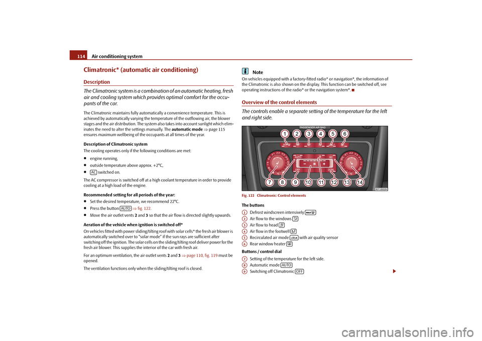
The controls enable a separate setting of the temperature for the left
and right side.Fig. 122 Climatronic: Control elementsThe buttons
Defrost windscreen intensively
Air flow to the windows
Air flow to head
Air flow in the footwell
Recirculated air mode with air quality sensor
Rear window heater
Buttons / control dial Setting of the temperature for the left side.
Automatic mode
Switching off Climatronic
AC
AUTO
A1
A2
A3
A4
A5
A6
A7A8
AUTO
A9
OFF
s3fg.2.book Page 114 Friday, April 30, 2010 12:17 PM
Page 118 of 287
Air conditioning system117
Using the system
Safety
Driving Tips
General Maintenance
Breakdown assistance
Technical Data
Defrosting windscreenDefrosting windscreen - switching on– Press the button page 114, fig. 122.Defrosting windscreen - switching off– Once again press the button or the button .
The temperature control is controlled automatically. More air flows out of the air outlet
vents 1.Auxiliary heating (auxiliary heating and ventilation)*Description and important information
The auxiliary heating (auxiliary heating and ventilation) heats or
supplies the interior of the vehicl e with fresh air independent of the
engine.Auxiliary heating (auxiliary heating)
The auxiliary heating (auxiliary heating) functions in connection with the Climatic or
Climatronic.
It can be used when stationary, when engi ne is switched off for preheating of the
vehicle as well as while driving (e.g. during the heating phase of the engine).
The engine is also preheated when the vehicle is stationary and the engine is switched
off, if the auxiliary heating is switched on. This is not valid for the engines 3.6 ltr./191 kW
FSI and 1.9 ltr./77 kW TDI.
The auxiliary heating (auxiliary heating) wa rms up the coolant during the combustion
of fuel from the vehicle tank. The coolant warms up the air, which (if the blower speed
is not set to zero) flows in to the occupant compartment.
Auxiliary ve ntilation
The auxiliary ventilation enables fresh air to flow into the vehicle interior by switching
off the engine, whereby the interior temperature is effectively decreased (e.g. with the
vehicle parked in the sun).
WARNING
The auxiliary heating must never be operated in closed rooms - risk of
poisoning!
The auxiliary heating must not be running during refueling - risk of fire.
The exhaust pipe of the auxiliary heatin g is located on the underside of the
vehicle. Therefore do not place the vehicle, if you wish to operate the auxiliary
heating, in such a way that the exhaust gases of the auxiliary heating can come
easily into contact with inflammable mate rials (e.g. dry grass) or easily inflam-
mable substances (e .g. fuel run out).Note
If the auxiliary heating runs, the fuel consumption comes from the vehicle tank.
Therefore the auxiliary heating should not be operated, if there is very little fuel in the
tank.
The exhaust pipe of the auxiliary heating, which is located on the underside of the
vehicle, must not be clogged and th e exhaust flow must not be blocked.
If the auxiliary heating and ventilation is running, the vehicle battery discharges. If
the auxiliary heating and ventilation has been operated several times over a longer
period, the vehicle must be driven a few ki lometers in order to recharge the vehicle
battery.
The auxiliary heating only switches the bl ower on, if it has achieved a coolant
temperature of approx. 50 °C.
At low outside temperatures, this can result in a formation of water vapour in the
area of the engine compartment. This is qu ite normal and is not an operating problem.
After switching off the auxiliary heating, the coolant pump runs for a short period.
The auxiliary heating and ventilation does not switch on or comes on, if the vehicle
battery indicates a low loading state.
The auxiliary heating (auxiliary heating) does not switch on, if the following was
shown in the information display or before switching off the ignition: Please refuel!
The air inlet in front of the windscreen must be free of ice, snow or leaves in order
to ensure that the auxiliary heating operates properly.
AUTO
s3fg.2.book Page 117 Friday, April 30, 2010 12:17 PM
Page 119 of 287
Air conditioning system
118
So that warm air can flow into the vehicl e interior after switching on the auxiliary
heating, you must maintain the temperat ure normally selected by you (we recom-
mend 22°C). It is recommended to put the air flow in the position
.
On vehicles with DPF (diesel particle filter) the warm coolant heats up the engine.
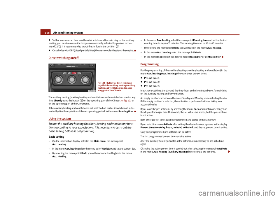
Direct switching on/offThe auxiliary heating (auxiliary heating and vent ilation) can be switched on or off at any
time directly using the button on the operating part of the Climatic fig. 123 or
on the operating part of the Climatronic.
If the auxiliary heating and ventilation is not switched off earlier, it switches off auto-
matically after the expiration of the set operating period, in the menu Running time.Using the system
So that the auxiliary heating (auxiliary heating and ventilation) func-
tions according to your expectations, it is necessary to carry out the
basic setting before its programming.Basic setting– On the information display, select in the Main menu the menu point
Aux. heating .
– In the menu Aux. heating select the menu point Weekday and set the current day.
– By selecting the menu point Back, you will reach one level higher in the menu
Aux. Heating . – In the menu
Aux. heating select the menu point Running time and set the desired
running time in steps of 5 minutes. The running time can be 10 to 60 minutes.
– By selecting the menu point Back, you will reach in the menu Aux. heating.
– In the menu Aux. heating select the menu point Mode.
– In the menu Mode select the desired mode Heating for or Ventilation for .
ProgrammingFor the programming of the auxiliary heating (auxiliary heating and ventilation) in the
menu Aux. heating (Aux. heating) there are three pre-set times:
Pre-set time 1
Pre-set time 2
Pre-set time 3
In each pre-set time, the day and the time (hour and minute) can be set for switching
on the auxiliary heating and/or ventilation.
An empty position can be found between S unday and Monday when selecting the day.
If this empty position is selected, the activation is performed without taking into
account the day.
If you leave the pre-set menu by selecting the menu Back or do not make changes on
the display for longer than 10 seconds, the set values are stored, but the pre-set time
is not active.
Both other pre-set times can be prog rammed and stored in the same way.
If you select the menu Activate after setting the desired values, appears in the display
Pre-set time (weekday, hours, minute) activated. and the set pre-set time is active.
Only one programmed pre-set time can be active.
The last programmed pre-set time remains active.
After the auxiliary heating activates at the set time, it is necessary to pre-set a time
again.
Changing the active pre-set time is carried out after selecting the menu point Activate
in the menu Aux. heating (auxiliary heating) by selecting a pre-set time.
Fig. 123 Button for direct switching
on/off of the auxiliary heating (auxiliary
heating and ventilation) on the oper-
ating part of the Climatic
s3fg.2.book Page 118 Friday, April 30, 2010 12:17 PM