clock SKODA SUPERB 2010 2.G / (B6/3T) Technical Change
[x] Cancel search | Manufacturer: SKODA, Model Year: 2010, Model line: SUPERB, Model: SKODA SUPERB 2010 2.G / (B6/3T)Pages: 18, PDF Size: 0.76 MB
Page 8 of 18

Tyre repair kit*7
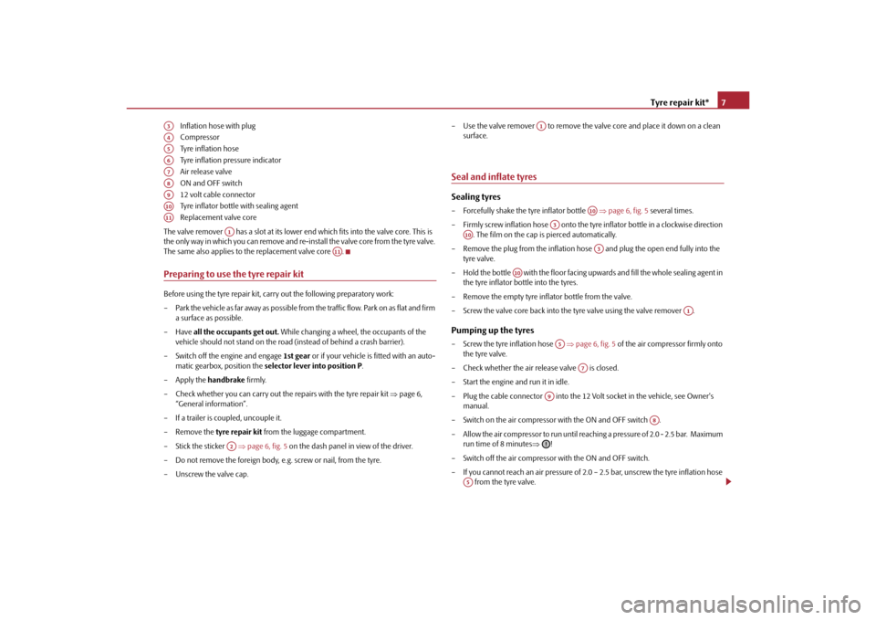
Inflation hose with plug
Compressor
Tyre inflation hose
Tyre inflation pressure indicator
Air release valve
ON and OFF switch
12 volt cable connector
Tyre inflator bottle with sealing agent
Replacement valve core
The valve remover has a slot at its lower end which fits into the valve core. This is
the only way in which you can remove and re-i nstall the valve core from the tyre valve.
The same also applies to the replacement valve core .
Preparing to use the tyre repair kitBefore using the tyre repair kit, carry out the following preparatory work:
– Park the vehicle as far away as possible from the traffic flow. Park on as flat and firm
a surface as possible.
–Have all the occupants get out. While changing a wheel, the occupants of the
vehicle should not stand on the road (instead of behind a crash barrier).
– Switch off the engine and engage 1st gear or if your vehicle is fitted with an auto-
matic gearbox, position the selector lever into position P .
– Apply the handbrake firmly.
– Check whether you can carry out the repairs with the tyre repair kit page 6,
“General information”.
– If a trailer is coupled, uncouple it.
– Remove the tyre repair kit from the luggage compartment.
– Stick the sticker page 6, fig. 5 on the dash panel in view of the driver.
– Do not remove the foreign body, e.g. screw or nail, from the tyre.
– Unscrew the valve cap. – Use the valve remover to remove the valve core and place it down on a clean
surface.
Seal and inflate tyresSealing tyres– Forcefully shake the tyre inflator bottle page 6, fig. 5 several times.
– Firmly screw inflation hose onto the tyre inflator bottle in a clockwise direction . The film on the cap is pierced automatically.
– Remove the plug from the inflation hose and plug the open end fully into the tyre valve.
– Hold the bottle with the floor facing upwards and fill the whole sealing agent in the tyre inflator bottle into the tyres.
– Remove the empty tyre inflator bottle from the valve.
– Screw the valve core back into the tyre valve using the valve remover .Pumping up the tyres– Screw the tyre inflation hose page 6, fig. 5 of the air compressor firmly onto
the tyre valve.
– Check whether the air re lease valve is closed.
– Start the engine and run it in idle.
– Plug the cable connector into the 12 Vo lt socket in the vehicle, see Owner's
manual.
– Switch on the air compressor with the ON and OFF switch .
– Allow the air compressor to run until reachi ng a pressure of 2.0 - 2.5 bar. Maximum
run time of 8 minutes !
– Switch off the air compressor with the ON and OFF switch.
– If you cannot reach an air pressure of 2.0 – 2.5 bar, unscrew the tyre inflation hose from the tyre valve.
A3A4A5A6A7A8A9A10A11
A1
A11
A2
A1
A10
A3
A10
A3
A10
A1
A5
A7
A9
A8
A5
s3lg.1.book Page 7 Monday, September 20, 2010 8:07 AM
Page 10 of 18

Technical Data9
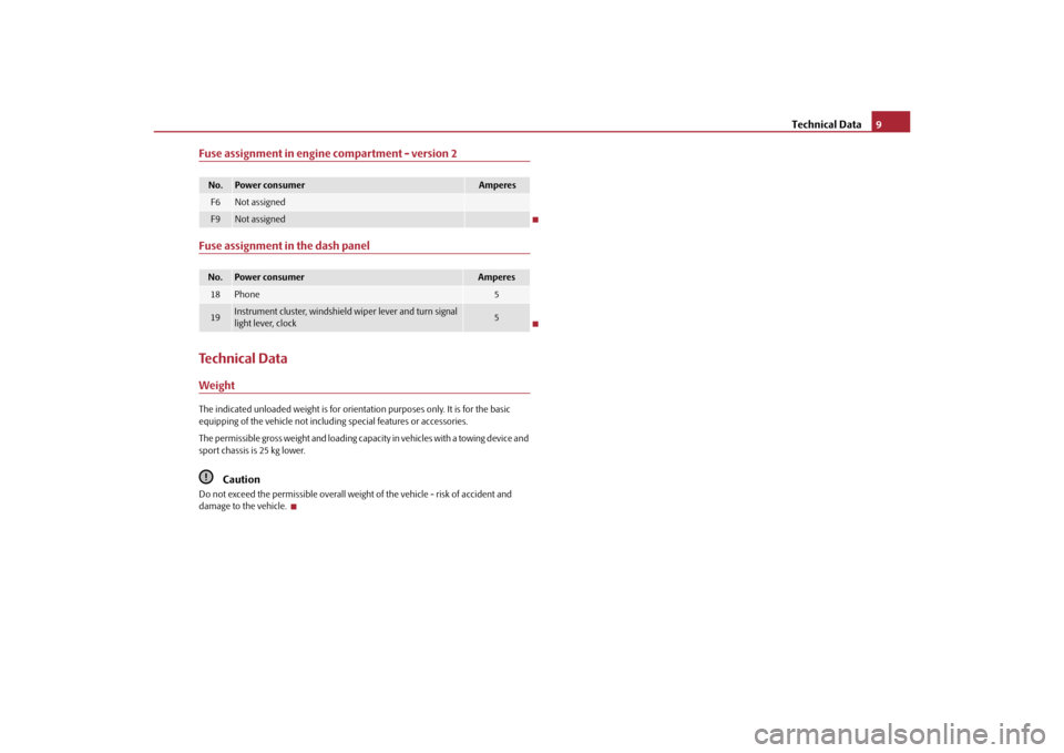
Fuse assignment in engine compartment - version 2Fuse assignment in the dash panelTechnical DataWeightThe indicated unloaded weight is for orient ation purposes only. It is for the basic
equipping of the vehicle not includin g special features or accessories.
The permissible gross weight and loading capaci t y i n v e h i c l e s w i th a to w i n g d e v i c e a n d
sport chassis is 25 kg lower.
Caution
Do not exceed the permissibl e overall weight of the vehicle - risk of accident and
damage to the vehicle. No.
Power consumer
Amperes
F6
Not assigned
F9
Not assigned
No.
Power consumer
Amperes
18
Phone
5
19
Instrument cluster, windshield wiper lever and turn signal
light lever, clock
5
s3lg.1.book Page 9 Monday, September 20, 2010 8:07 AM