heater SKODA SUPERB 2010 Owner´s Manual
[x] Cancel search | Manufacturer: SKODA, Model Year: 2010, Model line: SUPERB, Model: SKODA SUPERB 2010Pages: 252, PDF Size: 16.33 MB
Page 123 of 252
■Starting time 1 , Starting time 2 , Starting time 3 - for each pre-set time, the
day and the time (hour and minute) can be set for switching on the auxiliary
heating. An empty position can be found between Sunday and Monday when
selecting the day. If this empty position is selected, the activation is per-
formed without taking into account the day.
■ Activate - Activate pre-set mode;
■ Deactivate - Deactivate pre-set mode;
■ Factory settings - Restore factory settings
■ Back - Return to main menu
Only one programmed pre-set time can be active.
The last programmed pre-set time remains active.
After the auxiliary heating activates automatically at the set time, it is neces-
sary to pre-set a time again.
If the menu item Back is selected or no changes are made on the display for
longer than 10 seconds, the set values are stored, but the pre-set time is not
activated.
The system switches itself off at the end of the running time set under the
menu item Running time .
Note
A warning light on the button » Fig. 127 illuminates when the system is run-
ning.
Radio remote control
Fig. 128
Auxiliary heater: Radio remote
control
Read and observe and on page 119 first.
Explanation of graphic » Fig. 128
Aerial
Warning light
Switch on the auxiliary heating
Switch off the auxiliary heating
The transmitter and the battery are housed in the housing of the remote con- trol. The receiver is located in the interior of the vehicle.
When the battery is fully charged, the range of the remote control is a few
hundred metres. Obstacles between the remote control and the vehicle, bad
weather conditions and a weaker battery in the remote control can clearly re-
duce the range.
To switch the auxiliary heating on or off, hold the remote control vertically,
with the aerial
A
pointing upwards. The antenna must not be covered with
the fingers or the palm of the hand during this process.
The auxiliary heating can only be switched on/off safely using the radio re-
mote control, if the distance between the radio remote control and the vehicle
is at least 2 m.
After pressing the button, the warning light in the remote control gives the
user different kinds of feedback:
Display warning light B » Fig. 128MeaningLights up green for around 2 seconds.The auxiliary heating has been
switched on.Lights up red for around 2 seconds.The auxiliary heating has been
switched off.Slowly flashes green for around 2 sec-
onds.The ignition signal was not received.Quickly flashes green for around 2
seconds.The auxiliary heating is blocked, e. g
because the tank is nearly empty or
there is a fault in the auxiliary heat-
ing.Flashes red for around 2 seconds.The switch off signal was not re-
ceived.Lights up orange for around 2 sec-
onds, then green or red.The battery is weak, however the
switching on or off signal was re-
ceived. AB120Operation
Page 185 of 252
■Sharp-edged objects on items of clothing such as zip fasteners, rivets, sharp-
edged belts, jewellery and pendants may leave permanent scratches or signs
of rubbing on the surface. Such damage cannot be subsequently recognised as
a justified complaint.■
The use of an additional mechanical steering wheel lock may damage the
leather surface of the steering wheel.
■
Use a care cream with light blocker and impregnation effect on a regular ba-
sis and each time after cleaning. The cream nourishes the leather, allows it to
breathe and keeps it supple and also provides moisture. It also creates surface
protection.
■
Some clothing materials, e.g. dark denim, do not have sufficient colour fast-
ness. This can cause damage or clearly visible discolouration to seat covers,
even when used correctly. This applies particularly to light-coloured seat cov-
ers. This does not relate to a fault in the seat cover, but rather to poor colour
fastness of the clothing textiles.
Note
When using the vehicle, minor visible changes may occur to the leather parts
of the covers (e.g. wrinkles or creases) as a result of the stress applied to the
covers.
Synthetic leather, fabrics and Alcantara ®
Read and observe
and on page 181 first.
Artificial leather
Clean artificial leather with a damp cloth.
If this method does not completely clean the artificial leather, use a mild soap
solution or cleaning products specially designed for this purpose.
Fabric
Clean upholstery cover materials and cloth trims on doors, boot cover, etc. us-
ing specific cleaning agents, e.g., dry foam.
Use a soft sponge, brush, or commercially available microfibre cloth.
Use a cloth and special detergent to clean the headlining.
Remove any lumps on the cover fabric and any fabric residue using a brush.
Remove stubborn hair using a “cleaning glove”.
Alcantara ®
Dust and fine dirt particles in pores, creases and seams may chafe and damage
the surface.
If you leave your vehicle parked in the open for lengthy periods, protect the Al-
cantara ®
seat upholstery from direct sunlight to prevent fading.
Minor changes in colour caused by use are normal.
CAUTION
■ Do not use leather cleaners on Alcantara ®
seat upholstery.■Do not use solvents, floor wax, shoe cream, stain remover or similar agents
on Alcantara ®
seat upholstery.■
Avoid leaving the vehicle in bright sunlight for long periods of time in order
to stop the fabric from bleaching. If the vehicle is parked outside for long peri-
ods of time, cover the fabric to protect it from direct sunlight.
■
Some clothing materials, e.g. dark denim, do not have sufficient colour fast-
ness. This can cause damage or clearly visible discolouration to seat covers,
even when used correctly. This applies particularly to light-coloured seat cov-
ers. This does not relate to a fault in the seat cover, but rather to poor colour
fastness of the clothing textiles.
Seat covers
Read and observe
and on page 181 first.
Electrically heated seats
Do not clean the covers by moistening, as this can damage the seat heating
system.
Use a specific cleaning agent such as dry foam or similar to clean the covers.
Seats without seat heating
Thoroughly vacuum the seat covers with a vacuum cleaner before cleaning.
Clean the seat covers with a damp cloth or cleaning products specially de-
signed for this purpose.
Indented points arising on the fabrics by everyday use, can be removed by
brushing against the direction of hair with a damp brush.
Always clean all parts of the covers, so that there are no visible edges. Then
allow the seat to dry completely.
CAUTION
■ Regularly remove dust from the seat covers using a vacuum cleaner.■Electrically heated seats must not be dried after cleaning by switching on the
heater. 182General Maintenance
Page 194 of 252
ReplenishingRead and observe
and on page 189 first.
›
Check the oil level » page 190.
›
Unscrew the cap of the engine oil filler opening » Fig. 164 on page 188 .
›
Replenish the oil in portions of 0.5 litres in accordance with the correct speci-
fications » page 189 .
›
Check the oil level » page 190.
›
Carefully screw on the oil filler opening cap and push the dipstick in fully.
Coolant
Introduction
This chapter contains information on the following subjects:
Capacity
191
Checking the coolant level
192
Replenishing
192
The coolant consists of water with coolant additive. This mixture guarantees
antifreeze protection, protects the cooling/heater system against corrosion
and prevents lime formation.
Vehicles exported to countries with a mild climate are already factory-filled
with a coolant which offers antifreeze protection down to about -25 ℃. In
these countries, the concentration of coolant additive should be at least 40%.
Vehicles exported to countries with a cold climate are already factory-filled
with a coolant which offers antifreeze protection down to about -35 °C. In
these countries, the concentration of coolant additive should be at least 50%.
If a higher concentration of antifreeze is required for climatic reasons, the con-
centration of coolant additive can be increased up to a maximum of 60% (anti-
freeze protection down to approx. -40 °C).
When refilling, only use the same antifreeze identified on the coolant expan-
sion vessel » Fig. 167 on page 192 .
WARNINGThe engine compartment of your car is a hazardous area. The following
warning instructions must be followed at all times when working in the en- gine compartment » page 186.
CAUTION
■
Do not continue if for some reason it is not possible to fill with coolant un-
der the current circumstances! Switch off the engine and seek assistance from
a specialist garage.■
If the expansion tank is empty, do not top up with coolant. The system could
ventilate - there is a risk of engine damage,
do not continue driving! Switch
off the engine and seek assistance from a specialist garage.
■
The concentration of coolant additive in the coolant must never be under
40%.
■
Over 60% of coolant additive in the coolant reduces the antifreeze protec-
tion and cooling effect.
■
A coolant additive that does not comply with the correct specifications can
significantly reduce the corrosion protection.
■
Any faults resulting from corrosion may cause a loss of coolant and can con-
sequently result in major engine damage!
■
Do not fill the coolant above the mark
A
» Fig. 167 on page 192 .
■
If a fault causes the engine to overheat, we recommend visiting a specialist
garage, as otherwise serious engine damage may occur.
■
Additional headlights and other attached components in front of the air inlet
impair the cooling efficiency of the coolant.
■
Never cover the radiator - there is a risk of the engine overheating.
Capacity
Read and observe
and on page 191 first.
Coolant capacity (in litres) 1)
Petrol enginesCapacity1.4 l/92 kW TSI7.71.8 l/112 kW TSI
1.8 l/118 kW TSI8.6 1)
The coolant capacity is approximately 1 Litre greater on vehicles that are fitted with an auxiliary heater
(auxiliary heating and ventilation).
191Inspecting and replenishing
Page 200 of 252

NoteWe recommend having the vehicle checked by a specialist garage in order to
ensure full functionality of all electrical systems.
Automatic load deactivation
Read and observe
and on page 194 first.
The vehicle voltage control unit automatically prevents the battery from dis-
charging when the battery is put under high levels of strain. This may be no-
ticed from the following.
› The idling speed is raised to allow the generator to deliver more electricity to
the electrical system.
› Where necessary, large convenience consumers such as seat heaters and
rear window heaters have their power limited or are shut off completely in
the event of an emergency.
CAUTION
■ Despite such intervention by the vehicle electric system management, the
vehicle battery may be drained. For example, when the ignition is switched on
a long time with the engine turned off or the side or parking lights are turned
on during longer parking.■
Consumers that are supplied via a 12-V power socket can cause the vehicle
battery to discharge when the ignition is switched off.
Note
Driving comfort is not impaired by consumers being deactivated. The driver is
often not aware of it having taken place.Wheels
Tyres and wheel rims
Introduction
This chapter contains information on the following subjects:
Service life of tyres
198
Unidirectional tyres
199
Spare and temporary spare wheel
200
Full wheel trim
200
Wheel bolts
201
Only use tyres or wheel rims that have been approved by ŠKODA for your mod-
el of vehicle.
WARNINGThe national legal regulations must be observed for the use of tyres.WARNINGInstructions for the use of tyres■For the first 500 km, new tyres do not yet provide optimum grip, and ap-
propriate care should therefore be taken when driving – risk of accident!■
For reasons of driving safety, do not replace tyres individually.
■
Never exceed the maximum permissible load bearing capacity of moun-
ted tyres.
■
Never exceed the maximum permissible speed for the mounted tyres.
■
An incorrect wheel alignment at the front or rear impairs handling.
■
Unusual vibrations or pulling of the vehicle to one side could be a sign of
tyre damage. If there is any doubt that a wheel is damaged, immediately re-
duce your speed and stop! If no external damage is evident, drive slowly
and carefully to the nearest specialist garage to have the vehicle checked.
WARNINGInformation regarding tyre damage or wear■Never use tyres if you do not know anything about the condition and age.■
Never drive with damaged tyres – there is the risk of an accident occur-
ring.
197Wheels
Page 218 of 252
If the towing device is removed completely, it must be replaced with the
standard reinforcement of the rear bumper which is part of the mount for the
towing eye.
If this procedure is not observed, the vehicle may not meet the national legal
provisions.
CAUTION
The detachable ball rod and/or the vehicle can be damaged if an unsuitable
tow bar is used.
Note
The detachable ball rod must always be in the vehicle so that it can be used for
towing, if necessary.
Radio remote control
Introduction
This chapter contains information on the following subjects:
Replacing the battery in the remote control key
215
Synchronising the remote control
215
Replace the battery in the remote control of the auxiliary heater (parking
heater)
216
CAUTION
■ The replacement battery must have the same specification as the original
battery.■
We recommend having faulty batteries replaced by a ŠKODA service partner.
■
Pay attention to the correct polarity when changing the battery.
For the sake of the environment
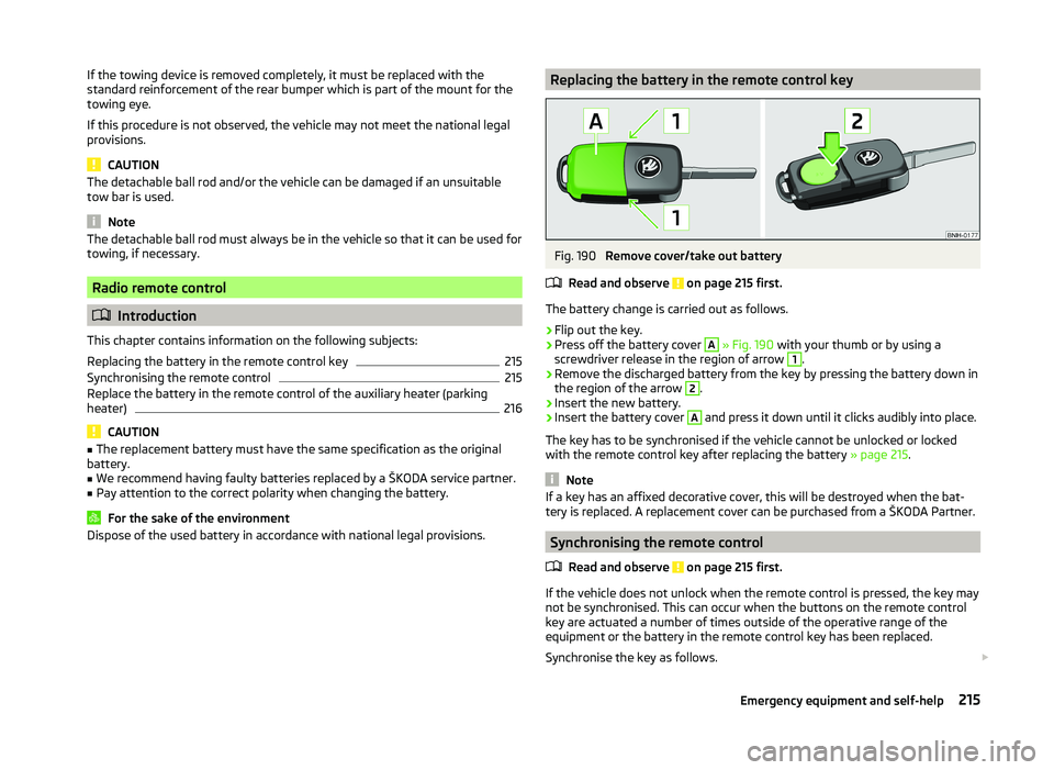
Dispose of the used battery in accordance with national legal provisions.Replacing the battery in the remote control keyFig. 190
Remove cover/take out battery
Read and observe
on page 215 first.
The battery change is carried out as follows.
›
Flip out the key.
›
Press off the battery cover
A
» Fig. 190 with your thumb or by using a
screwdriver release in the region of arrow
1
.
›
Remove the discharged battery from the key by pressing the battery down in
the region of the arrow
2
.
›
Insert the new battery.
›
Insert the battery cover
A
and press it down until it clicks audibly into place.
The key has to be synchronised if the vehicle cannot be unlocked or locked
with the remote control key after replacing the battery » page 215.
Note
If a key has an affixed decorative cover, this will be destroyed when the bat-
tery is replaced. A replacement cover can be purchased from a ŠKODA Partner.
Synchronising the remote control
Read and observe
on page 215 first.
If the vehicle does not unlock when the remote control is pressed, the key maynot be synchronised. This can occur when the buttons on the remote control
key are actuated a number of times outside of the operative range of the
equipment or the battery in the remote control key has been replaced.
Synchronise the key as follows.
215Emergency equipment and self-help
Page 219 of 252

›Press any button on the remote control key.›Unlock the door with the key in the lock cylinder within 1 minute of pressing
the button.
Replace the battery in the remote control of the auxiliary heater
(parking heater)
Fig. 191
Radio remote control: Battery
cover
Read and observe on page 215 first.
The battery is located under a cover on the back of the radio remote con-
trol » Fig. 191 .
›
Insert a flat, blunt object, such as a coin, into the gap of the battery cover.
›
Turn the cover against the direction of the arrow up to the mark to open the
cover.
›
Replace the battery.
›
Return the battery cover.
›
Turn the cover in the direction of the arrow up to the initial marking, engage.
Emergency unlocking/locking
Introduction
This chapter contains information on the following subjects:
Unlocking/locking the driver's door
216
Locking the door without a locking cylinder
217
Unlocking the boot lid
217
Selector lever-emergency unlocking
217Unlocking/locking the driver's doorFig. 192
Handle on the driver's door: cov-
ered key cylinder
The driver's door can be unlocked or locked in an emergency.
›
Pull on the door handle and hold it pulled.
›
Insert the vehicle key into the slot on the underside of the cover in the re-
gion of the arrow » Fig. 192.
›
Fold the cover upwards.
›
Release the door handle.
›
Insert the remote control key into the lock cylinder and unlock or lock the ve-
hicle.
›
For vehicles with LHD insert the remote control key with the buttons facing
up into the lock cylinder and unlock or lock the vehicle.
›
For vehicles with RHD insert the remote control key directed with buttons
down into the lock cylinder and unlock or lock the vehicle.
Pull on the door handle and install the cover to the original location.
CAUTION
Make sure you do not damage the paint when performing an emergency lock-
ing/unlocking.216Do-it-yourself
Page 224 of 252
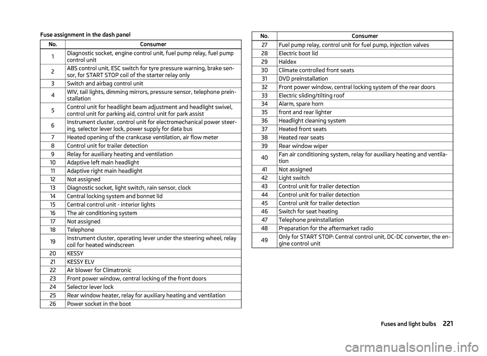
Fuse assignment in the dash panelNo.Consumer1Diagnostic socket, engine control unit, fuel pump relay, fuel pump
control unit2ABS control unit, ESC switch for tyre pressure warning, brake sen-
sor, for START STOP coil of the starter relay only3Switch and airbag control unit4WIV, tail lights, dimming mirrors, pressure sensor, telephone prein-
stallation5Control unit for headlight beam adjustment and headlight swivel,
control unit for parking aid, control unit for park assist6Instrument cluster, control unit for electromechanical power steer-
ing, selector lever lock, power supply for data bus7Heated opening of the crankcase ventilation, air flow meter8Control unit for trailer detection9Relay for auxiliary heating and ventilation10Adaptive left main headlight11Adaptive right main headlight12Not assigned13Diagnostic socket, light switch, rain sensor, clock14Central locking system and bonnet lid15Central control unit - interior lights16The air conditioning system17Not assigned18Telephone19Instrument cluster, operating lever under the steering wheel, relay
coil for heated windscreen20KESSY21KESSY ELV22Air blower for Climatronic23Front power window, central locking of the front doors24Selector lever lock25Rear window heater, relay for auxiliary heating and ventilation26Power socket in the bootNo.Consumer27Fuel pump relay, control unit for fuel pump, injection valves28Electric boot lid29Haldex30Climate controlled front seats31DVD preinstallation32Front power window, central locking system of the rear doors33Electric sliding/tilting roof34Alarm, spare horn35front and rear lighter36Headlight cleaning system37Heated front seats38Heated rear seats39Rear window wiper40Fan air conditioning system, relay for auxiliary heating and ventila-
tion41Not assigned42Light switch43Control unit for trailer detection44Control unit for trailer detection45Control unit for trailer detection46Switch for seat heating47Telephone preinstallation48Preparation for the aftermarket radio49Only for START STOP: Central control unit, DC-DC converter, the en-
gine control unit221Fuses and light bulbs
Page 226 of 252
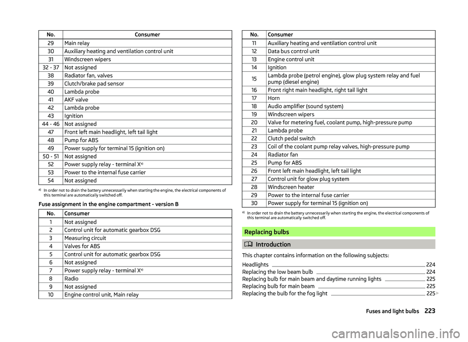
No.Consumer29Main relay30Auxiliary heating and ventilation control unit31Windscreen wipers32 - 37Not assigned38Radiator fan, valves39Clutch/brake pad sensor40Lambda probe41AKF valve42Lambda probe43Ignition44 - 46Not assigned47Front left main headlight, left tail light48Pump for ABS49Power supply for terminal 15 (ignition on)50 - 51Not assigned52Power supply relay - terminal Xa)53Power to the internal fuse carrier54Not assigneda)
In order not to drain the battery unnecessarily when starting the engine, the electrical components of
this terminal are automatically switched off.
Fuse assignment in the engine compartment - version B
No.Consumer1Not assigned2Control unit for automatic gearbox DSG3Measuring circuit4Valves for ABS5Control unit for automatic gearbox DSG6Not assigned7Power supply relay - terminal X a)8Radio9Not assigned10Engine control unit, Main relayNo.Consumer11Auxiliary heating and ventilation control unit12Data bus control unit13Engine control unit14Ignition15Lambda probe (petrol engine), glow plug system relay and fuel
pump (diesel engine)16Front right main headlight, right tail light17Horn18Audio amplifier (sound system)19Windscreen wipers20Valve for metering fuel, coolant pump, high-pressure pump21Lambda probe22Clutch pedal switch23Coil of the coolant pump relay valves, high-pressure pump24Radiator fan25Pump for ABS26Front left main headlight, left tail light27Control unit for glow plug system28Windscreen heater29Power to the internal fuse carrier30Power supply for terminal 15 (ignition on)a)
In order not to drain the battery unnecessarily when starting the engine, the electrical components of
this terminal are automatically switched off.
Replacing bulbs
Introduction
This chapter contains information on the following subjects:
Headlights
224
Replacing the low beam bulb
224
Replacing bulb for main beam and daytime running lights
225
Replacing bulb for main beam
225
Replacing the bulb for the fog light
225
223Fuses and light bulbs
Page 239 of 252
Index
A
Abroad Driving abroad
153
Unleaded petrol153
ABS Operation
155
Warning light38
Accessories173
Adaptive headlights (AHL)70
Adjust Auxiliary heating (auxiliary heating and ventila- tion)
119
Head restraints83
Adjusting Belt height
15
Exterior mirrors80
Interior mirror79
Manual air conditioning114
Seats81, 82
Steering wheel10
Adjusting the seats9, 81
Adjustment Range of light
68
Aerial177
See windows179
AHL70
Warning light38
Airbag16
Deactivating21
Deactivating the front passenger airbag21
Deployment16
Front airbag17
Head airbag20
Indicator light40
Knee airbag18
Modifications and damage to the airbag system 175
Side airbag
19
Airbag system16
Air conditioning system110
Air outlets110
Climatronic115
Manual air conditioning system112
Air outlets110
Air recirculation Climatronic
117
Alarm Switching off
55
Triggering55
Anti-theft alarm system Activating/deactivating
56
Trailer172
Anti-theft wheel bolts208
Antilock brake system (ABS)155
Armrest Front
87
rear96
Rear87
Ashtray91
ASR Operation
155
warning light37
Assist systems154
ABS38, 155
ASR37, 155
Cruise Control System161
DSR155
EDL155
ESC37, 154
HBA155
HHC156
Park assist157
Parking aid156
START STOP162
Audio see radio / navigation system
4
Auto Check Control33
Automatic driving lamp control70
Automatic gearbox Selector lever-emergency unlocking217
Starting off and driving147
Tiptronic146
Using the selector lever145
Automatic gearbox modes145
Automatic load deactivation197
Automatic retractable cargo cover (Superb Combi))
101
Automatic transmission145
Kickdown147
Malfunction148
Selector lever lock146
AUX Installation in the storage compartment
92
Auxiliary heating (auxiliary heating and ventila- tion)
118
Adjust119
Radio remote control120
Switching on/off119
Avoiding damage to the vehicle Driving through water
152
Avoiding damage to your vehicle152
B
Ball head Check fitting
168
Fitting168
Ready position167
Removing169
Battery In the remote control key
215
Replace the remote control of the auxiliary heater (parking heater)
216
Belts12
Belt tensioners15
Bonnet Closing
187
Opening187
Warning light36
236Index
Page 243 of 252
HBA155
Head airbag20
Headlight cleaning system Headlight cleaning system
79
Headlights Driving abroad
153
Headlight cleaning system79
Replacing a bulb224
Head restraint83
Head restraints83
Heater Windscreen and rear window
75
Heating Exterior mirrors
80
Seats85
HHC156
Hill Hold Control (HHC)156
Hitch166
Accessories169
Drawback load166
Horn29
Hydraulic Brake Assist (HBA)155
I
Ignition
139
Immobilizer139
Individual settings Locking
54
Unlocking54
Inertia reels15
Information messages see KESSY
53
Information system42
Compass point display48
Display a low temperature43
Door warning44
Gear recommendation43
MAXI DOT display46
Multifunction display44
Operation42
Service interval display48
instrument cluster Auto Check Control
33
Instrument cluster30
Counter for distance driven32
Display31
Display of the second speed33
Fuel gauge32
Overview30
Revolution counter31
see instrument cluster30
Speedometer31
Temperature gauge31
Warning lights34
Interior monitor56
Internet connection129
ISOFIX25
J
Jack
205
Maintenance180
Jacking points Raise vehicle
207
Jump-starting211
K
KESSY Information messages
53
Lock / unlock the steering141
Locking53
Starting the engine142
Switching off the engine142
Switch off ignition141
Switch on ignition141
Unlocking53
Key Starting the engine
139
Stopping the engine140
Knee airbag18
L
Lamp failure Warning light
38
Lamps Warning light
38
LEAVING HOME72
Lever Main beam
69
Turn signal69
Windscreen wipers78
Light Cockpit
73
COMING HOME / LEAVING HOME72
Fog lights with CORNER function71
Headlight range control68
Instrument illumination68
Low beam68
Parking light68
switching on and off68
Travel mode71
Light bulbs Rear light (Superb Combi)
226
Lighting Luggage compartment
97
Lights67
Adaptive headlights (AFS)70
Automatic driving lamp control70
Daylight running69
Fog lights71
Hazard warning light system72
Headlight flasher69
Main beam69
Parking lights73
Rear fog light71
Replacing bulbs223
Tourist lights71
Turn signal69
Warning lights34
Lock Vehicle key
51
240Index