battery SKODA SUPERB 2010 Owner´s Manual
[x] Cancel search | Manufacturer: SKODA, Model Year: 2010, Model line: SUPERB, Model: SKODA SUPERB 2010Pages: 252, PDF Size: 16.33 MB
Page 89 of 252
If the engine is switched off and then turned on again within 10 mins with the
rear seat heating switched, then each rear seat heating is automatically turned
on again.WARNINGIf you have a subdued pain and/or temperature sensitivity, e.g. through
medication, paralysis or because of chronic illness (e.g. diabetes), we rec-
ommend not to use the seat heating. This can lead to burns on the back,
the posterior and the legs which are difficult to heal. If the seat heating is
used, we recommend to make regular breaks in your journey when driving
long distances, so that the body can recuperate from the stress of the jour-
ney. Please consult your doctor, who can evaluate your specific condition.
CAUTION
■ Do not kneel on the seats or otherwise apply concentrated pressure to them.■The seat heater in the following cases will not turn on - there is a risk of
damaging the seat covers and seat heater. ■The seats are not occupied.
■ Items are fastened to or stored on the seats e.g. child seat, bags etc.
■ Additional seat covers or protective covers are fixed to the seats.■
Clean the seat covers » page 182, Seat covers .
Note
■
If the rear seat heating is set to the highest intensity - level 3, it is automati-
cally switched over to level 2 after 10 minutes (two warning lights are illumina-
ted on the switch).■
If the on-board voltage drops, the heater switches off automatically in order
to provide sufficient electrical power for the engine control » page 197.
Ventilated front seats
Fig. 73
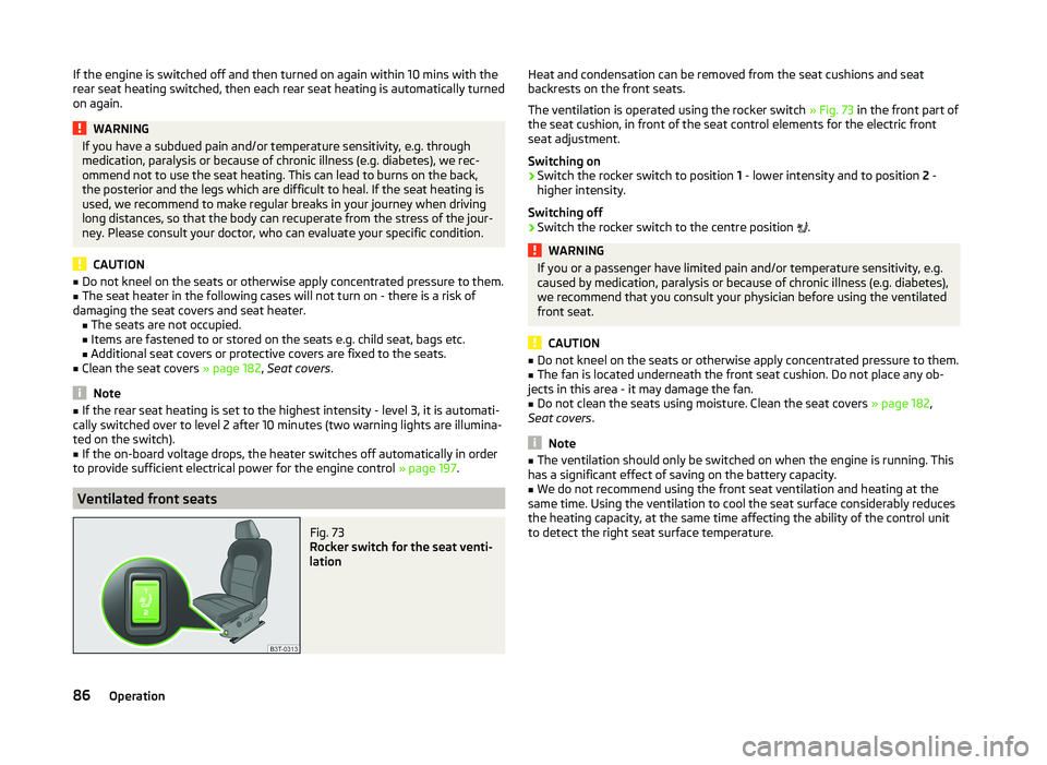
Rocker switch for the seat venti-
lation
Heat and condensation can be removed from the seat cushions and seat
backrests on the front seats.
The ventilation is operated using the rocker switch » Fig. 73 in the front part of
the seat cushion, in front of the seat control elements for the electric front
seat adjustment.
Switching on›
Switch the rocker switch to position 1 - lower intensity and to position 2 -
higher intensity.
Switching off
›
Switch the rocker switch to the centre position
.
WARNINGIf you or a passenger have limited pain and/or temperature sensitivity, e.g.
caused by medication, paralysis or because of chronic illness (e.g. diabetes),
we recommend that you consult your physician before using the ventilated
front seat.
CAUTION
■ Do not kneel on the seats or otherwise apply concentrated pressure to them.■The fan is located underneath the front seat cushion. Do not place any ob-
jects in this area - it may damage the fan.■
Do not clean the seats using moisture. Clean the seat covers » page 182,
Seat covers .
Note
■
The ventilation should only be switched on when the engine is running. This
has a significant effect of saving on the battery capacity.■
We do not recommend using the front seat ventilation and heating at the
same time. Using the ventilation to cool the seat surface considerably reduces
the heating capacity, at the same time affecting the ability of the control unit
to detect the right seat surface temperature.
86Operation
Page 95 of 252
WARNINGNever place flammable objects in the ashtray – risk of fire!
Note
The ashtrays are fitted with an interior light which illuminates when the park-
ing light is on.
12 Volt power outlet
Fig. 87
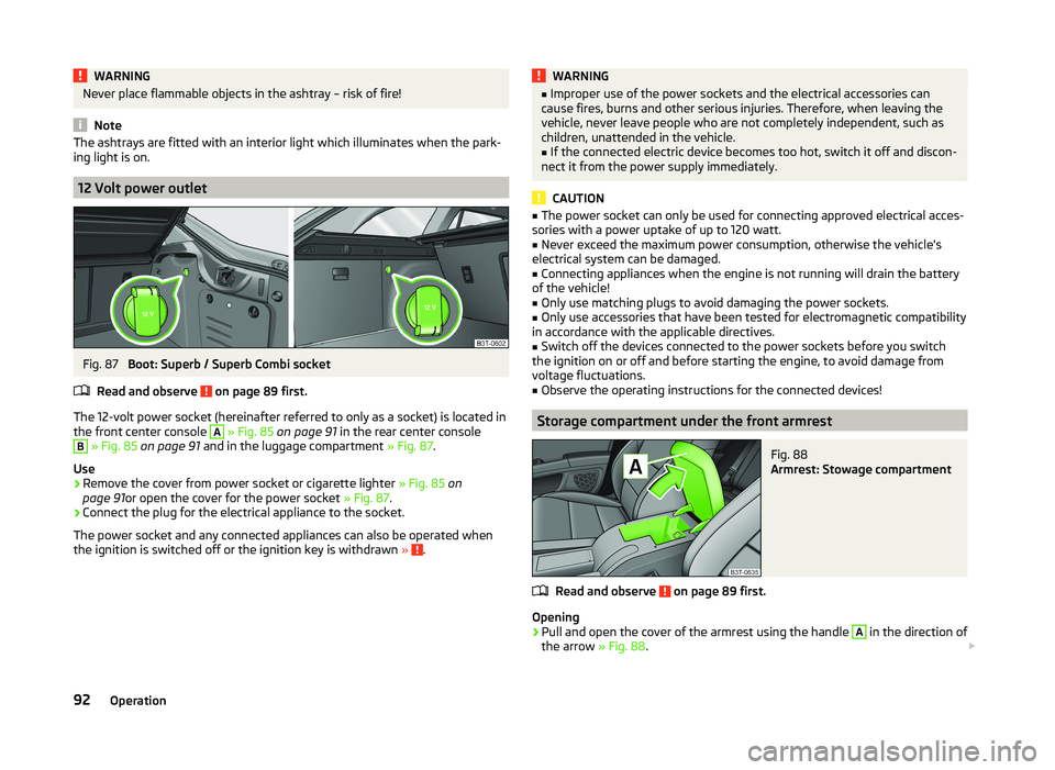
Boot: Superb / Superb Combi socket
Read and observe
on page 89 first.
The 12-volt power socket (hereinafter referred to only as a socket) is located in the front center console
A
» Fig. 85 on page 91 in the rear center console
B
» Fig. 85 on page 91 and in the luggage compartment » Fig. 87.
Use
›
Remove the cover from power socket or cigarette lighter » Fig. 85 on
page 91 or open the cover for the power socket » Fig. 87.
›
Connect the plug for the electrical appliance to the socket.
The power socket and any connected appliances can also be operated when
the ignition is switched off or the ignition key is withdrawn »
.
WARNING■
Improper use of the power sockets and the electrical accessories can
cause fires, burns and other serious injuries. Therefore, when leaving the
vehicle, never leave people who are not completely independent, such as
children, unattended in the vehicle.■
If the connected electric device becomes too hot, switch it off and discon-
nect it from the power supply immediately.
CAUTION
■ The power socket can only be used for connecting approved electrical acces-
sories with a power uptake of up to 120 watt.■
Never exceed the maximum power consumption, otherwise the vehicle's
electrical system can be damaged.
■
Connecting appliances when the engine is not running will drain the battery
of the vehicle!
■
Only use matching plugs to avoid damaging the power sockets.
■
Only use accessories that have been tested for electromagnetic compatibility
in accordance with the applicable directives.
■
Switch off the devices connected to the power sockets before you switch
the ignition on or off and before starting the engine, to avoid damage from
voltage fluctuations.
■
Observe the operating instructions for the connected devices!
Storage compartment under the front armrest
Fig. 88
Armrest: Stowage compartment
Read and observe on page 89 first.
Opening
›
Pull and open the cover of the armrest using the handle
A
in the direction of
the arrow » Fig. 88.
92Operation
Page 100 of 252
Removable ski bagFig. 98
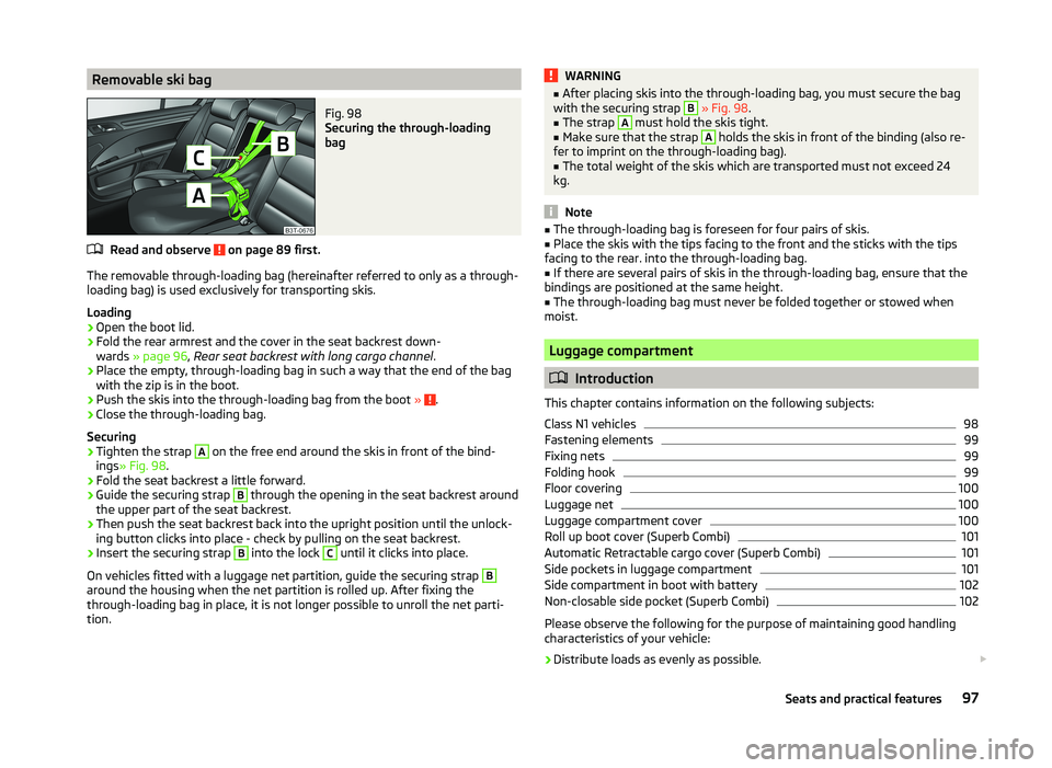
Securing the through-loading
bag
Read and observe on page 89 first.
The removable through-loading bag (hereinafter referred to only as a through- loading bag) is used exclusively for transporting skis.
Loading
›
Open the boot lid.
›
Fold the rear armrest and the cover in the seat backrest down-
wards » page 96 , Rear seat backrest with long cargo channel .
›
Place the empty, through-loading bag in such a way that the end of the bag
with the zip is in the boot.
›
Push the skis into the through-loading bag from the boot » .
›
Close the through-loading bag.
Securing
›
Tighten the strap
A
on the free end around the skis in front of the bind-
ings » Fig. 98 .
›
Fold the seat backrest a little forward.
›
Guide the securing strap
B
through the opening in the seat backrest around
the upper part of the seat backrest.
›
Then push the seat backrest back into the upright position until the unlock-
ing button clicks into place - check by pulling on the seat backrest.
›
Insert the securing strap
B
into the lock
C
until it clicks into place.
On vehicles fitted with a luggage net partition, guide the securing strap
B
around the housing when the net partition is rolled up. After fixing the
through-loading bag in place, it is not longer possible to unroll the net parti-
tion.
WARNING■ After placing skis into the through-loading bag, you must secure the bag
with the securing strap B » Fig. 98 .■
The strap
A
must hold the skis tight.
■
Make sure that the strap
A
holds the skis in front of the binding (also re-
fer to imprint on the through-loading bag).
■
The total weight of the skis which are transported must not exceed 24
kg.
Note
■ The through-loading bag is foreseen for four pairs of skis.■Place the skis with the tips facing to the front and the sticks with the tips
facing to the rear. into the through-loading bag.■
If there are several pairs of skis in the through-loading bag, ensure that the
bindings are positioned at the same height.
■
The through-loading bag must never be folded together or stowed when
moist.
Luggage compartment
Introduction
This chapter contains information on the following subjects:
Class N1 vehicles
98
Fastening elements
99
Fixing nets
99
Folding hook
99
Floor covering
100
Luggage net
100
Luggage compartment cover
100
Roll up boot cover (Superb Combi)
101
Automatic Retractable cargo cover (Superb Combi)
101
Side pockets in luggage compartment
101
Side compartment in boot with battery
102
Non-closable side pocket (Superb Combi)
102
Please observe the following for the purpose of maintaining good handling
characteristics of your vehicle:
›
Distribute loads as evenly as possible.
97Seats and practical features
Page 105 of 252
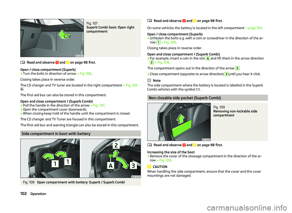
Fig. 107
Superb Combi boot: Open right
compartment
Read and observe and on page 98 first.
Open / close compartment (Superb)
›
Turn the bolts in direction of arrow » Fig. 106.
Closing takes place in reverse order.
The CD changer and TV tuner are located in the right compartment » Fig. 106
.
The first-aid box can also be stored in this compartment.
Open and close compartment / (Superb Combi)
›
Pull the handle in the direction of the arrow » Fig. 107.
›
Open the compartment cover downwards.
›
When closing keep hold of the handle until the compartment is closed.
The CD changer and TV Tuner are housed in this compartment.
The first-aid box and warning triangle can also be stored in this compartment.
Side compartment in boot with battery
Fig. 108
Open compartment with battery: Superb / Superb Combi
Read and observe and on page 98 first.
On some vehicles the battery is located in the left compartment » page 193.
Open / close compartment (Superb)
›
Unfasten the bolts e.g. with a coin or screwdriver in the direction of the ar-
row
1
» Fig. 108 .
Closing takes place in reverse order.
Open and close compartment / (Superb Combi)
›
For example, insert a coin in the slot
A
and lift them in the arrow direction
2
» Fig. 108 .
The compartment opens out in the direction of the arrow
3
.
›
Close compartment (opposite to arrow direction)
3
until you hear it click.
Note
The side compartment where the battery is located is labelled in the Superb
Combi vehicles with the symbol .
Non-closable side pocket (Superb Combi)
Fig. 109
Removing non-lockable side
compartment
Read and observe and on page 98 first.
Increasing the size of the boot
›
Remove the cover of the stowage compartment in the direction of the ar-
row » Fig. 109 .
CAUTION
When handling the side compartment, ensure that the cover and the cover
mountings are not damaged.102Operation
Page 121 of 252

NoteAs soon as the windscreen mists up, press the symbol button . Press the
button once the windscreen has demisted.
Controlling blower
The Climatronic system controls the blower stages automatically in line with
the interior temperature.
However, the blower stages can be manually adapted to suit your particular
needs.
›
Repeatedly pressing the symbol button on the left or right reduces or in-
creases blower speed.
If the blower is switched off, the Climatronic system is switched off.
The set blower speed is displayed above the symbol button when the re-
spective number of warning lights illuminate.
WARNING■ “Stale air” may result in fatigue in the driver and occupants, reduce atten-
tion levels and also cause the windows to mist up. The risk of having an ac-
cident increases.■
Do not switch off the Climatronic system for longer than necessary.
■
Switch on the Climatronic system as soon as the windows mist up.
Defrosting windscreen
Switching on
›
Press the
button » Fig. 126 on page 115 .
›
Press the
button » Fig. 126 on page 115 .
Switching off
›
Press the symbol button
again or press the symbol button
.
›
Press the
button again.
More air flows out of the air outlet vents 1 » Fig. 123 on page 110 . The tempera-
ture control is controlled automatically.
Auxiliary heating (auxiliary heating and ventilation)
Introduction
This chapter contains information on the following subjects:
Switching on/off
119
Radio remote control
120
Functional requirements of the auxiliary heating (auxiliary heating and ventila-
tion)
The charge state of the vehicle battery is sufficient.
The fuel supply is adequate (the warning icon is not lit in the display of
the instrument cluster).
Auxiliary ventilation
The auxiliary ventilation enables fresh air to flow into the vehicle interior by
switching off the engine, whereby the interior temperature is effectively de-
creased (e.g. with the vehicle parked in the sun).
Additional heating (hereinafter only as a aux. heating)
The auxiliary heating can be used when both when stationary, when the en-
gine is switched off, to preheat the vehicle and also while driving (e.g. during
the heating phase of the engine).
The aux. heating functions in connection with the air conditioning system or
Climatronic.
The auxiliary heating also warms up the engine. This is not valid for vehicles
with the 3.6 l/191 kW FSI engine.
The auxiliary heating warms up the coolant by combusting fuel from the vehi-
cle tank. This warms the air flowing into the passenger compartment (if the
blower is turned on).
Depending on the environmental conditions, the automatic on or off of the
heater occurs, which causes the best possible conditions for the engine run-
ning and the interior heating.
For vehicles with petrol engines, the automatic switching on and off of the
heater can be disabled at a specialist workshop.
118Operation
Page 122 of 252

WARNING■The auxiliary heating must never be operated in closed rooms (e.g. garag-
es) – risk of poisoning!■
The auxiliary heating must not be allowed to run during refuelling – risk
of fire.
■
The exhaust pipe of the auxiliary heating is located on the underside of
the vehicle. If you want to use the heater, then the car should not be
parked in places where the exhaust gases can come into contact with flam- mable materials such as dry grass, undergrowth, leaves, spilled fuel or simi-
lar - Risk of fire.
CAUTION
■ The running auxiliary heater consumes fuel from the vehicle tank and auto-
matically controls the filling level. If only a low quantity of fuel is present in the
fuel tank, the auxiliary heating switches off.■
The exhaust pipe of the auxiliary heating, which is located on the underside
of the vehicle, must not be clogged and the exhaust flow must not be blocked.
■
If the auxiliary heating is running, the vehicle battery discharges. If the auxili-
ary heating and ventilation has been operated several times over a longer peri-
od, the vehicle must be driven a few kilometres in order to recharge the vehi-
cle battery.
■
The air inlet in front of the windscreen must be free (e.g. of ice, snow or
leaves) to ensure that the auxiliary heating operates properly.
Note
■ The auxiliary heating switches on the blower B » Fig. 125 on page 112
or » Fig. 126 on page 115 only if it has achieved a coolant temperature of ap-
prox. 50 °C.■
At low outside temperatures, this can result in a formation of water vapour in
the area of the engine compartment. This is quite normal and is not an operat-
ing problem.
■
So that warm air can flow into the vehicle interior after switching on the aux-
iliary heating, you must maintain the comfort temperature normally selected
by you, leave the fan switched on and leave the air outlet vents in an open po-
sition. It is recommended to put the air flow in the position
or
.
Switching on/offFig. 127
Button for switching on/off the system directly on the operating
part of the air conditioning/Climatronic
Read and observe
and on page 119 first.
The auxiliary heating can be switched on/off as follows.
Manually switching on using the button on the operating part of the manual air conditioning/Cli-
matronic. The warning light in the button illuminates » Fig. 127.
by using the radio remote control » page 120.
Manually switching off using the button on the operating part of the manual air conditioning/Cli-
matronic. The warning light in the button goes out » Fig. 127,
by using the radio remote control » page 120.
After switching off the auxiliary heating, the coolant pump still runs for a short period.
Automatic switching on/off
The following menu items can be selected from the Aux. heating menu item in
the information display » page 47 (depending on the vehicle equipment):
■ Day of the week - set the current day of the week;
■ Running time - Set the required running time in 5 minute increments. The
running time can be 10 to 60 minutes.
■ Mode - Set the desired heating/ventilation mode;
119Air conditioning system
Page 123 of 252
■Starting time 1 , Starting time 2 , Starting time 3 - for each pre-set time, the
day and the time (hour and minute) can be set for switching on the auxiliary
heating. An empty position can be found between Sunday and Monday when
selecting the day. If this empty position is selected, the activation is per-
formed without taking into account the day.
■ Activate - Activate pre-set mode;
■ Deactivate - Deactivate pre-set mode;
■ Factory settings - Restore factory settings
■ Back - Return to main menu
Only one programmed pre-set time can be active.
The last programmed pre-set time remains active.
After the auxiliary heating activates automatically at the set time, it is neces-
sary to pre-set a time again.
If the menu item Back is selected or no changes are made on the display for
longer than 10 seconds, the set values are stored, but the pre-set time is not
activated.
The system switches itself off at the end of the running time set under the
menu item Running time .
Note
A warning light on the button » Fig. 127 illuminates when the system is run-
ning.
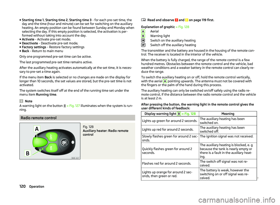
Radio remote control
Fig. 128
Auxiliary heater: Radio remote
control
Read and observe and on page 119 first.
Explanation of graphic » Fig. 128
Aerial
Warning light
Switch on the auxiliary heating
Switch off the auxiliary heating
The transmitter and the battery are housed in the housing of the remote con- trol. The receiver is located in the interior of the vehicle.
When the battery is fully charged, the range of the remote control is a few
hundred metres. Obstacles between the remote control and the vehicle, bad
weather conditions and a weaker battery in the remote control can clearly re-
duce the range.
To switch the auxiliary heating on or off, hold the remote control vertically,
with the aerial
A
pointing upwards. The antenna must not be covered with
the fingers or the palm of the hand during this process.
The auxiliary heating can only be switched on/off safely using the radio re-
mote control, if the distance between the radio remote control and the vehicle
is at least 2 m.
After pressing the button, the warning light in the remote control gives the
user different kinds of feedback:
Display warning light B » Fig. 128MeaningLights up green for around 2 seconds.The auxiliary heating has been
switched on.Lights up red for around 2 seconds.The auxiliary heating has been
switched off.Slowly flashes green for around 2 sec-
onds.The ignition signal was not received.Quickly flashes green for around 2
seconds.The auxiliary heating is blocked, e. g
because the tank is nearly empty or
there is a fault in the auxiliary heat-
ing.Flashes red for around 2 seconds.The switch off signal was not re-
ceived.Lights up orange for around 2 sec-
onds, then green or red.The battery is weak, however the
switching on or off signal was re-
ceived. AB120Operation
Page 124 of 252
Display warning light B » Fig. 128MeaningLights up orange for around 2 sec-
onds, then flashes green or red.The battery is weak, however the
switching on or off signal was not re-
ceived.Flashes orange for around 5 seconds.The battery is discharged, however
the switching on or off signal was not
received.
Replace the battery » page 216.
CAUTION
The radio remote control comprises electronic components and must therefore
be protected against water, severe impacts and direct sunlight.Communication and multimedia
General information
Introduction
This chapter contains information on the following subjects:
Mobile phones and two-way radio systems
121
Universal telephone preinstallation (hands-free)
122
Operating the phone on the multifunction steering wheel
122
Symbols in the MAXI DOT display
123
Phone Phonebook
124
Mobile phones and two-way radio systems
ŠKODA permits the operation of mobile phones and two-way radio systems
with a professionally installed external aerial and a maximum transmission
power of up to 10 watts.
Please ask at a specialist workshop about installing and operating mobile
phones and two-way radio systems that have a transmission power of more
than 10 W.
Operating mobile phones or two-way radio systems may interfere with the
functionality of the electronic systems in your vehicle.
This could be for the following reasons.
› no external aerial.
› external aerial incorrectly installed.
› transmission power greater than 10 watts.
WARNING■
If a mobile phone or a two-way radio system is operated in a vehicle with-
out an external aerial or an external aerial which has been installed incor-
rectly, this can increase the strength of the electromagnetic field inside the
vehicle.■
Two-way radio systems, mobile phones or mounts must not be installed
on airbag covers or within the immediate deployment range of the airbags.
121Communication and multimedia
Page 126 of 252
Button/wheel
» Fig. 129ActionFunction
1Press briefly(MUTE )1Turn upwardsIncrease volume1Turn downwardsDecrease volume2Press brieflyAccept a call/end a call
Display of the basic Phone menu → Main Phone menu → List of dialled numbers → Call selected contact2Press button for a long period
of timeReject the incoming call3Turn up/downPrevious / next menu item3Press brieflyConfirm selected menu item3Press button for a long periodof timeContinuously display first letter of the phone book3Quickly turn upwardsTo the previous initial letter in the telephone book3Quickly turn downwardsTo the next initial letter in the telephone book4Press brieflyReturn to previous level in the menu4Press button for a long periodof timeExit telephone menu
Symbols in the MAXI DOT display
SymbolMeaningValid forCharge status of the telephone battery a)GSM II, GSM IIISignal strengtha)GSM II, GSM IIIA phone is connected with the hands-free system.GSM II, GSM III when connected via the HFP profileThe hands-free system is visible to other devicesGSM II, GSM III when connected via the HFP profileA phone is connected with the hands-free system.GSM III when connected via the rSAP profileThe hands-free system is visible to other devicesGSM III when connected via the rSAP profileA multimedia unit is connected to the hands-free systemGSM II, GSM IIIA UMTS network is availableGSM IIIInternet connection via the hands-free systemGSM III when connected via the rSAP profilea)
This function is only supported by some mobile phones.
123Communication and multimedia
Page 141 of 252
Driving
Starting off and Driving
Starting and stopping the engine using the key
Introduction
This chapter contains information on the following subjects:
Electronic immobilizer
139
Ignition Switch
139
Starting the engine
139
Stopping the engine
140
Starting and stopping the engine on vehicles with the KESSY sys-
tem » page 140 .
The engine can only be started using a correctly coded original key.
The engine running noises may louder at first be louder for a short time after
starting the cold engine. This is quite normal and is not an operating problem.
WARNING■ When the vehicle is travelling with the engine off, the ignition key must
always be in position 2 » Fig. 134 on page 139 (ignition switched on). This
position is confirmed by the appearance of certain indicator lamps in the in-
strument cluster. ■If the key is not in position 2,
it could unexpectedly lock the steering -
danger of accident!
■
Only pull the ignition key from the ignition lock when the vehicle has
come to a complete stop (by applying the handbrake). Otherwise, the steer-
ing could be blocked – risk of accident!
■
Never leave the key in the vehicle when you exit the vehicle. Unauthor-
ized persons, such as children, for example, could lock the car, turn on the
ignition or start the engine - there is a danger of injury and accidents!
■
Never leave the vehicle unattended with the engine running - there is
risk of accident, damage or theft!
■
Never switch off the engine before the vehicle is stationary – risk of acci-
dent!
WARNING■ Never leave the engine running in unventilated or closed rooms. The en-
gine's exhaust gases also contain the odourless and colourless carbon
monoxide, a poisonous gas – risk of death. ■ Carbon monoxide can cause unconsciousness and death.■
Do not leave any items (e.g. cleaning cloths or tools) in the engine com-
partment. This presents a fire hazard and the risk of engine damage.
■
Never cover the engine with additional insulation material (e.g. with a
cover) – risk of fire!
CAUTION
■ The starter must only be operated when the engine is not running and the
vehicle is at a standstill. The starter or engine can be damaged if the starter is
activated when the engine is running 3
» Fig. 134 on page 139 .
■
Do not tow start the engine – there is a risk of damaging the engine and the
catalytic converter. The battery from another vehicle can be used as a jump-
start aid » page 211 , Jump-starting .
CAUTION
■
Avoid high engine revolutions, full throttle and high engine loads before the
engine has reached its operating temperature – risk of damaging the engine!■
Do not switch the engine off immediately at the end of your journey after the
engine has been operated over a prolonged period at high loads but leave it to
run at an idling speed for about 1 minute. This prevents any possible accumula-
tion of heat when the engine is switched off.
For the sake of the environment
Do not warm up the engine while the vehicle is stationary. If possible, start
your journey as soon as the engine has started. Through this the engine rea-
ches its operating temperature more rapidly and the pollutant emissions are
lower.
Note
After switching off the ignition, the radiator fan can intermittently continue to
operate for approx. 10 minutes.138Driving