buttons SKODA SUPERB 2010 Owner´s Manual
[x] Cancel search | Manufacturer: SKODA, Model Year: 2010, Model line: SUPERB, Model: SKODA SUPERB 2010Pages: 252, PDF Size: 16.33 MB
Page 32 of 252
Operation
Cockpit
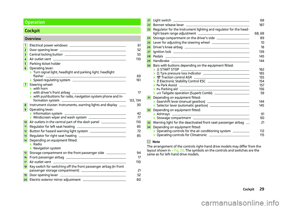
OverviewElectrical power windows
61
Door opening lever
52
Central locking button
55
Air outlet vent
110
Parking ticket holder
Operating lever: › Turn signal light, headlight and parking light, headlight
flasher
69
› Speed regulating system
161
Steering wheel:
› with horn
› with driver’s front airbag
17
› with pushbuttons for radio, navigation system phone and in-
formation system
122, 134
Instrument cluster: Instruments, warning lights and display
30
Operating lever:
› Information system
42
›Windscreen wiper and wash system
77
Air outlets in the central part of the dash panel
110
Regulator for left seat heating
85
Button for hazard warning light system
72
Regulator for right seat heating
85
Depending on equipment fitted:
› Radio
› Navigation system
Storage compartment on the front passenger side
94
Front passenger airbag
17
Air outlet vent
110
Key switch for switching off the front passenger airbag (in front
passenger storage compartment)
21
Door opening lever
52
Electric exterior mirror adjustment
801234567891011121314151617181920Light switch68
Bonnet release lever
187
Regulator for the instrument lighting and regulator for the head-
light beam range adjustment
68, 68
Storage compartment on the driver's side
89
Lever for adjusting the steering wheel
10
Driver’s knee airbag
18
Ignition lock
139
Pedals
145
Handbrake
144
Bars with buttons depending on the equipment fitted:
›
START STOP
162
›
Tyre pressure loss indicator
165
›
Traction control ASR
155
›
Electronic Stability Control ESC
154
›
Park Assist
157
›
Parking aid
156
›
Tailgate operation (Superb Combi)
59
Depending on equipment fitted:
› Gearshift lever (manual gearbox)
144
›Selector lever (automatic gearbox)
145
Depending on equipment fitted:
› Ashtrays
91
›Stowage compartment
90
Warning light for the deactivated front seat passenger airbag
21
Depending on equipment fitted:
› Operating controls for the air conditioning system
112
›
Operating controls for Climatronic
115
Note
The arrangement of the controls right-hand drive models may differ from the
layout shown in » Fig. 20. The symbols on the controls and switches are the
same as for left-hand drive models.212223242526272829303132333429Cockpit
Page 35 of 252
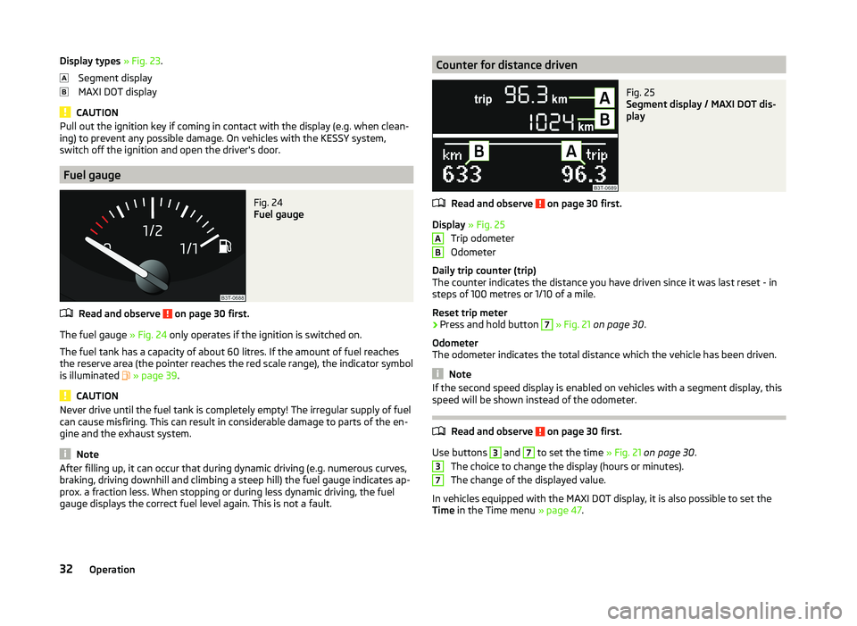
Display types » Fig. 23 .
Segment display
MAXI DOT display
CAUTION
Pull out the ignition key if coming in contact with the display (e.g. when clean-
ing) to prevent any possible damage. On vehicles with the KESSY system,
switch off the ignition and open the driver's door.
Fuel gauge
Fig. 24
Fuel gauge
Read and observe on page 30 first.
The fuel gauge » Fig. 24 only operates if the ignition is switched on.
The fuel tank has a capacity of about 60 litres. If the amount of fuel reaches the reserve area (the pointer reaches the red scale range), the indicator symbol
is illuminated
» page 39 .
CAUTION
Never drive until the fuel tank is completely empty! The irregular supply of fuel
can cause misfiring. This can result in considerable damage to parts of the en-
gine and the exhaust system.
Note
After filling up, it can occur that during dynamic driving (e.g. numerous curves,
braking, driving downhill and climbing a steep hill) the fuel gauge indicates ap-
prox. a fraction less. When stopping or during less dynamic driving, the fuel
gauge displays the correct fuel level again. This is not a fault.Counter for distance drivenFig. 25
Segment display / MAXI DOT dis-
play
Read and observe on page 30 first.
Display » Fig. 25
Trip odometer
Odometer
Daily trip counter (trip)
The counter indicates the distance you have driven since it was last reset - in
steps of 100 metres or 1/10 of a mile.
Reset trip meter
›
Press and hold button
7
» Fig. 21 on page 30 .
Odometer
The odometer indicates the total distance which the vehicle has been driven.
Note
If the second speed display is enabled on vehicles with a segment display, this
speed will be shown instead of the odometer.
Read and observe on page 30 first.
Use buttons
3
and
7
to set the time » Fig. 21 on page 30 .
The choice to change the display (hours or minutes).
The change of the displayed value.
In vehicles equipped with the MAXI DOT display, it is also possible to set the
Time in the Time menu » page 47.
AB3732Operation
Page 45 of 252
Information system
Driver information system
Introduction
This chapter contains information on the following subjects:
Using the information system
42
Display a low temperature
43
Gear recommendation
43
Door, boot or engine compartment warning
44
The information system provides the driver with alerts and messages about in-
dividual vehicle systems.
This information and advice is shown in the instrument cluster display or indi-
cated by the illumination of the corresponding warning light in the instrument
cluster.
The information system provides the following information and instructions
(depending on vehicle equipment).
› Data relating to the multi function display (MFD)
» page 44.
› Data relating to the MAXI DOT display
» page 46.
› Service interval display
» page 48.
› Auto Check Control
» page 33.
› Selector lever positions for an automatic transmission
» page 145.
WARNINGConcentrate fully at all times on your driving! As the driver, you are fully re-
sponsible for the operation of your vehicle.Using the information systemFig. 27
Buttons / wheel: on the operating lever / on the multifunction
steering wheel
Read and observe
on page 42 first.
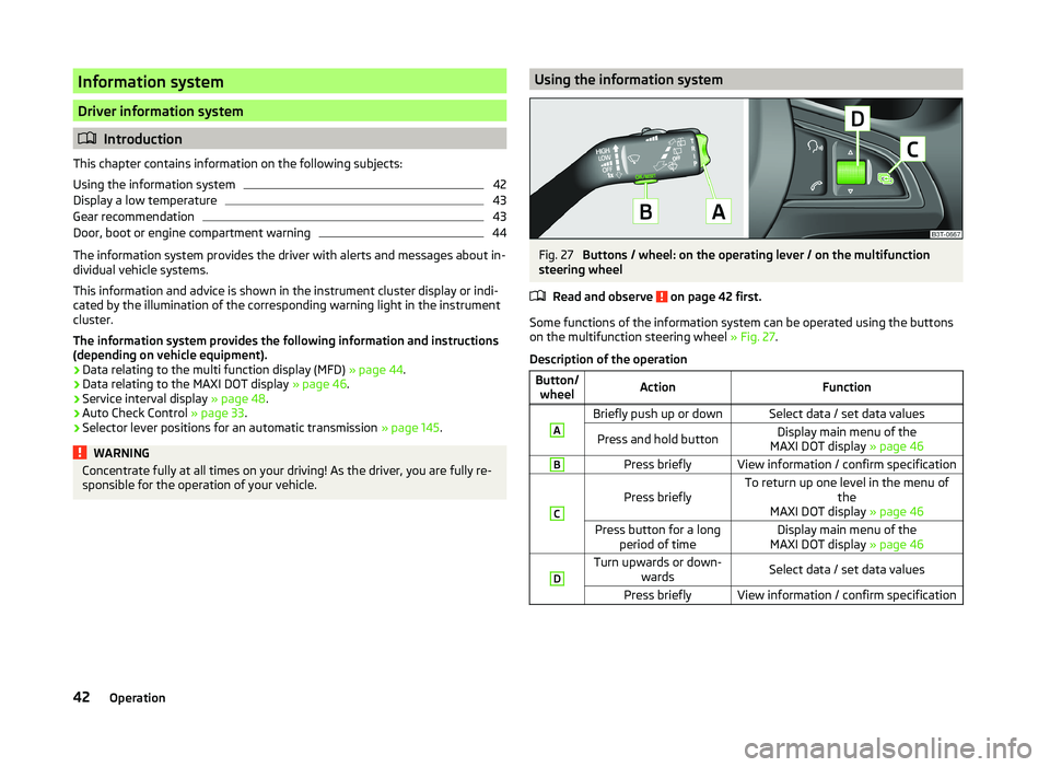
Some functions of the information system can be operated using the buttons
on the multifunction steering wheel » Fig. 27.
Description of the operation
Button/ wheelActionFunctionABriefly push up or downSelect data / set data valuesPress and hold buttonDisplay main menu of the
MAXI DOT display » page 46BPress brieflyView information / confirm specificationC
Press brieflyTo return up one level in the menu of
the
MAXI DOT display » page 46Press button for a long
period of timeDisplay main menu of the
MAXI DOT display » page 46DTurn upwards or down-
wardsSelect data / set data valuesPress brieflyView information / confirm specification42Operation
Page 58 of 252
Locking/unlocking the vehicle from the insideFig. 35
Central locking button
Read and observe on page 51 first.
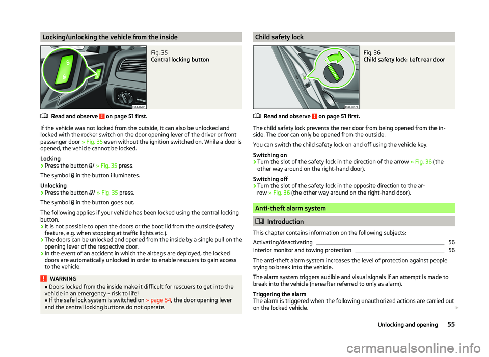
If the vehicle was not locked from the outside, it can also be unlocked and
locked with the rocker switch on the door opening lever of the driver or front
passenger door » Fig. 35 even without the ignition switched on. While a door is
opened, the vehicle cannot be locked.
Locking
›
Press the button /
» Fig. 35 press.
The symbol in the button illuminates.
Unlocking
›
Press the button /
» Fig. 35 press.
The symbol in the button goes out.
The following applies if your vehicle has been locked using the central locking
button.
› It is not possible to open the doors or the boot lid from the outside (safety
feature, e.g. when stopping at traffic lights etc.).
› The doors can be unlocked and opened from the inside by a single pull on the
opening lever of the respective door.
› In the event of an accident in which the airbags are deployed, the locked
doors are automatically unlocked in order to enable rescuers to gain access
to the vehicle.
WARNING■ Doors locked from the inside make it difficult for rescuers to get into the
vehicle in an emergency – risk to life!■
If the safe lock system is switched on » page 54, the door opening lever
and the central locking buttons do not operate.
Child safety lockFig. 36
Child safety lock: Left rear door
Read and observe on page 51 first.
The child safety lock prevents the rear door from being opened from the in- side. The door can only be opened from the outside.
You can switch the child safety lock on and off using the vehicle key.
Switching on
›
Turn the slot of the safety lock in the direction of the arrow » Fig. 36 (the
other way around on the right-hand door).
Switching off
›
Turn the slot of the safety lock in the opposite direction to the ar-
row » Fig. 36 (the other way around on the right-hand door).
Anti-theft alarm system
Introduction
This chapter contains information on the following subjects:
Activating/deactivating
56
Interior monitor and towing protection
56
The anti-theft alarm system increases the level of protection against people
trying to break into the vehicle.
The alarm system triggers audible and visual signals if an attempt is made to
break into the vehicle (hereafter referred to only as alarm).
Triggering the alarm
The alarm is triggered when the following unauthorized actions are carried out
on the locked vehicle.
55Unlocking and opening
Page 65 of 252
WARNING■Ensure that no persons are still left in the vehicle when locking the vehi-
cle. In an emergency, the windows will no longer be able to be opened from
the inside.■
The system is fitted with a force limiter » page 63. If there is an obsta-
cle, the closing process is stopped and the window goes down by several
centimetres. The windows should nevertheless be closed carefully – risk of
injury.
■
Deactivating the electrically operated power windows in the rear doors is
recommended (safety push button)
S
when children are being transported
in the rear seats » Fig. 44 on page 62 .
CAUTION
■
Keep the windows clean to ensure the correct functionality of the electric
windows.■
In the event that the windows are frozen, first of all eliminate the
ice » page 179 , Windows and exterior mirrors and only then operate the elec-
trical power windows. Otherwise, the window sealing and the electrical power
window mechanism could be damaged.
■
In the winter, ice accumulating on the surface of the window may cause
there to be more resistance when closing the window. The window will stop
and move back several centimetres.
■
It is necessary to deactivate the force limiter to close the win-
dow » page 63 .
■
Always make sure that the windows are closed when you leave the locked
vehicle.
For the sake of the environment
At high speeds, you should keep the windows closed to prevent unnecessarily high fuel consumption.Note■ After switching the ignition off, it is still possible to open or close the win-
dows for approx. 10 minutes. After the driver's or front passenger's door has
been opened, the windows can only be operated by using button A
» Fig. 44
on page 62 .
■
When driving always use the existing heating, air conditioning and ventila-
tion system for ventilating the interior of the vehicle. If the windows are
opened, dust as well as other dirt can get into the vehicle and in addition the
wind noise is more at certain speeds.
■
The window lift system is equipped with protection against overheating. Re-
peated opening and closing of the window can cause this mechanism to over-
heat. If this happens, it will not be possible to operate the window for a short
time. You will be able to operate the window again as soon as the overheating
protection has cooled down.
Opening/closing the window from the driver seat
Fig. 44
Buttons on the driver's door
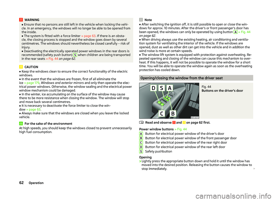
Read and observe and on page 62 first.
Power window buttons » Fig. 44
Button for electrical power window of the driver's door
Button for electrical power window of the front passenger door
Button for electrical power window of the rear right door
Button for electrical power window of the rear left door
Safety pushbutton
Opening
›
Lightly press the appropriate button down and hold it until the window has
moved into the desired position. Releasing the button causes the window to
stop immediately.
ABCDS62Operation
Page 66 of 252

The window can be completely opened automatically by briefly pressing the
button as far as the stop. Renewed pressing of the button causes the window
to stop immediately.
Closing›
Pull gently on the top edge of the corresponding button and hold until the
window has moved into the desired position. Releasing the button causes
the window to stop immediately.
The window can also be fully closed automatically by pulling the button up to the stop. Renewed pulling of the button causes the window to stop immedi-
ately.
Safety pushbutton
The buttons for power windows in the rear doors can be deactivated by press-
ing the safety switch
S
» Fig. 44 . The buttons for the electrical power win-
dows at the rear doors are activated again by pressing the safety push button
S
again.
If the buttons for the rear doors are deactivated, the warning light in the
safety switch
S
illuminates.
Opening the windows in the front passenger door and in the rear
doors
Fig. 45
Button in the rear door
Read and observe and on page 62 first.
There is a button in the front passenger door and in the rear doors for that
window.
Opening
›
Lightly press the appropriate button down and hold it until the window has
moved into the desired position. Releasing the button causes the window to
stop immediately.
The window can be completely opened automatically by briefly pressing the
button as far as the stop. Renewed pressing of the button causes the window
to stop immediately.
Closing›
Pull gently on the top edge of the corresponding button and hold until the
window has moved into the desired position. Releasing the button causes
the window to stop immediately.
The window can also be fully closed automatically by pulling the button up to the stop. Renewed pulling of the button causes the window to stop immedi-
ately.
Force limit
Read and observe
and on page 62 first.
The electrical power window system is fitted with a force limiter. It reduces
the risk of bruises or injuries when closing the windows.
If there is an obstacle, the closing process is stopped and the window goes
down by several centimetres.
If the obstacle prevents the window from being closed during the next 10 sec-
onds, the closing process is interrupted once again and the window goes down
by several centimetres.
If you attempt to close the window again within 10 seconds of the window be-
ing moved down for the second time, even though the obstacle was not yet
been removed, the closing process is only stopped. During this time it is not
possible to automatically close the window. The force limiter is still switched
on.
The force limiter is only switched off if you attempt to close the window again
within the next 10 seconds - the window will now close with full force!
If you wait longer than 10 seconds, the force limiter is switched on again.
Window convenience operation
Read and observe
and on page 62 first.
The convenience operation of the windows offers the possibility of opening or
closing all the windows at once.
Convenience operation can take place in one of the following ways.
63Unlocking and opening
Page 69 of 252

downwards and hold forwards firmly. The sliding/tilting roof opens and closes
again after around 10 seconds. Do not release the control dial until it has done
so.■
If, for example, the battery has been disconnected and reconnected, it is pos-
sible that the sun screen does not operate correctly. Then turn the switch to
position
A
» Fig. 47 on page 66 and press and hold the button
G
» Fig. 48 on
page 66 . The sun screen opens and closes again after around 10 seconds. Do
not release the control dial until it has done so.
Operation
Fig. 47
Control dial for the sliding/tilting
roof
Read and observe on page 65 first.
Comfort position
›
Turn the switch to position
C
» Fig. 47 .
When the sliding/tilting roof is in the comfort position, the intensity of the
wind noise is reduced.
Open partially
›
Turn the switch to a position in area
D
.
Open fully
›
Turn the switch to position
B
and hold it in this position (spring-tensioned
position).
Tilting roof
›
Turn the switch to position
A
.
›
Press the switch in the region
E
towards the roof.
Closing
›
Turn the switch to position
A
.
›
Press the switch on the recess
E
down and pull forwards.
Force limiter
The sliding/tilting roof is fitted with a force limiter. The sliding/tilting roof
stops and moves back several centimetres when it cannot be closed because
there is something in the way (e.g. ice). The sliding/tilting roof can be fully
closed without a force limiter by pressing the switch on the recess E
down
and then pushing it forward until the sliding/tilting roof is fully closed » .
WARNINGWhen operating the sliding/tilting roof, proceed with caution to avoid caus-
ing crushing injuries – risk of injury!
CAUTION
During the winter it may be necessary to remove any ice and snow in the vicin-
ity of the sliding/tilting roof before opening it to prevent any damage to the
opening mechanism.
Opening/closing the sun screen
Fig. 48
Buttons for sun screen
Read and observe on page 65 first.
The sun screen can be closed or opened using the buttons » Fig. 48.
Opening
›
Briefly press the button
F
» Fig. 48 to open fully.
›
Press and hold the button
F
to open to the desired position.
The opening process stops when one releases the button.
Closing
›
Briefly press the button
G
» Fig. 48 to close fully.
›
Press and hold the button
G
to close in the desired position.
The closing process stops when one releases the button.
66Operation
Page 78 of 252
NoteIf the door is open and the ignition switched off, the light extinguishes auto-
matically after around 20 minutes.
Entry lighting
The lighting is positioned on the bottom edge of the exterior mirror and illumi-
nates the entry area of the front door.
The light illuminates after the vehicle has been unlocked or on opening the
front door. The lighting goes out about 30 seconds after the doors are closed
or if the ignition is switched on.
WARNINGIf the entry light is on, do not touch its cover – risk of burns!
Note
If the door is open and the ignition switched off, the light will extinguish auto-
matically after around 1 minute.
Visibility
Introduction
This chapter contains information on the following subjects:
Windscreen and rear window heater
75
Sun visors
76
Sun screen
76
Sun screen in the rear doors
76Windscreen and rear window heaterFig. 58
Buttons for the rear and front window heating Climatronic / man-
ual air conditioning
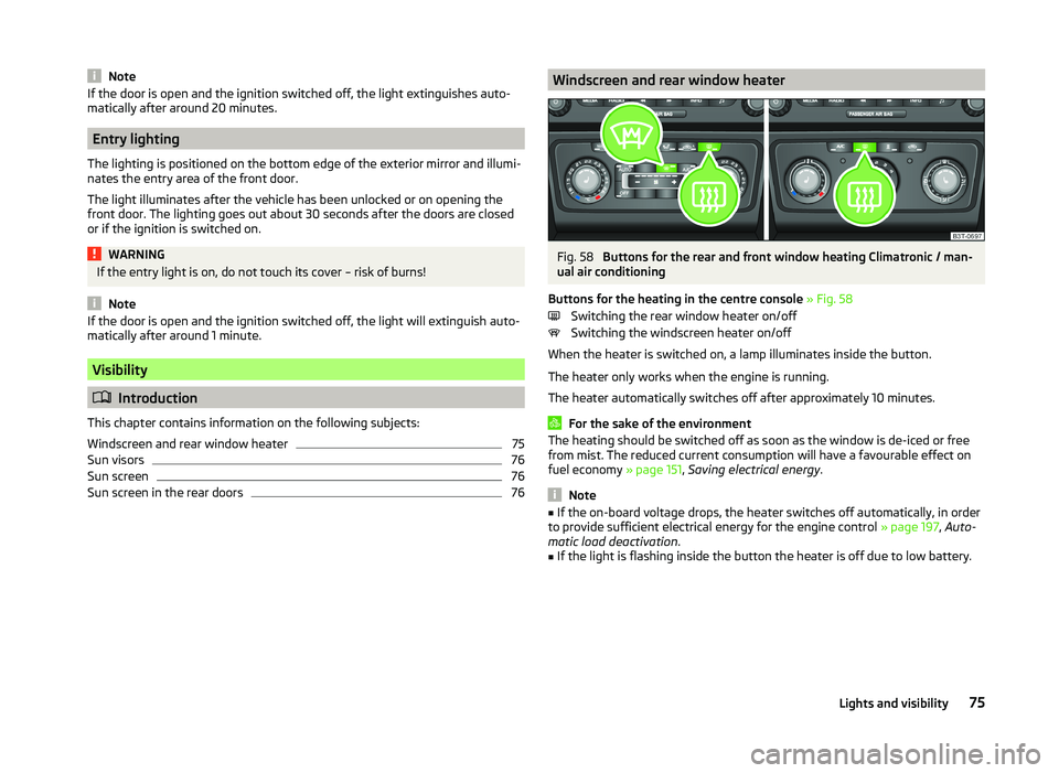
Buttons for the heating in the centre console » Fig. 58
Switching the rear window heater on/off
Switching the windscreen heater on/off
When the heater is switched on, a lamp illuminates inside the button.
The heater only works when the engine is running.
The heater automatically switches off after approximately 10 minutes.
For the sake of the environment
The heating should be switched off as soon as the window is de-iced or free
from mist. The reduced current consumption will have a favourable effect on
fuel economy » page 151, Saving electrical energy .
Note
■
If the on-board voltage drops, the heater switches off automatically, in order
to provide sufficient electrical energy for the engine control » page 197, Auto-
matic load deactivation .■
If the light is flashing inside the button the heater is off due to low battery.
75Lights and visibility
Page 87 of 252
Memory function of the electrically adjustable seatFig. 71
Memory buttons and SET button
Read and observe on page 81 first.
The memory function for the driver's seat provides the option to store the po-
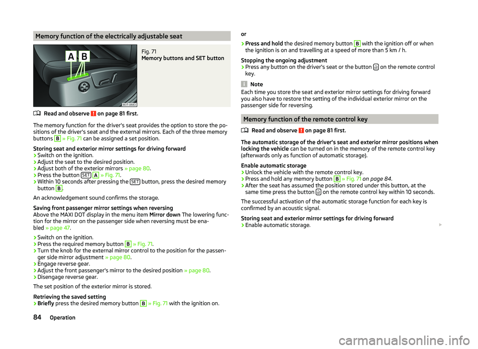
sitions of the driver's seat and the external mirrors. Each of the three memory
buttons
B
» Fig. 71 can be assigned a set position.
Storing seat and exterior mirror settings for driving forward
›
Switch on the ignition.
›
Adjust the seat to the desired position.
›
Adjust both of the exterior mirrors » page 80.
›
Press the button SET
A
» Fig. 71 .
›
Within 10 seconds after pressing the SET button, press the desired memory
button
B
.
An acknowledgement sound confirms the storage.
Saving front passenger mirror settings when reversing
Above the MAXI DOT display in the menu item Mirror down The lowering func-
tion for the mirror on the passenger side when reversing must be ena-
bled » page 47 .
›
Switch on the ignition.
›
Press the required memory button
B
» Fig. 71 .
›
Turn the knob for the external mirror control to the position for the passen-
ger side mirror adjustment » page 80.
›
Engage reverse gear.
›
Adjust the front passenger's mirror to the desired position » page 80.
›
Disengage reverse gear.
The set position of the exterior mirror is stored.
Retrieving the saved setting
›
Briefly press the desired memory button
B
» Fig. 71 with the ignition on.
or›
Press and hold the desired memory button
B
with the ignition off or when
the ignition is on and travelling at a speed of more than 5 km / h.
Stopping the ongoing adjustment
›
Press any button on the driver's seat or the button on the remote control
key.
Note
Each time you store the seat and exterior mirror settings for driving forward
you also have to restore the setting of the individual exterior mirror on the
passenger side for reversing.
Memory function of the remote control key
Read and observe
on page 81 first.
The automatic storage of the driver's seat and exterior mirror positions when
locking the vehicle can be turned on in the memory of the remote control key
(afterwards only as function of automatic storage).
Enable automatic storage
›
Unlock the vehicle with the remote control key.
›
Press and hold any memory button
B
» Fig. 71 on page 84 .
›
After the seat has assumed the position stored under this button, at the
same time press the button on the remote control key within 10 seconds.
The successful activation of the automatic storage function for each key is
confirmed by an acoustic signal.
Storing seat and exterior mirror settings for driving forward
›
Enable automatic storage.
84Operation
Page 109 of 252

The variable loading floor can be pulled out a little more before dividing the
boot with the variable loading floor » page 105. This enlarges the space be-
tween the rear seats and the separation.
CAUTION
Ensure that the raised front edge of the variable loading floor is not damaged.
Fit and remove variable loading floor
Fig. 115
Luggage compartment: fold up variable loading floor
Fig. 116
Luggage compartment: variable loading floor
Read and observe
on page 105 first.
The variable loading floor can be removed and reinstalled, if necessary.
Removing
›
Grasp the rear part of the floor by the handle, raise it slightly in the direction
of the arrow
1
» Fig. 115 and pull it out over the bumper in the direction of
the arrow
2
until it engages in the opening
C
» Fig. 116 .
›Fold up the loading floor by moving it in the direction of the arrow3» Fig. 115
.›
Press the safety buttons
A
» Fig. 116 and remove the floor.
Fitting
›
Fold up the floor and place it on the carrier rails.
›
Push the floor forwards until it engages in the openings
B
in the carrier
rails » Fig. 116 .
›
Carefully press in the vicinity of the openings
C
on the floor until it clicks in-
to place, if necessary press the safety buttons
A
.
WARNINGEnsure the variable loading floor is attached correctly during installation. If
this is not the case, there is a risk of injury for the occupants.
Fixing set
Fig. 117
Telescopic pole and tensioning strap
Read and observe
on page 105 first.
The fixing set can be used for dividing the boot or for securing the objects
which are being transported.
Telescopic pole
›
Insert the holders for the telescopic pole into the left and right openings of
the carrier rails.
›
Press the top part of the holder in the direction of the arrow
1
» Fig. 117 and
simultaneously push in the desired position in the direction of the arrow
2
.
›
Ensure that the holder is correctly locked in place.
106Operation