key battery SKODA SUPERB 2010 Owner´s Manual
[x] Cancel search | Manufacturer: SKODA, Model Year: 2010, Model line: SUPERB, Model: SKODA SUPERB 2010Pages: 252, PDF Size: 16.33 MB
Page 43 of 252
Airbag systemRead and observe
on page 35 first.
If the warning light
illuminates , there is a fault in the airbag system.
The following message is shown in the MAXI DOT display. Fault: Airbag
The operational capability of the airbag system is monitored electronically,
even if one of the airbags is switched off.
If a front, side or head airbag or belt tensioner has been switched off using
the vehicle system tester:
› The warning light
illuminates for approximately 4 seconds after the igni-
tion is switched on and then flashes again for approximately 12 seconds.
The following message is shown in the MAXI DOT display. Airbag/belt tensioner deactivated.
If the front passenger's front airbag was switched off using the key-operat-
ed switch on the side of the dash panel on the passenger side:
› The warning light
illuminates for approximately 4 seconds after the igni-
tion is switched on;
› The deactivated air bag is indicated by the illumination of the warning light
in the middle of the dash panel
» page 21.
WARNINGWhen a fault in the airbag system occurs, there is a risk of the system not
being triggered in the event of an accident. Therefore, this must be
checked immediately by a specialized company.
Tyre inflation pressure
Read and observe
on page 35 first.
The warning light is illuminated
If while driving, the warning light illuminates, a tyre pressure change has oc-
curred.
An audible signal sounds as a warning signal.
›
Immediately reduce speed and avoid sudden steering and braking manoeu-
vres.
› Stop the vehicle, turn the ignition off and check the tyres and their inflation
pressure » page 198 .›
Correct the tyre pressure, if necessary or replace the wheel » page 205 or
use the repair kit » page 209.
›
Store the tyre pressure values in the system » page 166.
The warning light
flashes for about 1 min. and remains lit
If the warning light
flashes for approximately 1 minute and stays on, there
may be a fault in the tyre pressure monitoring system.
›
Stop the vehicle, turn the ignition off and start the engine again.
If the warning light
flashes again after the engine has started, there is a
system error.
Seek help from a specialist garage.
The following reasons can explain the warning light being illuminated.
› The vehicle is loaded on one side. Distribute loads as evenly as possible.
› The wheels of one axle are loaded more heavily (e.g. when towing a trailer or
when driving uphill or downhill).
› Snow chains are mounted.
› A wheel has been changed.
Store the tyre pressure values in the system » page 166.
CAUTION
Under certain circumstances (e.g. sporty style of driving, wintry or unpaved
roads) the warning light in the instrument cluster can be delayed or does
not light up at all.
Note
The warning light illuminates after the ignition is switched on if the vehi-
cle's battery has been disconnected and reconnected. If the warning light does
not go out after moving a short distance, this means that there is an error in
the system. Seek help from a specialist garage.
Windscreen washer fluid level
Read and observe
on page 35 first.
If the windscreen washer fluid level is too low, the warning light
illumi-
nates .
40Operation
Page 54 of 252
›The warning light in the driver door begins flashing.
› The anti-theft alarm system is activated.
Displaying an error If the warning icon in the driver's door initially flashes quickly for around 2 sec-
onds, and then illuminates for 30 seconds without interruption before flashing
again slowly, you will need to seek the assistance of a specialist garage.WARNING■ Never leave the key in the vehicle when you exit the vehicle. Unauthor-
ized persons, such as children, for example, could lock the car, turn on the
ignition or start the engine - there is a danger of injury and accidents!■
When leaving the vehicle, never leave people who are not completely in-
dependent, such as children, unattended in the vehicle. The children might,
for example, release the handbrake or take the vehicle out of gear. The ve-
hicle could then start to move – risk of injury and accidents! These individu-
als might also not be able to leave the vehicle on their own or to help
themselves. Can be fatal at very high or very low temperatures!
■
If the car is locked from the outside and the safe lock system is switched
on, no one must be in the car, as it is then not possible to open either a
door or a window from the inside. The locked doors make it more difficult
for rescuers to get into the vehicle in an emergency – risk to life.
Note
■ When leaving the vehicle, always check if it is locked.■In the event of an accident in which the airbags are deployed, the locked
doors are automatically unlocked in order to enable rescuers to gain access to
the vehicle.■
Upon failure of the central locking system the key can only be used to unlock
and lock the driver's door. The other doors and the boot lid can be emergency
opened or emergency released. ■ Emergency locking of the door » page 216.
■ Emergency unlocking of the boot lid » page 217.
Vehicle keyFig. 31
Remote control key
Read and observe on page 51 first.
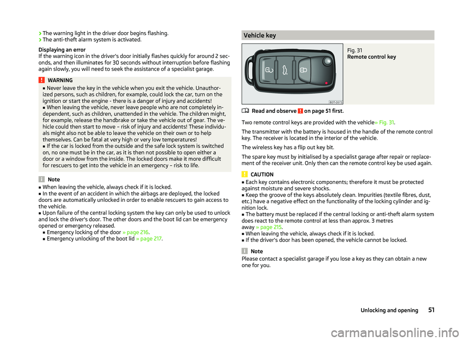
Two remote control keys are provided with the vehicle » Fig. 31.
The transmitter with the battery is housed in the handle of the remote control
key. The receiver is located in the interior of the vehicle.
The wireless key has a flip out key bit.
The spare key must by initialised by a specialist garage after repair or replace- ment of the receiver unit. Only then can the remote control key be used again.
CAUTION
■ Each key contains electronic components; therefore it must be protected
against moisture and severe shocks.■
Keep the groove of the keys absolutely clean. Impurities (textile fibres, dust,
etc.) have a negative effect on the functionality of the locking cylinder and ig-
nition lock.
■
The battery must be replaced if the central locking or anti-theft alarm system
does react to the remote control at less than approx. 3 metres
away » page 215 .
■
When leaving the vehicle, always check if it is locked.
■
If the driver's door has been opened, the vehicle cannot be locked.
Note
Please contact a specialist garage if you lose a key as they can obtain a new
one for you.51Unlocking and opening
Page 55 of 252
Unlocking/locking with the remote control keyFig. 32
Remote control key
Read and observe on page 51 first.
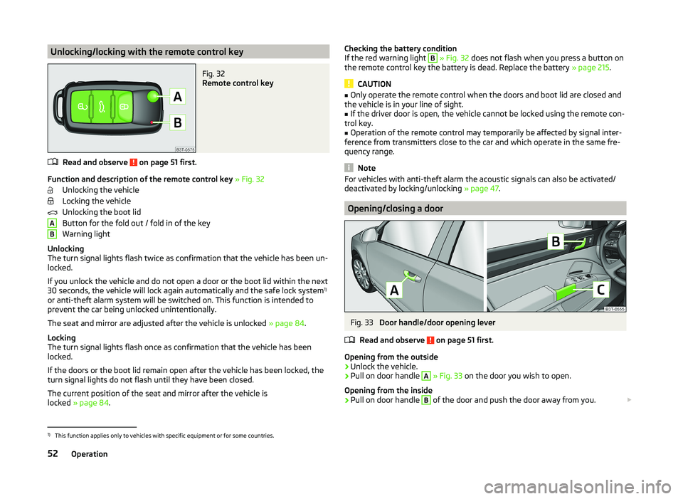
Function and description of the remote control key » Fig. 32
Unlocking the vehicle
Locking the vehicle
Unlocking the boot lid
Button for the fold out / fold in of the key
Warning light
Unlocking
The turn signal lights flash twice as confirmation that the vehicle has been un-
locked.
If you unlock the vehicle and do not open a door or the boot lid within the next
30 seconds, the vehicle will lock again automatically and the safe lock system 1)
or anti-theft alarm system will be switched on. This function is intended to prevent the car being unlocked unintentionally.
The seat and mirror are adjusted after the vehicle is unlocked » page 84.
Locking
The turn signal lights flash once as confirmation that the vehicle has been
locked.
If the doors or the boot lid remain open after the vehicle has been locked, the
turn signal lights do not flash until they have been closed.
The current position of the seat and mirror after the vehicle is
locked » page 84 .
ABChecking the battery condition
If the red warning light B » Fig. 32 does not flash when you press a button on
the remote control key the battery is dead. Replace the battery » page 215.
CAUTION
■
Only operate the remote control when the doors and boot lid are closed and
the vehicle is in your line of sight.■
If the driver door is open, the vehicle cannot be locked using the remote con-
trol key.
■
Operation of the remote control may temporarily be affected by signal inter-
ference from transmitters close to the car and which operate in the same fre-
quency range.
Note
For vehicles with anti-theft alarm the acoustic signals can also be activated/
deactivated by locking/unlocking » page 47.
Opening/closing a door
Fig. 33
Door handle/door opening lever
Read and observe
on page 51 first.
Opening from the outside
›
Unlock the vehicle.
›
Pull on door handle
A
» Fig. 33 on the door you wish to open.
Opening from the inside
›
Pull on door handle
B
of the door and push the door away from you.
1)
This function applies only to vehicles with specific equipment or for some countries.
52Operation
Page 56 of 252
Closing from the inside›Grasp pull handle C and close the door.WARNING■Make sure that the door has closed correctly as it can open suddenly
while the vehicle is being driven – there is a risk of death.■
Only open and close the door when there is no one in the opening/closing
sweep – there is a risk of injury.
■
An opened door can close spontaneously if there is a strong wind or the
vehicle is on a slope – there is a risk of injury.
■
Never drive with the doors open - there is a risk of death!
Unlocking / locking - KESSY
Fig. 34
Sensors in the handle of the
front door
Read and observe on page 51 first.
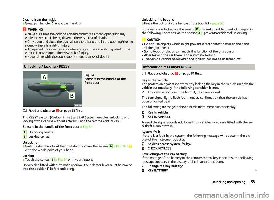
The KESSY system (Keyless Entry Start Exit System) enables unlocking and
locking of the vehicle without actively using the remote control key.
Sensors in the handle of the front door » Fig. 34
Unlocking sensor
Locking sensor
Unlocking
›
Grab the door handle of the front door or cover the sensor
A
» Fig. 34 » with the whole palm of your hand.
Locking
›
Touch the sensor
B
» Fig. 34 with your fingers.
On vehicles fitted with automatic gearbox, the selector lever must be moved
into the position P before unlocking.
ABUnlocking the boot lid›Press the button in the handle of the boot lid » page 57.
If the vehicle is locked via the sensor B
, it is not possible to unlock it again in
the following 2 seconds via the sensor
A
- prevents accidental unlocking.
CAUTION
■ Do not use objects which might prevent direct contact between the hand
and the grip sensor.■
Some types of gloves can impair the function of the grip sensor.
■
After leaving the car there is no automatic locking.
■
The vehicle cannot be locked if the ignition has not been turned off.
Information messages KESSY
Read and observe
on page 51 first.
Key in the vehicle
The protection against inadvertently locking the key in the vehicle unlocks the
vehicle automatically if the following condition is met.
The vehicle, including the boot lit, has been locked.
The turn signal lights flash four times as confirmation that the vehicle has
been unlocked again.
The following message is shown in the instrument cluster display. Key in vehicle.
KEY IN VEHICLE
An audible signal sounds additionally on vehicles which are fitted with the an-
ti-theft alarm system, .
System fault
If there is a fault in the system, the following message will appear in the dis-
play of the instrument cluster.
Keyless access system faulty.
CHECK KEYLESS
Low voltage of the key battery
If the voltage of the battery in the remote control key is too low, the following
message appears in the display of the instrument cluster.
Change the key battery!
KEY BATTERY
53Unlocking and opening
Page 57 of 252
Change the key battery » page 215!
Safe securing
Read and observe
on page 51 first.
The door locks are blocked automatically if the vehicle is locked from the out-side. The vehicle cannot now be opened from the inside.
This fact is pointed out by the following message on the display of the instru- ment cluster after switching off the ignition.
Check SAFELOCK! Owner's manual!
CHECK DEADLOCK
Switching off
The safe lock can be switched off in one of the following ways.
›
By locking twice within 2 seconds.
›
By disabling the interior monitoring » page 56, Interior monitor and towing
protection .
If the vehicle is locked and the SafeLock system is switched off, the door can be opened separately from the inside by a single pull on the opening lever.
Switching on
The safelock switches on automatically the next time the vehicle is locked and
unlocked.
Switch on display
The warning light flashes for around 2 seconds in quick succession, afterwards
it begins to flash evenly at longer intervals.
Switch off display
The warning light in the driver door flashes fast for about 2 seconds, goes out
and starts to flash regularly at longer intervals after about 30 seconds.
WARNINGIf the car is locked and the SafeLock system activated, no one may remain
in the car as it will then not be possible to either unlock a door or open a
window from the inside. The locked doors make it more difficult for rescu-
ers to get into the vehicle in an emergency – risk to life!NoteThis function applies only to vehicles with specific equipment or for some
countries.
Individual settings
Read and observe
on page 51 first.
The following central locking functions can be set via the MAXI DOT dis-
play » page 47 , Settings .
Opening a single door
This function makes it possible to only unlock the driver's door. The other
doors and the boot lid remain locked and are only unlocked after being opened
again.
Unlocking a vehicle side door
This function enables you to unlock both doors on the driver's side. The other
doors and the boot lid remain locked and are only unlocked after being opened
again.
Automatic locking/unlocking
All doors are locked from a speed of around 15 km/h. The button in the handle
of the boot lid is deactivated.
If the ignition key is withdrawn, the car is then automatically unlocked again.
In addition, it is possible for the driver or front passenger to unlock the car by
pressing the central locking button .
Locked doors prevent unwanted entry into the vehicle.
The vehicle doors can be unlocked and opened at any time by pulling once on
the door opening lever.
54Operation
Page 64 of 252
Acoustic signalsRead and observe
and on page 59 first.
The acoustic signals serve as a safety function and provide information about
the success of a performed action.
SignalsMeaning
Interrupted tone
Open (using the button on the remote control key
or the button C
» Fig. 43 on page 60 )
Automatic closing of the lid » page 59,
in section In-
troduction
1 continuous toneForce limiter3 rising tonesConfirmation of the storage of the lid position3 identical tonesfault
Adjusting/deleting the top lid position
Read and observe
and on page 59 first.
Adjusting
›
Stop the lid in the desired position (electrically or manually).
›
Press and hold the button
B
» Fig. 42 on page 59 for longer than 3 seconds.
Storing the new position is confirmed with an audible signal.
Delete
›
Carefully lift up the lid manually to the maximum opening position.
›
Press and hold the button
B
» Fig. 42 on page 59 for longer than 3 seconds.
An audible signal sounds and the height which was originally set is deleted
from the memory, while the basic position of the top lid position is again set.
The top lid position is adjusted, for example, in the following situations.
› When the space for opening the lid is limited (e.g. garage height).
› For a more convenient operation, such as by a person's height.
The top position which is reached when the lid opens automatically, is always
lower than the maximum top position which can be reached when the lid is
opened manually.
The lid always opens to the height which was last stored.
Malfunctions
Read and observe
and on page 59 first.
If the battery is disconnected and reconnected while the lid is open, it is nec-
essary to activate the system of the electric boot lid.
Activation means closing the lid by hand. Thus, the end position of the lid is stored under fully closed in secured lock.
Examples of operational malfunctions
Description of the malfunc-
tionPossible solutionsThe lid cannot be lifted out
of the lockEmergency unlocking of the lid » page 217The lid does not react to an
opening signalRemoving a possible obstacle (e.g. snow), re-
opening the lid » page 59
Press handle A
and pull the lid upwards
The lid remains in the top
positionManual closing of the lid
Electrical power windows
Introduction
This chapter contains information on the following subjects:
Opening/closing the window from the driver seat
62
Opening the windows in the front passenger door and in the rear doors
63
Force limit
63
Window convenience operation
63
Operational faults
64
61Unlocking and opening
Page 67 of 252

Opening›Press and hold the symbol button on the remote control key.›
Hold the key in the driver's lock in the unlock position.
›
Press and hold the upper part of the central locking button in the driver's
door » page 55 .
›
Hold button
A
» Fig. 44 on page 62 in the opening position.
Closing
›
Press and hold the symbol button
on the remote control key.
›
Hold the key in the driver's lock in the lock position.
›
Press and hold the lower part of the central locking button » page 55 in the
driver's door.
›
Hold button
A
» Fig. 44 on page 62 in the closing position.
›
In the KESSY system, hold a finger on the sensor
B
» Fig. 34 on page 53 .
The speed limit for winter tyres can be set in the MAXI DOT display in the
menu item Window op. . » page 47 .
The prerequisite for ensuring that the convenience operating feature correctly
is the automatic opening/closing of all windows is operational.
Convenience opening or closing the window using the key in the driver's lock
is only possible within 45 seconds after locking the vehicle.
The movement of the window is stopped immediately when the key or the re-
spective button is released.
Operational faults
Read and observe
and on page 62 first.
The automatic power windows do not work if the vehicle battery has been dis-
connected and connected again while a window was open. The system must
be activated.
Activation sequence:
›
Switch on the ignition.
›
Pull the top edge of the button and close the window.
›
Release the button.
›
Drag and drop the button upwards again and hold for about 1 s.
Electric sliding/tilting roof
Introduction
This chapter contains information on the following subjects:
Operation
64
Convenience operation of sliding / tilting roof
65
Electric sliding/tilting roof with solar cells
65
The electric sliding/tilting roof (abbreviated in the following as 'sliding/tilting
roof') can only be operated when the ignition is turned on and when the out-
door temperature is higher than -20 °C.
The sliding/tilting roof can still be operated for approx. 10 minutes after
switching the ignition off. However, as soon as the driver or front passenger's
door is opened it is no longer possible to operate the sliding/tilting roof.
CAUTION
■ Always close the sliding/tilting roof before disconnecting the battery.■If the battery has been disconnected and reconnected, it is possible that the
sliding/tilting roof does not operate correctly. In this case, turn the rotary
switch to the switch position A
» Fig. 46 on page 64 and push forward for
about 10 seconds.
Operation
Fig. 46
Control dial for the sliding/tilting
roof
Read and observe on page 64 first.
Comfort position
›
Turn the switch to position
C
» Fig. 46 .
When the sliding/tilting roof is in the comfort position, the intensity of the
wind noise is reduced.
64Operation
Page 68 of 252

Open partially›Simply turn the knob to a point between A and C.
Open fully
›
Turn the switch to position
B
and hold it in this position (spring-tensioned
position).
Tilting roof
›
Turn the switch to position
D
.
Closing
›
Turn the switch to position
A
.
Sun screen
The sun screen is also opened automatically when the tilt/slide sunroof slides
open. When the tilt/slide sunroof is closed the sun screen can be manually op-
erated »
.
Force limiter
The sliding/tilting roof is fitted with a force limiter. If an obstacle (e.g. ice) pre-
vents closing, the sliding/tilting roof stops and opens completely. The sliding/
tilting roof can be closed completely without the force limiter by pushing the
switch in position
A
» Fig. 46 forwards until the sliding/tilting roof is com-
pletely closed.
WARNINGWhen operating the tilt/slide sunroof and the sunshade, proceed with cau-
tion to avoid causing crushing injuries – risk of injury!
CAUTION
During the winter it may be necessary to remove any ice and snow in the vicin-
ity of the sliding/tilting roof before opening it to prevent any damage to the
opening mechanism.
Convenience operation of sliding / tilting roof
Read and observe
on page 64 first.
The sliding/tilting roof can be operated by locking/unlocking using the key or
using the KESSY system with the aid of the sensor
B
» Fig. 34 on page 53 .
›
Press and hold the symbol button
on the remote control key.
›
In the KESSY system, hold a finger on the sensor
B
» Fig. 34 on page 53 .
By releasing the lock or lifting your finger off the sensor B when using the
KESSY system, the closing process is immediately interrupted.WARNINGClose the sliding/tilting roof carefully – risk of injury. The force limiter does
not operate with the convenience closing.
Electric sliding/tilting roof with solar cells
Read and observe
on page 64 first.
If there is sufficient bright sunlight, the solar cells in the sliding/tilting roof de-liver the electrical power for the fresh air blower. Further informa-
tion » page 115 , Climatronic (automatic air conditioning system) .
The operation of the sliding/tilting roof with solar cells is the same as of a nor-
mal sliding/tilting roof.
Panoramic sliding/tilting roof (Superb Estate)
Introduction
This chapter contains information on the following subjects:
Operation
66
Opening/closing the sun screen
66
Convenience operation of sliding / tilting roof
67
The panoramic sliding/tilting roof (abbreviated in the following as 'sliding/tilt-
ing roof') can only be operated when the ignition is turned on and when the
outdoor temperature is higher than -20 °C.
The sliding/tilting roof can still be operated for approx. 10 minutes after
switching the ignition off. However, as soon as the driver or front passenger's
door is opened it is no longer possible to operate the sliding/tilting roof.
CAUTION
■ Always close the sliding/tilting roof before disconnecting the battery.■If, for example, the battery has been disconnected and reconnected, it is pos-
sible that the sliding/tilting roof does not operate correctly. Next, move the ro-
tary switch into position A
» Fig. 47 on page 66 , pull the recess firmly
65Unlocking and opening
Page 76 of 252
WARNINGSwitch on the hazard warning light system if, for example, the following oc-
curs.■
You encounter a traffic jam.
■
The vehicle has broken down.
Parking lights
Read and observe
on page 67 first.
The parking light is designed for temporary lighting of the parked vehicle.
Switching on the parking light
›
Switch off the ignition.
›
Place the control lever into position
A
or
B
as far as it can go » Fig. 50 on
page 69 - the parking light on the right/left-hand side of the vehicle is
switched on.
If the right or left turn signal light has been switched on and the ignition is
switched off, the parking light is not automatically switched on.
Switching on the side lights on both sides
›
Switch off the ignition.
›
Turn the light switch
A
to position
» Fig. 49 on page 68 and lock the ve-
hicle.
After pulling out the ignition key and opening the driver's door, an audible
warning sounds. After a few seconds or after closing the driver's door, the au-
dible alarm is turned off, but the parking lights will remain switched on.
CAUTION
Turning on the parking light means the battery is heavily loaded, especially
over short distances.
Interior lights
Introduction
This chapter contains information on the following subjects:
Front interior light
73
Rear interior light - Variant 1
74
Rear interior light - Variant 2
74Front door warning light74Entry lighting75
Note
With the ignition off, the light turns off automatically after about 10 minutes.
Front interior light
Fig. 54
Operation of the front interior light: Version 1/version 2
Rocker switch positions » Fig. 54
Switching on
Switching off
Control with the door contact switch (middle position)
There is no icon available for the center position (operation with the door con-
tact switch) in Version 2.
Switch for reading lights Switching left reading lamp on/off
Switching right reading lamp on/off
Conditions for operation of light with the door contact switch - setting
The system is turned on when any of the following is present.
› The vehicle is unlocked.
› One of the doors or the luggage compartment lid is being opened.
› The ignition key is removed.
The system is turned off when any of the following is present.
› The vehicle is locked.
› The ignition is switched on.
› About 30 seconds after all the doors have been closed.
73Lights and visibility
Page 95 of 252
WARNINGNever place flammable objects in the ashtray – risk of fire!
Note
The ashtrays are fitted with an interior light which illuminates when the park-
ing light is on.
12 Volt power outlet
Fig. 87
Boot: Superb / Superb Combi socket
Read and observe
on page 89 first.
The 12-volt power socket (hereinafter referred to only as a socket) is located in the front center console
A
» Fig. 85 on page 91 in the rear center console
B
» Fig. 85 on page 91 and in the luggage compartment » Fig. 87.
Use
›
Remove the cover from power socket or cigarette lighter » Fig. 85 on
page 91 or open the cover for the power socket » Fig. 87.
›
Connect the plug for the electrical appliance to the socket.
The power socket and any connected appliances can also be operated when
the ignition is switched off or the ignition key is withdrawn »
.
WARNING■
Improper use of the power sockets and the electrical accessories can
cause fires, burns and other serious injuries. Therefore, when leaving the
vehicle, never leave people who are not completely independent, such as
children, unattended in the vehicle.■
If the connected electric device becomes too hot, switch it off and discon-
nect it from the power supply immediately.
CAUTION
■ The power socket can only be used for connecting approved electrical acces-
sories with a power uptake of up to 120 watt.■
Never exceed the maximum power consumption, otherwise the vehicle's
electrical system can be damaged.
■
Connecting appliances when the engine is not running will drain the battery
of the vehicle!
■
Only use matching plugs to avoid damaging the power sockets.
■
Only use accessories that have been tested for electromagnetic compatibility
in accordance with the applicable directives.
■
Switch off the devices connected to the power sockets before you switch
the ignition on or off and before starting the engine, to avoid damage from
voltage fluctuations.
■
Observe the operating instructions for the connected devices!
Storage compartment under the front armrest
Fig. 88
Armrest: Stowage compartment
Read and observe on page 89 first.
Opening
›
Pull and open the cover of the armrest using the handle
A
in the direction of
the arrow » Fig. 88.
92Operation