Console SKODA SUPERB 2012 2.G / (B6/3T) Owner's Manual
[x] Cancel search | Manufacturer: SKODA, Model Year: 2012, Model line: SUPERB, Model: SKODA SUPERB 2012 2.G / (B6/3T)Pages: 235, PDF Size: 5.86 MB
Page 10 of 235
Instruments and Indicator Lights
Instrument Cluster
ä
Introduction
This chapter contains information on the following subjects:
Overview of the Instrument cluster 8
Engine revolutions counter 9
9
Coolant temperature gauge 9
Fuel gauge 9
Counter for distance driven 10
Service Interval Display 10
Digital clock 11
Recommended gear 11
Display in rear centre console 12
WARNING
■ Concentrate fully at all times on your driving! As the driver you are fully re-
sponsible for the operation of your vehicle.
■ Never operate the controls in the instrument cluster while driving, only
when the vehicle is stationary! Ð Overview of the Instrument cluster
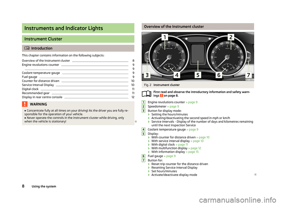
Fig. 2
Instrument cluster
First read and observe the introductory information and safety warn-
ings on page 8.
Engine revolutions counter
» page 9
Speedometer » page 9
Button for display mode:
› Setting the hours/minutes
› Activating/deactivating the second speed in mph or km/h
› Service intervals - Display of the number of days and kilometres remaining
until the next Inspection Service
Coolant temperature gauge » page 9
Display:
› With counter for distance driven
» page 10
› With service interval display
» page 10
› With digital clock
» page 11
› With multifunction display
» page 12
› With information display » page 15
Fuel gauge » page 9
Button for:
› Reset trip counter for the distance driven
› Resetting Service Interval Display
› Set hours/minutes
› Activate/deactivate display mode Ð
ä 1
2
3
4
5
6
7
8
Using the system
Page 14 of 235
Display in rear centre console
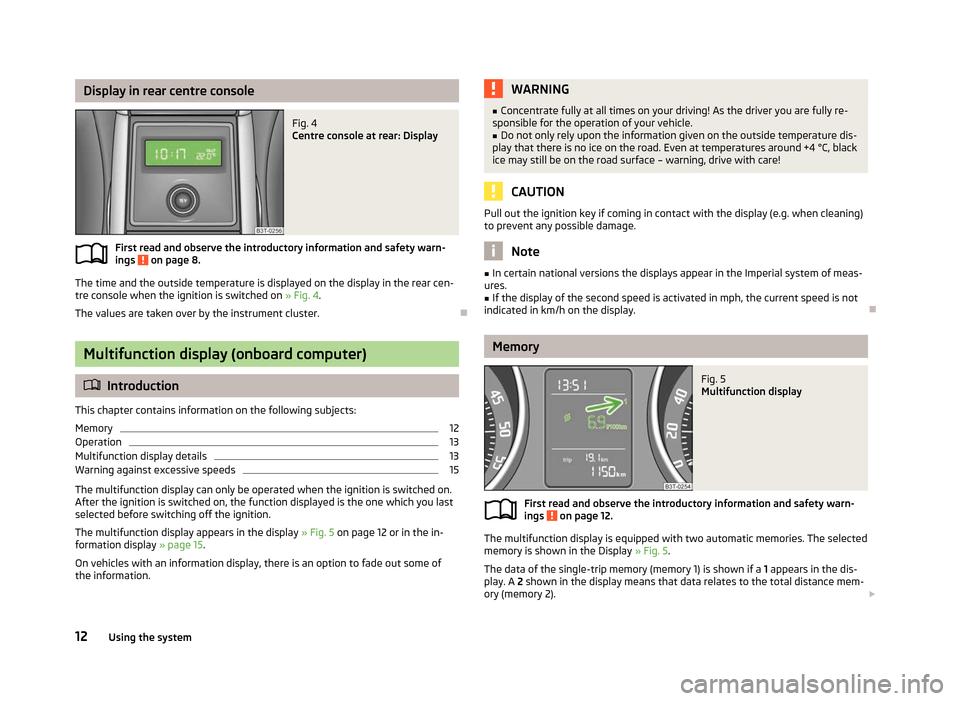
Fig. 4
Centre console at rear: Display
First read and observe the introductory information and safety warn-
ings on page 8.
The time and the outside temperature is displayed on the display in the rear cen-
tre console when the ignition is switched on » Fig. 4.
The values are taken over by the instrument cluster. ÐMultifunction display (onboard computer)
ä
Introduction
This chapter contains information on the following subjects:
Memory 12
Operation 13
Multifunction display details 13
Warning against excessive speeds 15
The multifunction display can only be operated when the ignition is switched on.
After the ignition is switched on, the function displayed is the one which you last
selected before switching off the ignition.
The multifunction display appears in the display » Fig. 5
on page 12 or in the in-
formation display » page 15.
On vehicles with an information display, there is an option to fade out some of
the information. ä WARNING
■ Concentrate fully at all times on your driving! As the driver you are fully re-
sponsible for the operation of your vehicle.
■ Do not only rely upon the information given on the outside temperature dis-
play that there is no ice on the road. Even at temperatures around +4 °C, black
ice may still be on the road surface – warning, drive with care! CAUTION
Pull out the ignition key if coming in contact with the display (e.g. when cleaning)
to prevent any possible damage. Note
■ In certain national versions the displays appear in the Imperial system of meas-
ures. ■ If the display of the second speed is activated in mph, the current speed is not
indicated in km/h on the display. Ð Memory
Fig. 5
Multifunction display
First read and observe the introductory information and safety warn-
ings on page 12.
The multifunction display is equipped with two automatic memories. The selected
memory is shown in the Display » Fig. 5.
The data of the single-trip memory (memory 1) is shown if a 1 appears in the dis-
play. A 2 shown in the display means that data relates to the total distance mem-
ory (memory
2). £
ä
12 Using the system
Page 40 of 235
Electric boot lid
ä
Introduction
This chapter contains information on the following subjects:
Preliminary information 38
Description of the operation 39
Audible signals 39
Adjusting the top position of the lid 40
Operational problems 40
Ð Preliminary information
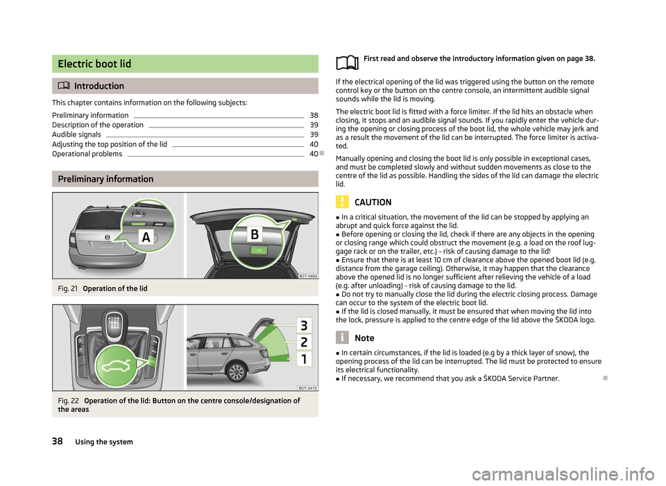
Fig. 21
Operation of the lid Fig. 22
Operation of the lid: Button on the centre console/designation of
the areas First read and observe the introductory information given on page
38. If the electrical opening of the lid was triggered using the button on the remote
control key or the button on the centre console, an intermittent audible signal
sounds while the lid is moving.
The electric boot lid is fitted with a force limiter. If the lid hits an obstacle when
closing, it stops and an audible signal sounds. If you rapidly enter the vehicle dur-
ing the opening or closing process of the boot lid, the whole vehicle may jerk and
as a result the movement of the lid can be interrupted. The force limiter is activa-
ted.
Manually opening and closing the boot lid is only possible in exceptional cases,
and must be completed slowly and without sudden movements as close to the
centre of the lid as possible. Handling the sides of the lid can damage the electric
lid.
CAUTION
■ In a critical situation, the movement of the lid can be stopped by applying an
abrupt and quick force against the lid.
■ Before opening or closing the lid, check if there are any objects in the opening
or closing range which could obstruct the movement (e.g. a load on the roof lug-
gage rack or on the trailer, etc.) - risk of causing damage to the lid!
■ Ensure that there is at least 10 cm of clearance above the opened boot lid (e.g.
distance from the garage ceiling). Otherwise, it may happen that the clearance
above the opened lid is no longer sufficient after relieving the vehicle of a load
(e.g. after unloading) - risk of causing damage to the lid. ■ Do not try to manually close the lid during the electric closing process. Damage
can occur to the system of the electric boot lid.
■ If the lid is closed manually, it must be ensured that when moving the lid into
the lock, pressure is applied to the centre edge of the lid above the ŠKODA logo. Note
■ In certain circumstances, if the lid is loaded (e.g by a thick layer of snow), the
opening process of the lid can be interrupted. The lid must be protected to ensure
its electrical functionality. ■ If necessary, we recommend that you ask a ŠKODA Service Partner. Ð
ä
38 Using the system
Page 41 of 235
Description of the operation
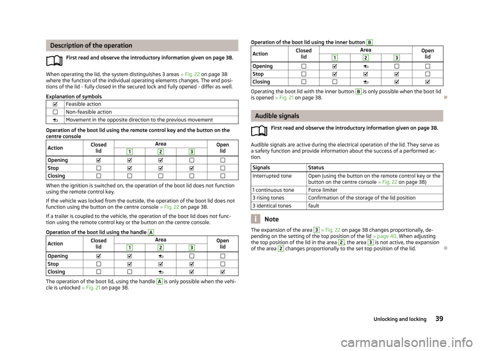
First read and observe the introductory information given on page 38.When operating the lid, the system distinguishes 3 areas » Fig. 22 on page 38
where the function of the individual operating elements changes. The end posi-
tions of the lid - fully closed in the secured lock and fully opened - differ as well.
Explanation of symbols
Feasible action
Non-feasible action
Movement in the opposite direction to the previous movement Operation of the boot lid using the remote control key and the button on the
centre console
Action Closed
lid Area
Open
lid 1 2 3
Opening
Stop
Closing When the ignition is switched on, the operation of the boot lid does not function
using the remote control key.
If the vehicle was locked from the outside, the operation of the boot lid does not
function using the button on the centre console » Fig. 22 on page 38.
If a trailer is coupled to the vehicle, the operation of the boot lid does not func-
tion using the remote control key or the button on the centre console.
Operation of the boot lid using the handle A
Action
Closed
lid Area
Open
lid 1 2 3
Opening
Stop
Closing The operation of the boot lid, using the handle A
is only possible when the vehi-
cle is unlocked » Fig. 21 on page 38.
ä
Operation of the boot lid using the inner button B
Action
Closed
lid Area
Open
lid 1 2 3
Opening
Stop
Closing Operating the boot lid with the inner button B
is only possible when the boot lid
is opened » Fig. 21 on page 38. Ð Audible signals
First read and observe the introductory information given on page
38. Audible signals are active during the electrical operation of the lid. They serve as
a safety function and provide information about the success of a performed ac-
tion.
Signals Status
Interrupted tone Open (using the button on the remote control key or the button on the centre console » Fig. 22 on page 38)
1 continuous tone Force limiter
3 rising tones Confirmation of the storage of the lid position
3 identical tones fault Note
The expansion of the area 3
» Fig. 22 on page 38 changes proportionally, de-
pending on the setting of the top position of the lid »
page 40. When adjusting
the top position of the lid in the area 2
, the area 3
is not active, the expansion
of the area 2
changes proportionally to the set top position of the lid.
Ð
ä
39
Unlocking and locking
Page 84 of 235

Attachment points
Fig. 81
Attachment points for roof bars
First read and observe the introductory information and safety warn-
ings on page 81.
Perform the assembly and disassembly according to the enclosed instructions.
CAUTION
Observe the information regarding the assembly and disassembly in the enclosed
instructions. Note
The figure only applies to Combi vehicles. ÐRoof load
First read and observe the introductory information and safety warn-
ings on page 81.
The maximum permissible roof load (including roof rack system) of
100 kg and the
maximum permissible total weight of the vehicle should not be exceeded.
The full permissible roof load cannot be used if a roof rack system with a lower
load carrying capacity is used. In this case, the roof rack system must only be loa-
ded up to the maximum weight limit specified in the fitting instructions. Ð
ä
ä Cup holder
ä
Introduction
This chapter contains information on the following subjects:
Cup holder in front centre console 82
Cup holder in the rear armrest 83
WARNING
■ Never put hot beverage containers in the cup holder. If the vehicle moves,
they may spill - risk of scalding!
■ Do not use any cups or beakers which are made of brittle material (e.g. glass,
porcelain). This could lead to injuries in the event of an accident. CAUTION
■ Do not leave open beverage containers in the cup holder during the journey.
There is a risk of spilling e.g. when braking which may cause damage to the elec-
trical components or seat upholstery.
■ Slide in the cup holder before raising the armrest. Ð Cup holder in front centre console
Fig. 82
Front centre console: Cup holder
First read and observe the introductory information and safety warn-
ings on page 82.
Two beverage containers can be placed into the recesses
» Fig. 82.£
ä
82 Using the system
Page 85 of 235

On vehicles that are fitted with a cover for cup holders, you can cover the cup
holder by pulling on the handle
A
.
ÐCup holder in the rear armrest
Fig. 83
Rear armrest: Cup holder/insert cup holder
First read and observe the introductory information and safety warn-
ings on page 82.
Two beverage containers can be placed into the cup holder.
›
Press on the front end of the armrest in the direction of the arrow
» Fig. 83 - ,
the cup holder comes out.
› To slide the cup holder in again, press the middle part of the cup hold-
er » Fig. 83 - and slide it into the armrest. Ð
ä Ashtray
Fig. 84
Centre console: Ashtray at the front/rear
Removing the front ashtray insert › Open the ashtray
» Fig. 90 on page 86.
› Grasp the ashtray insert in the area A
» Fig. 84
and remove it in the direction
of the arrow.
Inserting the front ashtray insert
› Insert the ashtray vertically downwards.
Removing the rear ashtray insert
› Open the ashtray
»
Fig. 98 on page 89.
› Grasp the ashtray insert B
» Fig. 84
in the area marked with the arrows and
remove it.
Inserting the rear ashtray insert
› Place the ashtray insert in the mount and press it in. WARNING
Never place flammable objects in the ashtray - risk of fire! Ð
83
Seats and Stowage
Page 86 of 235

Cigarette lighter, 12-volt power socket
Cigarette lighter
Fig. 85
Centre console: Cigarette lighter, front/rear
Usage › Press the button of the cigarette lighter A
or B
» Fig. 85.
› Wait until the button pops forward.
› Remove the cigarette lighter immediately and use.
› Place the cigarette lighter back into the socket. WARNING
■ Take care when using the cigarette lighter! Improper use of the cigarette
lighter can cause burns. ■ The cigarette lighter also operates when the ignition is switched off or the
ignition key withdrawn. Therefore never leave children unattended in the ve-
hicle. Note
■ The cigarette lighter socket can also be used as a 12Volt socket for electrical ap-
pliances » page 84, 12-volt power socket.
■ Further information » page 194, Accessories, changes and replacement of
parts. Ð 12-volt power socket
Fig. 86
Boot: Power socket/boot: Power socket (Combi)
Overview of the 12-volt power socket
In the front centre console A
» Fig. 85
on page 84.
In the rear centre console B
» Fig. 85
on page 84.
In the boot » Fig. 86.
Using the power socket
› Remove the cover from power socket or cigarette lighter, or open the cover for
the power socket.
› Connect the plug for the electrical appliance to the socket.
Further information » page 194, Accessories, changes and replacement of parts . WARNING
■ Improper use of the 12-volt power socket and the electrical accessories can
cause fires, burns and other serious injuries.
■ Never leave children unattended in the vehicle. The 12-volt power socket
and any connected appliances can also be operated when the ignition is
switched off or the ignition key is withdrawn.
■ If the connected electric device becomes too hot, switch it off and discon-
nect it from the power supply immediately. £
84 Using the system
Page 87 of 235

CAUTION
■ Never exceed the maximum power consumption, otherwise the vehicle's elec-
trical system can be damaged.
■ Connecting electrical components when the engine is not running will drain the
battery of the vehicle - risk of battery draining!
■ Only use matching plugs to avoid damaging the 12-volt power socket.
■ Only use accessories that have been tested for electromagnetic compatibility in
accordance with the applicable directives.
■ Before turning the ignition on or off, and before starting the car, switch off the
device connected to the 12-volt power socket to prevent any damage caused by
voltage fluctuations.
■ Observe the operating instructions for the connected devices! Note
The 12-volt power socket can only be used for connecting approved electrical ac-
cessories with a power uptake of up to 120 watt.ÐStorage compartments
Overview
The vehicle has the following storage compartments: Storage compartment on the front passenger side » page 85
Storage compartment on the driver's side » page 86
Stowage compartment in front centre console » page 86
Storage net in the front centre console » page 86
Map pockets in the front seats » page 87
Glasses storage box » page 87
Storage compartments in the doors » page 87
Stowage compartment below front passenger seat » page 88
Front armrest with storage compartment » page 88
Rear armrest with storage compartment » page 88
Stowage compartment in rear centre console » page 89
Stowage compartment for an umbrella » page 89
Seat backrest with through-loading channel » page 89 Removable through-loading bag
» page 90
Side compartments in the boot » page 90
Lockable side compartment (Combi) » page 91
Non-lockable side compartment (Combi) » page 91 WARNING
■ Do not place anything on the dash panel. These objects might slide or fall
down when driving (when accelerating or cornering) and may distract you
from concentrating on the traffic - risk of accident!
■ When driving, ensure that no objects from the centre console or from other
storage compartments can get into the driver's footwell. You would then no
longer be able to apply the brakes, operate the clutch or accelerator - risk of
accident!
■ The storage compartments must always be closed when driving for safety
reasons. Ð Storage compartment on the front passenger side
Fig. 87
Dash panel: Storage compart-
ment on the front passenger
side
Open/close
› Press the button
» Fig. 87 and the lid folds down.
› Lift the lid upwards until it clicks into place.
A pen holder is provided in the stowage compartment. Ð
85
Seats and Stowage
Page 88 of 235
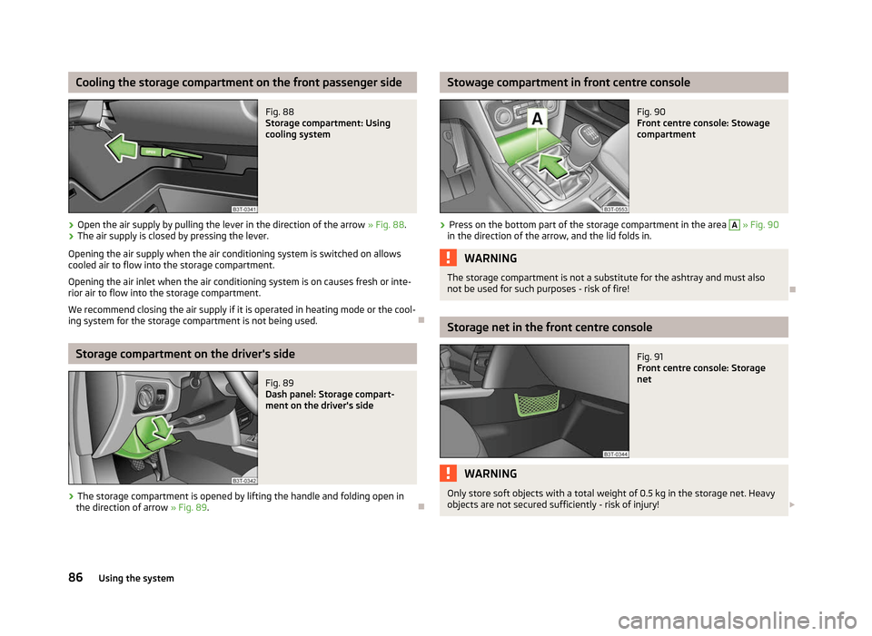
Cooling the storage compartment on the front passenger side
Fig. 88
Storage compartment: Using
cooling system
› Open the air supply by pulling the lever in the direction of the arrow
» Fig. 88.
› The air supply is closed by pressing the lever.
Opening the air supply when the air conditioning system is switched on allows
cooled air to flow into the storage compartment.
Opening the air inlet when the air conditioning system is on causes fresh or inte-
rior air to flow into the storage compartment.
We recommend closing the air supply if it is operated in heating mode or the cool-
ing system for the storage compartment is not being used. ÐStorage compartment on the driver's side
Fig. 89
Dash panel: Storage compart-
ment on the driver's side
› The storage compartment is opened by lifting the handle and folding open in
the direction of arrow » Fig. 89. Ð Stowage compartment in front centre console
Fig. 90
Front centre console: Stowage
compartment
› Press on the bottom part of the storage compartment in the area A
» Fig. 90
in the direction of the arrow, and the lid folds in. WARNING
The storage compartment is not a substitute for the ashtray and must also
not be used for such purposes - risk of fire! Ð Storage net in the front centre console
Fig. 91
Front centre console: Storage
net WARNING
Only store soft objects with a total weight of 0.5 kg in the storage net. Heavy
objects are not secured sufficiently - risk of injury! £
86 Using the system
Page 91 of 235

Stowage compartment in rear centre console
Fig. 98
Centre console at rear: Stowage
compartment
The storage compartment is equipped with a removable insert. › Open the storage compartment by pulling the handle A
» Fig. 98
in the direc-
tion of the arrow. WARNING
The storage compartment is not a substitute for the ashtray and must also
not be used for such purposes - risk of fire! ÐStowage compartment for an umbrella
Fig. 99
Left rear door: Stowage com-
partment for an umbrella
The storage compartment for an umbrella is located in the rear left door » Fig. 99. Note
An umbrella can be purchased from ŠKODA Original Accessories. Ð Seat backrest with through-loading channel
Fig. 100
Rear seats: Cover handle/boot: Unlock button
After folding the rear armrest and cover up, an opening in the seat backrest be-
comes visible through which the removable through-loading bag with skis can be
pushed. The armrest and cover can be folded forward from the passenger com-
partment or the boot.
Opening from the passenger compartment
› Fold down the rear armrest
» Fig. 62 on page 72.
› Pull the handle upwards to the stop and fold the cover down
» Fig. 100 - .
Opening from the boot
› Push the unlock button 1
» Fig. 100
- down and fold the cover (including the
armrest) forwards.
Closing
› Fold the cover and armrest upwards to the stop - the lid must click into place.
Ensure that the armrest is always locked into place after closing. This is apparent
as the red field above the unlocking button 1
is not visible from the boot.
WARNING
The through-loading channel is only intended for transporting skis that are
placed in a properly secured, removable through-loading bag » page 90.Ð
89
Seats and Stowage