ESP SKODA SUPERB 2012 2.G / (B6/3T) Owner's Manual
[x] Cancel search | Manufacturer: SKODA, Model Year: 2012, Model line: SUPERB, Model: SKODA SUPERB 2012 2.G / (B6/3T)Pages: 235, PDF Size: 5.86 MB
Page 13 of 235
CAUTION
We recommend that you do not reset the Service Interval Display yourself as this
can result in the incorrect setting of the Service Interval Display, which can also
cause possible problems with the operation of your vehicle. Note
■ Never reset the display between service intervals, as this will result in the incor-
rect display. ■ Information is retained in the Service Interval Display even after the vehicle bat-
tery is disconnected.
■ If the instrument cluster is exchanged after a repair, the correct values must be
entered in the counter for the Service Interval Display. This work is carried out by
a ŠKODA specialist garage. ■ After resetting the display with flexible service intervals, the displayed data is
the same as that for a vehicle with fixed service intervals. We therefore recom-
mend that the Service Interval Display is only reset by a
ŠKODA Service Partner,
who will reset the display with a vehicle system tester. ■ For more information on the service intervals » Service Plan. ÐDigital clock
First read and observe the introductory information and safety warn-
ings on page 8.
The clock is set with the buttons 3
and 7
» Fig. 2 on page 8.
Select the display that you wish to change with the button 3
and carry out the
change with the button 7
.
On vehicles that are fitted with the information display, it is also possible to set
the clock in the menu Time » page 16. Ð
ä Recommended gear
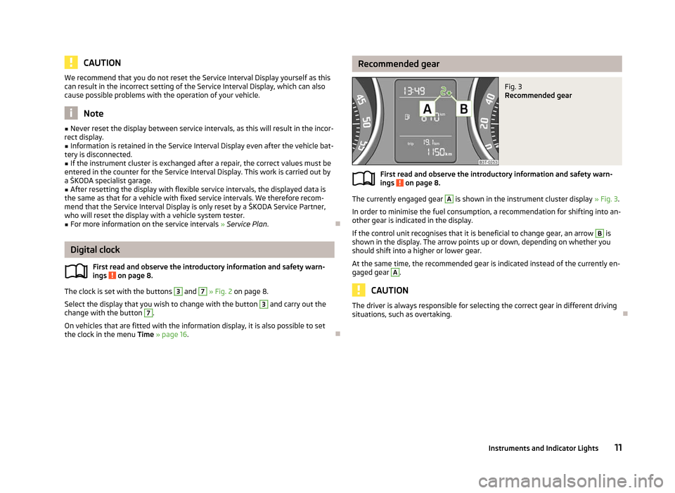
Fig. 3
Recommended gear
First read and observe the introductory information and safety warn-
ings on page 8.
The currently engaged gear A
is shown in the instrument cluster display
» Fig. 3.
In order to minimise the fuel consumption, a recommendation for shifting into an-
other gear is indicated in the display.
If the control unit recognises that it is beneficial to change gear, an arrow B
is
shown in the display. The arrow points up or down, depending on whether you
should shift into a higher or lower gear.
At the same time, the recommended gear is indicated instead of the currently en-
gaged gear A
.
CAUTION
The driver is always responsible for selecting the correct gear in different driving
situations, such as overtaking. Ð
ä
11
Instruments and Indicator Lights
Page 18 of 235

Main menu
Fig. 7
Information display: Control elements on the windscreen wiper lever/
control elements on the multifunction steering wheel
First read and observe the introductory information and safety warn-
ings on page 15.
Operating with the buttons on the windscreen wiper lever
›
Activate the Main menu
by pressing the rocker switch A
» Fig. 7 for longer.
› Individual menu items can be selected by means of the rocker switch A
. When
the pushbutton B
is briefly pressed, the information you have selected is dis-
played.
Operating with the buttons on the multifunction steering wheel
› Activate the Main menu
by pressing and holding the button C
» Fig. 7
for a
short while.
› By briefly pressing the C
button you will reach one level higher.
› The individual menus can be selected by pressing the adjustment wheel D
.
The selected menu is displayed after briefly pressing the adjustment wheel D
.
You can select the following information:
■ MFD »
page 12
■ Audio » Operating instructions for the radio
■ Navigation » Operating instructions for the navigation system
■ Phone » page 126
■ Aux. Heating » page 100
■ Assistants » page 119
■ Vehicle status » page 18
■ Settings » page 16
ä
The menu items
Audio and Navigation are only displayed when the factory-fitted
radio or navigation system is switched on.
The menu item Aux. heating is only displayed if a factory-fitted auxiliary heating
is installed.
The menu item Assistants is only then displayed if the vehicle is fitted with fati-
gue detection. Note
If the information display is not activated at that moment, the menu always shifts
to one of the higher levels after approx. 10
seconds.Ð Settings
First read and observe the introductory information and safety warn-
ings on page 15.
You can change certain settings by means of the information display. The current
setting is shown on the information display in the respective menu at the top be-
low the line.
You can select the following information:
■ Language
■ Autom. blind
■ MFD data
■ Convenience
■ Lights & Vision
■ Time
■ Winter tyres
■ Units
■ Assistants
■ Alternative speed displayed
■ Service
■ Factory setting
■ Back
Select the menu item Back to return to one level higher in the menu.
Language
You can set the language for the warning and information texts here. £
ä
16 Using the system
Page 21 of 235
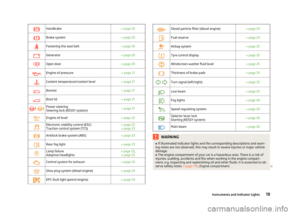
Handbrake
» page 20
Brake system
» page 20
Fastening the seat belt
» page 20
Generator
» page 20
Open door
» page 20
Engine oil pressure
» page 21
Coolant temperature/coolant level
» page 21
Bonnet
» page 21
Boot lid
» page 21
Power steering
Steering lock (KESSY system)
» page 21
Engine oil level
» page 22
Electronic stability control (ESC)
Traction control system (TCS) » page 22
» page 23
Antilock brake system (ABS)
» page 23
Rear fog light
» page 23
Lamp failure
Adaptive headlights » page 23
,
» page 23
Control system for exhaust
» page 23
Glow plug system (diesel engine)
» page 24
EPC fault light (petrol engine)
» page 24
Diesel particle filter (diesel engine)
» page 24
Fuel reserve
» page 24
Airbag system
» page 25
Tyre control display
» page 25
Windscreen washer fluid level
» page 25
Thickness of brake pads
» page 25
Turn signal (left/right).
» page 25
Low beam
» page 25
Fog lights
» page 26
Speed regulating system
» page 26
Selector lever lock
Starting (KESSY system)
» page 26
Main beam
» page 26 WARNING
■ If illuminated indicator lights and the corresponding descriptions and warn-
ing notes are not observed, this may result in severe injuries or major vehicle
damage.
■ The engine compartment of your car is a hazardous area. There is a risk of
injuries, scalding, accidents and fire when working in the engine compart-
ment, e.g. inspecting and replenishing oil and other fluids. It is essential to ob-
serve safety notes »
page 176, Engine compartment .Ð
19
Instruments and Indicator Lights
Page 34 of 235
Synchronisation
If the vehicle cannot be unlocked by actuating the remote control system then it
is possible that the code in the key and the control unit in the vehicle are no lon-
ger synchronised. This can occur when the buttons on the radio-operated key are
actuated a number of times outside of the operative range of the equipment or
the battery on the remote control was replaced.
This means it is necessary to synchronise the code as follows:
› press any button on the remote control key;
› pressing of the button means that the door will unlock with the key within 1 mi-
nute. ÐKESSY system
Introductory information
The KESSY system (Keyless Entry Start Exit System) enables a comfort unlocking
and locking of the vehicle and a start-up without actively using the remote con-
trol key. The KESSY system is integrated in the central locking system.
The safe securing system and anti-theft alarm system correspond to vehicles
without the KESSY system. Only the control elements are different.
When unlocking and locking the vehicle or for starting the engine it suffices to
carry the key with you, e.g. in your pocket. ÐLocking/unlocking
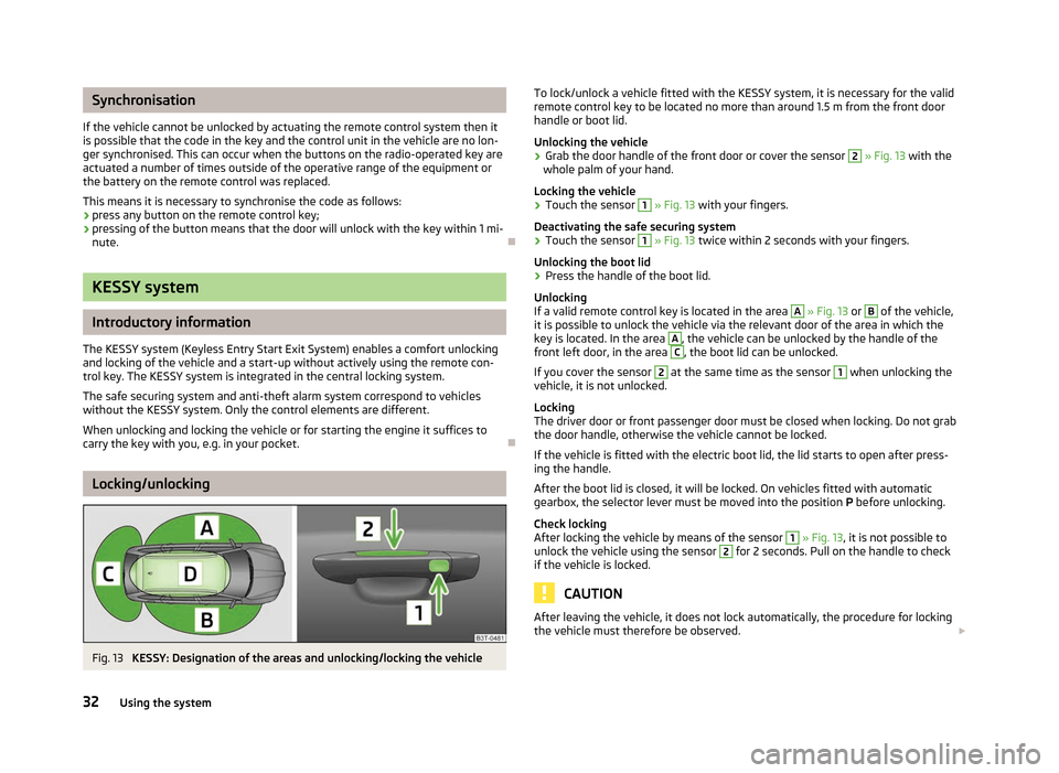
Fig. 13
KESSY: Designation of the areas and unlocking/locking the vehicle To lock/unlock a vehicle fitted with the KESSY system, it is necessary for the valid
remote control key to be located no more than around 1.5
m from the front door
handle or boot lid.
Unlocking the vehicle
› Grab the door handle of the front door or cover the sensor 2
» Fig. 13 with the
whole palm of your hand.
Locking the vehicle
› Touch the sensor 1
» Fig. 13 with your fingers.
Deactivating the safe securing system
› Touch the sensor 1
» Fig. 13 twice within 2
seconds with your fingers.
Unlocking the boot lid
› Press the handle of the boot lid.
Unlocking
If a valid remote control key is located in the area A
» Fig. 13 or B
of the vehicle,
it is possible to unlock the vehicle via the relevant door of the area in which the
key is located. In the area A
, the vehicle can be unlocked by the handle of the
front left door, in the area C
, the boot lid can be unlocked.
If you cover the sensor 2
at the same time as the sensor 1
when unlocking the
vehicle, it is not unlocked.
Locking
The driver door or front passenger door must be closed when locking. Do not grab
the door handle, otherwise the vehicle cannot be locked.
If the vehicle is fitted with the electric boot lid, the lid starts to open after press-
ing the handle.
After the boot lid is closed, it will be locked. On vehicles fitted with automatic
gearbox, the selector lever must be moved into the position P before unlocking.
Check locking
After locking the vehicle by means of the sensor 1
»
Fig. 13, it is not possible to
unlock the vehicle using the sensor 2
for 2 seconds. Pull on the handle to check
if the vehicle is locked. CAUTION
After leaving the vehicle, it does not lock automatically, the procedure for locking
the vehicle must therefore be observed. £
32 Using the system
Page 43 of 235
CAUTION
■ Keep the windows clean to ensure the correct functionality of the electric win-
dows. ■ In the event that the windows are frozen, first of all eliminate the
ice » page 170 , De-icing windows and exterior mirrors and only then operate the
power windows otherwise the power window mechanism could be damaged. ■ When leaving the locked vehicle make sure that the windows are closed at all
times. Note
■ After switching the ignition off, it is still possible to open or close the windows
for approx. 10
minutes. The power windows are only switched off completely
once the driver or front passenger door are opened. ■ When driving always use the existing heating, air conditioning and ventilation
system for ventilating the interior of the vehicle. If the windows are opened, dust
as well as other dirt can get into the vehicle and in addition the wind noise is
more at certain speeds.
■ At high speeds, you should keep the windows closed to prevent unnecessarily
high fuel consumption.
■ The convenience opening of the windows by means of the key in the driver's
lock is only possible within 45
seconds of deactivating or activating the alarm sys-
tem. ÐWindow open/close
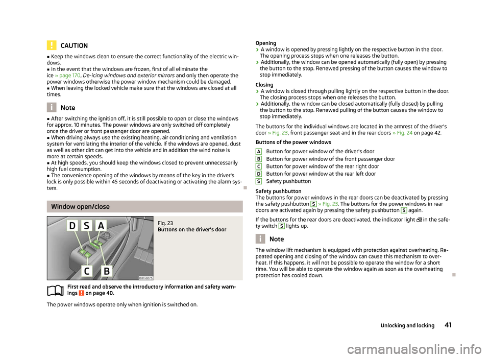
Fig. 23
Buttons on the driver's door
First read and observe the introductory information and safety warn-
ings on page 40.
The power windows operate only when ignition is switched on.
ä Opening
› A window is opened by pressing lightly on the respective button in the door.
The opening process stops when one releases the button.
› Additionally, the window can be opened automatically (fully open) by pressing
the button to the stop. Renewed pressing of the button causes the window to
stop immediately.
Closing
› A window is closed through pulling lightly on the respective button in the door.
The closing process stops when one releases the button.
› Additionally, the window can be closed automatically (fully closed) by pulling
the button to the stop. Renewed pulling of the button causes the window to
stop immediately.
The buttons for the individual windows are located in the armrest of the driver's
door » Fig. 23, front passenger seat and in the rear doors »
Fig. 24 on page 42.
Buttons of the power windows Button for power window of the driver's door
Button for power window of the front passenger door
Button for power window of the rear right door
Button for power window at the rear left door
Safety pushbutton
Safety pushbutton
The buttons for power windows in the rear doors can be deactivated by pressing
the safety pushbutton S
» Fig. 23. The buttons for the power windows in rear
doors are activated again by pressing the safety pushbutton S
again.
If the buttons for the rear doors are deactivated, the indicator light in the safe-
ty switch S
lights up.
Note
The window lift mechanism is equipped with protection against overheating. Re-
peated opening and closing of the window can cause this mechanism to over-
heat. If this happens, it will not be possible to operate the window for a short
time. You will be able to operate the window again as soon as the overheating
protection has cooled down. Ð A
B
C
D
S
41
Unlocking and locking
Page 44 of 235

Window in the front passenger door and the rear doors open/
close
Fig. 24
Arrangement of the button on
the rear door
First read and observe the introductory information and safety warn-
ings on page 40.
There is a button in the front passenger door and in the rear doors for that win-
dow.
Opening
› A window is opened by pressing lightly on the respective button in the door.
The opening process stops when one releases the button.
› Additionally, the window can be opened automatically (fully open) by pressing
the button to the stop. Renewed pressing of the button causes the window to
stop immediately.
Closing
› A window is closed through pulling lightly on the respective button in the door.
The closing process stops when one releases the button.
› Additionally, the window can be closed automatically (fully closed) by pulling
the button to the stop. Renewed pulling of the button causes the window to
stop immediately. ÐForce limiter of the power windows
First read and observe the introductory information and safety warn-
ings on page 40.
The electrically operated power windows are fitted with a force limiter. It reduces
the risk of bruises or injuries when closing the windows.
ä
ä If there is an obstacle, the closing process is stopped and the window goes down
by several centimetres.
If the obstacle prevents the window from being closed during the next 10 sec-
onds, the closing process is interrupted once again and the window goes down by
several centimetres.
If you attempt to close the window again within 10
seconds of the window being
moved down for the second time, even though the obstacle was not yet been re-
moved, the closing process is only stopped. During this time it is not possible to
automatically close the window. The force limiter is still switched on.
The force limiter is only switched off if you attempt to close the window again
within the next 10 seconds - the window will now close with full force!
If you wait longer than 10 seconds, the force limiter is switched on again. Ð Window convenience operation
First read and observe the introductory information and safety warn-
ings on page 40.
The electrically powered windows can be opened and closed as follows when un-
locking and locking the vehicle.
Opening
›
Press and hold the unlock button
on the remote control key.
› Press and hold the upper part of the central locking button in the driver's door.
Closing
› Press and hold the lock button
on the remote control key.
› Press and hold the lower part of the central locking button in the driver's door.
› Hold the key in the driver's lock in the lock position.
› With the KESSY system, cover the sensor 2
» Fig. 13 on page 32
.
You can interrupt the opening or closing process for the windows immediately by
releasing the key or the lock button. Ð
ä
42 Using the system
Page 50 of 235

Lights and visibility
Lights
ä
Introduction
This chapter contains information on the following subjects:
Switching lights on and off 49
DAY LIGHT function (Daylight driving light) 49
Automatic driving lamp control 49
Parking light 50
COMING HOME/LEAVING HOME function 50
Adaptive headlights (AHL) 51
Fog lights 52
Fog lights with the function CORNER 52
Rear fog lights 52
Instrument lighting 53
Headlight beam adjustment 53
Switches for the hazard warning light system 53
Turn signal and main beam lever 54
On models fitted with right-hand steering the position of certain switches differs
from that shown in » Fig. 30 on page
49. The symbols which mark the switch
positions are identical, however.
The low beam continues to shine while the ignition is switched on and the light
switch is in the position or . After switching off the ignition, the low beam
is switched off automatically and only the side lights come on. The side lights also
go out after the ignition key is removed. WARNING
■ Never drive with only the side lights on! The side lights are not bright
enough to light up the road sufficiently in front of you or to be seen by other
oncoming traffic. Therefore always switch on the low beam when it is dark or
if visibility is poor.
■ The automatic driving lamp control
only operates as a support and does
not release the driver from his responsibility to check the light and, if necessa-
ry, to switch on the light depending on the light conditions. The light sensor
cannot, for example, detect rain or snow. Under these conditions we recom-
mend switching on the low beam or fog lights! CAUTION
■ The activation of the lights should only be undertaken in accordance with na-
tional legal requirements.
■ The driver is always responsible for the correct settings and use of the lights. Note
■ If the light switch is in the position , the ignition key is removed and the driv-
er's door is open, an audible warning signal will sound. The audible warning signal
is switched off by means of the door contact when the driver's door is closed (ig-
nition off), however, the side lights remain on to illuminate the parked vehicle if
necessary. ■ If there is a fault in the light switch, the low beam comes on automatically.
■ In the event of cool or humid weather conditions, the headlights can be misted
up from inside. The temperature difference between interior and external area of
the headlight lenses is decisive. When the driving lights are switched on, the light
outlet surfaces are free from mist after a short period, although the headlight
lenses may still be misted up in the peripheral areas. It also concerns reverse light
and turn signal lights. This mist has no influence on the life of the lighting system. Ð
48 Using the system
Page 55 of 235
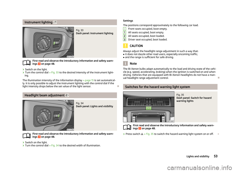
Instrument lighting
Fig. 33
Dash panel: Instrument lighting
First read and observe the introductory information and safety warn-
ings on page 48.
›
Switch on the light.
› Turn the control dial
» Fig. 33 to the desired intensity of the instrument light-
ing.
The illumination intensity of the Information display »
page 15 is set automatical-
ly. It is only possible to adjust the instrument lighting with the control dial if the
light intensity drops below the set value of the light sensor. ÐHeadlight beam adjustment
Fig. 34
Dash panel: Lights and visibility
First read and observe the introductory information and safety warn-
ings on page 48.
›
Switch on the light.
› Turn the control dial
» Fig. 34 to the desired width of illumination.
ä
ä Settings
The positions correspond approximately to the following car load.
Front seats occupied, boot empty.
All seats occupied, boot empty.
All seats occupied, boot loaded.
Driver seat occupied, boot loaded. CAUTION
Always adjust the headlight range adjustment in such a way that:
■ it does not dazzle other road users, especially oncoming traffic;
■ and the range is sufficient for safe driving. Note
The Bi-Xenon bulbs adapt automatically to the load and driving state of the vehi-
cle (e.g. speed, accelerating, braking) when the ignition is switched on and when
driving. Vehicles that are equipped with Bi-Xenon headlights do not have a man-
ual headlight range adjustment control. Ð Switches for the hazard warning light system
Fig. 35
Dash panel: Switch for hazard
warning lights
First read and observe the introductory information and safety warn-
ings on page 48.
›
Press switch
» Fig. 35 to switch the hazard warning light system on or off. £ -
1
2
3
ä
53
Lights and visibility
Page 56 of 235
All the turn signal lights on the vehicle flash at the same time when the hazard
warning light system is switched on. The indicator light for the turn signals and
the indicator light in the switch also flash at the same time. The hazard warning
light system can also be operated if the ignition is switched off.
The hazard warning light system is switched on automatically if an airbag is de-
ployed in the event of an accident.
Note
The hazard warning light system must be switched on if, for example:
■ you encounter a traffic congestion;
■ your vehicle breaks down or an emergency situation occurs. ÐTurn signal and main beam lever
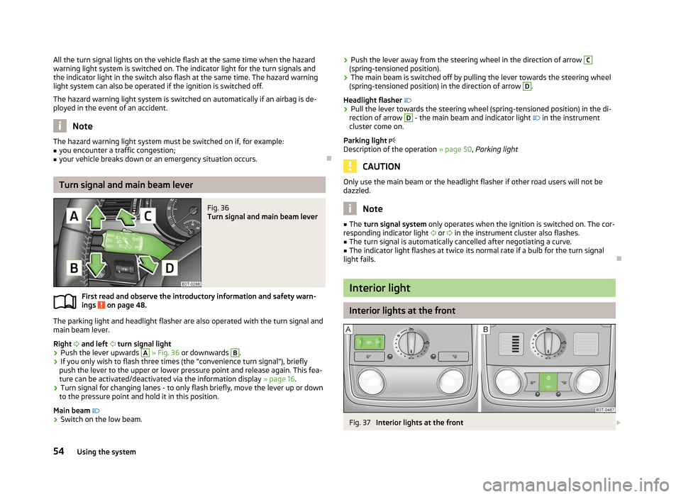
Fig. 36
Turn signal and main beam lever
First read and observe the introductory information and safety warn-
ings on page 48.
The parking light and headlight flasher are also operated with the turn signal and
main beam lever.
Right and left turn signal light
› Push the lever upwards A
» Fig. 36
or downwards B
.
› If you only wish to flash three times (the "convenience turn signal"), briefly
push the lever to the upper or lower pressure point and release again. This fea-
ture can be activated/deactivated via the information display » page 16.
› Turn signal for changing lanes - to only flash briefly, move the lever up or down
to the pressure point and hold it in this position.
Main beam
› Switch on the low beam.
ä ›
Push the lever away from the steering wheel in the direction of arrow C
(spring-tensioned position).
› The main beam is switched off by pulling the lever towards the steering wheel
(spring-tensioned position) in the direction of arrow D
.
Headlight flasher
› Pull the lever towards the steering wheel (spring-tensioned position) in the di-
rection of arrow D
- the main beam and indicator light
in the instrument
cluster come on.
Parking light
Description of the operation » page 50, Parking light CAUTION
Only use the main beam or the headlight flasher if other road users will not be
dazzled. Note
■ The turn signal system only operates when the ignition is switched on. The cor-
responding indicator light or
in the instrument cluster also flashes.
■ The turn signal is automatically cancelled after negotiating a curve.
■ The indicator light flashes at twice its normal rate if a bulb for the turn signal
light fails. Ð Interior light
Interior lights at the front
Fig. 37
Interior lights at the front £
54 Using the system
Page 62 of 235
The rain sensor automatically regulates the break between the individual wiper
strokes depending on the intensity of the rain.
The rear window is wiped once if the windscreen wipers are on when reverse
gear is selected.
After the windscreen wiper switches off each time or the ignition switches off for
the third time, the position of the windscreen wiper changes, this counteracts an
early fatigue of the wiper rubbers.
Top up with windscreen wiper fluid
» page 182.WARNING
■ Properly maintained windscreen wiper blades are essential for clear visibility
and safe driving » page 62.
■ Do not use the windscreen washer system at low temperatures, without
heating the windscreen beforehand. Otherwise the window cleaner could
freeze on the windscreen and restrict the view to the front.
■ The rain sensor only operates as a support. The driver is not released from
the responsibility to set the function of the windscreen wipers manually de-
pending on the visibility conditions. CAUTION
■ In cold temperatures and during the winter, check before the journey or before
switching on the ignition that the wiper blades are not frozen to the windscreen.
If the windscreen wipers are switched on when the blades are frozen to the
windscreen, this may damage both the blades and windscreen wiper motor!
■ If the ignition is switched off while the windscreen wipers are switched on, the
windscreen wipers will continue wiping in the same mode after the ignition is
turned back on. The windscreen wipers could freeze up in cold temperatures be-
tween the time the ignition was turned off and when it was turned back on again.
■ Carefully detach frozen wiper blades from the front or rear window.
■ Remove snow and ice from the windscreen wipers before driving.
■ If the windscreen wipers are handled carelessly, there is a risk of damage to the
windscreen.
■ Replace the windscreen wiper blades once or twice a year for safety reasons.
These can be purchased from a ŠKODA Service Partner.
■ The ignition must not be switched on if the front windscreen wiper arms are fol-
ded out. The wiper blades would move back into their rest position and while do-
ing so damage the paintwork of the bonnet. Note
■ If the slower 2
» Fig. 47 on page 60 or the faster 3
wiper setting is switched
on and the vehicle speed decreases to below 4 km/h, the lower wiper step is
switched on automatically. At a speed increase of more than 8 km/h the previous
wiper setting is established again.
■ If there is an obstacle on the windscreen, the wiper will try to push away the
obstacle. If the obstacle continues to block the wiper, the wiper stops automati-
cally after 5 attempts to eliminate the obstacle, in order to avoid a damage to the
wiper. Remove the the obstacle and switch the wiper on again. ■ The windscreen washer nozzles for the windscreen are heated when the en-
gine is running and the outside temperature is less than approx. +10
°C.
■ The content of the windscreen washer fluid reservoir is 3 litres. On vehicles fit-
ted with the headlight cleaning system, the volume is 5.5
litres. On vehicles fitted
with auxiliary heating, the content of the windscreen wiper reservoir is 4.5 litres.
■ The wiper blades should be cleaned on a regular basis with a windscreen clean-
er to avoid any smears. The wiper blades should be cleaned with a sponge or
cloth if they are heavily soiled by insect residues, for example. Ð Activating the windscreen wipers and washers
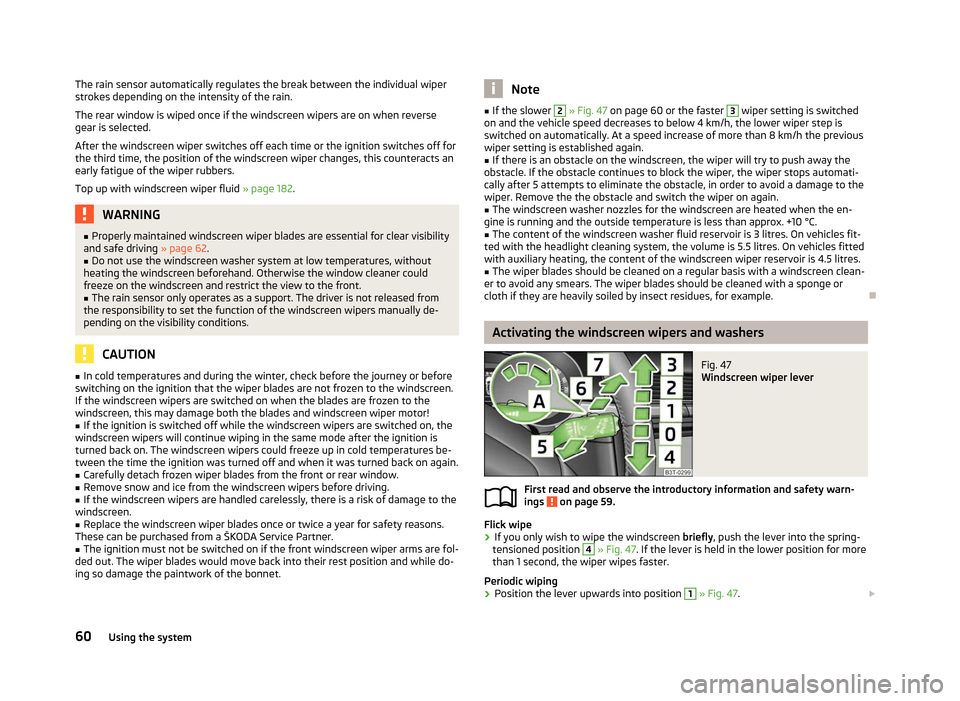
Fig. 47
Windscreen wiper lever
First read and observe the introductory information and safety warn-
ings on page 59.
Flick wipe
› If you only wish to wipe the windscreen
briefly, push the lever into the spring-
tensioned position 4
» Fig. 47. If the lever is held in the lower position for more
than 1 second, the wiper wipes faster.
Periodic wiping
› Position the lever upwards into position 1
» Fig. 47.
£
ä
60 Using the system