buttons SKODA SUPERB 2012 2.G / (B6/3T) Owner's Manual
[x] Cancel search | Manufacturer: SKODA, Model Year: 2012, Model line: SUPERB, Model: SKODA SUPERB 2012 2.G / (B6/3T)Pages: 235, PDF Size: 5.86 MB
Page 9 of 235
Using the system
Cockpit
Overview
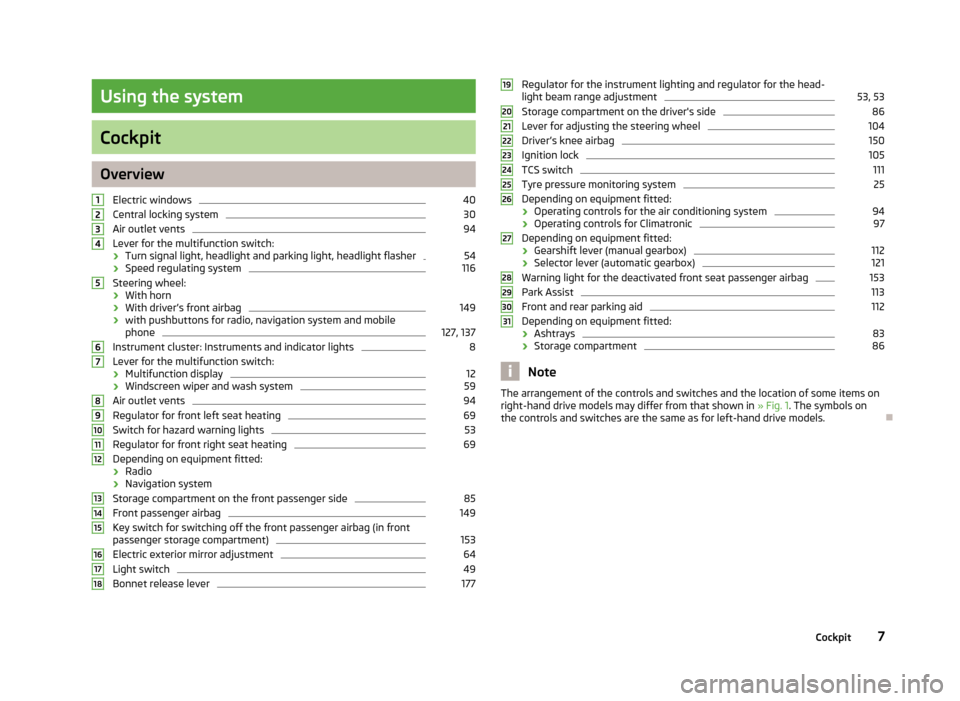
Electric windows 40
Central locking system 30
Air outlet vents 94
Lever for the multifunction switch:
› Turn signal light, headlight and parking light, headlight flasher 54
› Speed regulating system 116
Steering wheel:
› With horn
› With driver’s front airbag 149
› with pushbuttons for radio, navigation system and mobile
phone 127, 137
Instrument cluster: Instruments and indicator lights 8
Lever for the multifunction switch:
› Multifunction display 12
› Windscreen wiper and wash system 59
Air outlet vents 94
Regulator for front left seat heating 69
Switch for hazard warning lights 53
Regulator for front right seat heating 69
Depending on equipment fitted:
› Radio
› Navigation system
Storage compartment on the front passenger side 85
Front passenger airbag 149
Key switch for switching off the front passenger airbag (in front
passenger storage compartment) 153
Electric exterior mirror adjustment 64
Light switch 49
Bonnet release lever 1771
2
3
4
5
6
7
8
9
10
11
12
13
14
15
16
17
18 Regulator for the instrument lighting and regulator for the head-
light beam range adjustment 53, 53
Storage compartment on the driver's side 86
Lever for adjusting the steering wheel 104
Driver’s knee airbag 150
Ignition lock 105
TCS switch 111
Tyre pressure monitoring system 25
Depending on equipment fitted:
› Operating controls for the air conditioning system 94
› Operating controls for Climatronic 97
Depending on equipment fitted:
› Gearshift lever (manual gearbox) 112
› Selector lever (automatic gearbox) 121
Warning light for the deactivated front seat passenger airbag 153
Park Assist 113
Front and rear parking aid 112
Depending on equipment fitted:
› Ashtrays 83
› Storage compartment 86
Note
The arrangement of the controls and switches and the location of some items on
right-hand drive models may differ from that shown in »
Fig. 1. The symbols on
the controls and switches are the same as for left-hand drive models. Ð 19
20
21
22
23
24
25
26
27
28
29
30
31
7
Cockpit
Page 13 of 235
CAUTION
We recommend that you do not reset the Service Interval Display yourself as this
can result in the incorrect setting of the Service Interval Display, which can also
cause possible problems with the operation of your vehicle. Note
■ Never reset the display between service intervals, as this will result in the incor-
rect display. ■ Information is retained in the Service Interval Display even after the vehicle bat-
tery is disconnected.
■ If the instrument cluster is exchanged after a repair, the correct values must be
entered in the counter for the Service Interval Display. This work is carried out by
a ŠKODA specialist garage. ■ After resetting the display with flexible service intervals, the displayed data is
the same as that for a vehicle with fixed service intervals. We therefore recom-
mend that the Service Interval Display is only reset by a
ŠKODA Service Partner,
who will reset the display with a vehicle system tester. ■ For more information on the service intervals » Service Plan. ÐDigital clock
First read and observe the introductory information and safety warn-
ings on page 8.
The clock is set with the buttons 3
and 7
» Fig. 2 on page 8.
Select the display that you wish to change with the button 3
and carry out the
change with the button 7
.
On vehicles that are fitted with the information display, it is also possible to set
the clock in the menu Time » page 16. Ð
ä Recommended gear
Fig. 3
Recommended gear
First read and observe the introductory information and safety warn-
ings on page 8.
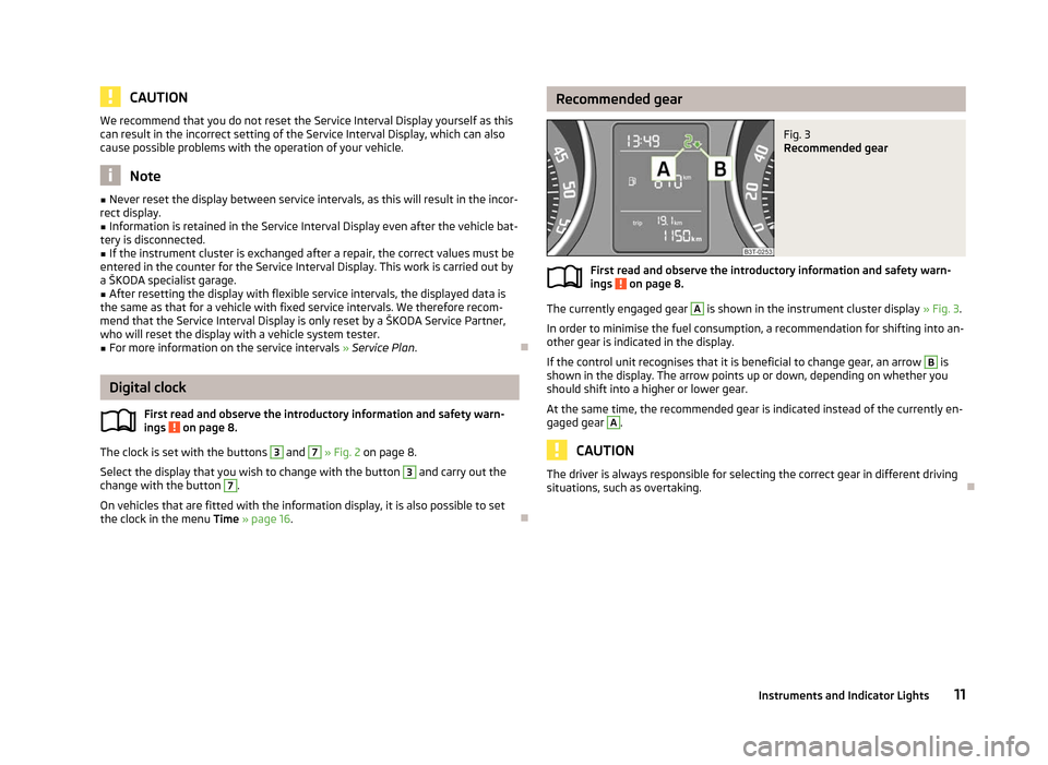
The currently engaged gear A
is shown in the instrument cluster display
» Fig. 3.
In order to minimise the fuel consumption, a recommendation for shifting into an-
other gear is indicated in the display.
If the control unit recognises that it is beneficial to change gear, an arrow B
is
shown in the display. The arrow points up or down, depending on whether you
should shift into a higher or lower gear.
At the same time, the recommended gear is indicated instead of the currently en-
gaged gear A
.
CAUTION
The driver is always responsible for selecting the correct gear in different driving
situations, such as overtaking. Ð
ä
11
Instruments and Indicator Lights
Page 18 of 235

Main menu
Fig. 7
Information display: Control elements on the windscreen wiper lever/
control elements on the multifunction steering wheel
First read and observe the introductory information and safety warn-
ings on page 15.
Operating with the buttons on the windscreen wiper lever
›
Activate the Main menu
by pressing the rocker switch A
» Fig. 7 for longer.
› Individual menu items can be selected by means of the rocker switch A
. When
the pushbutton B
is briefly pressed, the information you have selected is dis-
played.
Operating with the buttons on the multifunction steering wheel
› Activate the Main menu
by pressing and holding the button C
» Fig. 7
for a
short while.
› By briefly pressing the C
button you will reach one level higher.
› The individual menus can be selected by pressing the adjustment wheel D
.
The selected menu is displayed after briefly pressing the adjustment wheel D
.
You can select the following information:
■ MFD »
page 12
■ Audio » Operating instructions for the radio
■ Navigation » Operating instructions for the navigation system
■ Phone » page 126
■ Aux. Heating » page 100
■ Assistants » page 119
■ Vehicle status » page 18
■ Settings » page 16
ä
The menu items
Audio and Navigation are only displayed when the factory-fitted
radio or navigation system is switched on.
The menu item Aux. heating is only displayed if a factory-fitted auxiliary heating
is installed.
The menu item Assistants is only then displayed if the vehicle is fitted with fati-
gue detection. Note
If the information display is not activated at that moment, the menu always shifts
to one of the higher levels after approx. 10
seconds.Ð Settings
First read and observe the introductory information and safety warn-
ings on page 15.
You can change certain settings by means of the information display. The current
setting is shown on the information display in the respective menu at the top be-
low the line.
You can select the following information:
■ Language
■ Autom. blind
■ MFD data
■ Convenience
■ Lights & Vision
■ Time
■ Winter tyres
■ Units
■ Assistants
■ Alternative speed displayed
■ Service
■ Factory setting
■ Back
Select the menu item Back to return to one level higher in the menu.
Language
You can set the language for the warning and information texts here. £
ä
16 Using the system
Page 32 of 235

Vehicle locking/unlocking from the inside
Fig. 11
Central locking button
The doors and the boot lid can be unlocked/locked with the rocker switch on the
door opening lever of the driver or front passenger door » Fig. 11 even when the
ignition is not switched on.
The central locking button works only when the vehicle was not locked from the
outside and all doors are closed.
Locking
Press the symbol » Fig. 11 on the button. The symbol in the button comes on.
Unlocking
Press the symbol » Fig. 11 on the button. The symbol in the button is no longer
illuminated.
The following applies if your vehicle has been locked using the central locking
button.
› It is not possible to open the doors or the boot lid from the outside (safety fea-
ture, e.g. when stopping at traffic lights etc.).
› The vehicle doors can be unlocked and opened by pulling once on the door
opening lever.
› In the event of an accident in which the airbags are deployed, the locked doors
are automatically unlocked from the inside in order to enable rescuers to gain
access to the vehicle.
By pressing and holding down the symbol or on the rocker switch in the driv-
er's door, the windows can be conveniently closed or opened. WARNING
The central locking system also operates if the ignition is switched off. Chil-
dren should never be left unattended in the vehicle since it is difficult to pro-
vide assistance from the outside when the doors are locked. Locked doors
make it difficult for rescuers to get into the vehicle in an emergency - hazard! Note
If the safe securing system is activated » page 29, the door opening lever and the
central locking buttons do not operate. Ð Remote control
Introductory information
You can use the remote control key to:
› unlock and lock the vehicle,
› unlock or open the boot lid,
› open and close the windows
»
page 42, Window convenience operation .
The transmitter with the battery is housed in the handle of the remote control
key. The receiver is located in the interior of the vehicle. The operating range of
the remote control key is approx. 30 m. But this range of the remote control can
be reduced if the batteries are weak.
The key has a fold-open key bit which can be used for unlocking and locking the
car manually and also for starting the engine.
If a lost key is replaced or if the receiver unit has been repaired or replaced, the
system must be initialised by a ŠKODA Service Partner. Only then can the remote
control key be used again. Note
■ The remote control is automatically deactivated when the ignition is switched
on. ■ The operation of the remote control may temporarily be affected by interfer-
ence from transmitters close to the car and which operate in the same frequency
range (e.g. mobile phone, TV transmitter). £
30 Using the system
Page 34 of 235
Synchronisation
If the vehicle cannot be unlocked by actuating the remote control system then it
is possible that the code in the key and the control unit in the vehicle are no lon-
ger synchronised. This can occur when the buttons on the radio-operated key are
actuated a number of times outside of the operative range of the equipment or
the battery on the remote control was replaced.
This means it is necessary to synchronise the code as follows:
› press any button on the remote control key;
› pressing of the button means that the door will unlock with the key within 1 mi-
nute. ÐKESSY system
Introductory information
The KESSY system (Keyless Entry Start Exit System) enables a comfort unlocking
and locking of the vehicle and a start-up without actively using the remote con-
trol key. The KESSY system is integrated in the central locking system.
The safe securing system and anti-theft alarm system correspond to vehicles
without the KESSY system. Only the control elements are different.
When unlocking and locking the vehicle or for starting the engine it suffices to
carry the key with you, e.g. in your pocket. ÐLocking/unlocking
Fig. 13
KESSY: Designation of the areas and unlocking/locking the vehicle To lock/unlock a vehicle fitted with the KESSY system, it is necessary for the valid
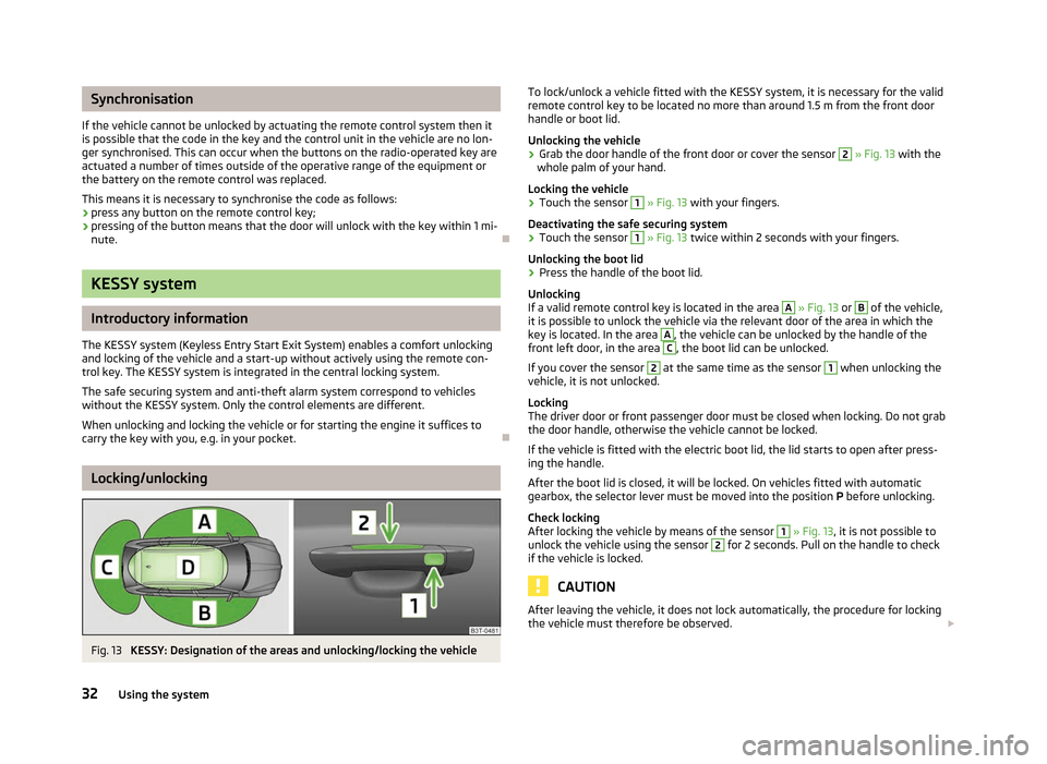
remote control key to be located no more than around 1.5
m from the front door
handle or boot lid.
Unlocking the vehicle
› Grab the door handle of the front door or cover the sensor 2
» Fig. 13 with the
whole palm of your hand.
Locking the vehicle
› Touch the sensor 1
» Fig. 13 with your fingers.
Deactivating the safe securing system
› Touch the sensor 1
» Fig. 13 twice within 2
seconds with your fingers.
Unlocking the boot lid
› Press the handle of the boot lid.
Unlocking
If a valid remote control key is located in the area A
» Fig. 13 or B
of the vehicle,
it is possible to unlock the vehicle via the relevant door of the area in which the
key is located. In the area A
, the vehicle can be unlocked by the handle of the
front left door, in the area C
, the boot lid can be unlocked.
If you cover the sensor 2
at the same time as the sensor 1
when unlocking the
vehicle, it is not unlocked.
Locking
The driver door or front passenger door must be closed when locking. Do not grab
the door handle, otherwise the vehicle cannot be locked.
If the vehicle is fitted with the electric boot lid, the lid starts to open after press-
ing the handle.
After the boot lid is closed, it will be locked. On vehicles fitted with automatic
gearbox, the selector lever must be moved into the position P before unlocking.
Check locking
After locking the vehicle by means of the sensor 1
»
Fig. 13, it is not possible to
unlock the vehicle using the sensor 2
for 2 seconds. Pull on the handle to check
if the vehicle is locked. CAUTION
After leaving the vehicle, it does not lock automatically, the procedure for locking
the vehicle must therefore be observed. £
32 Using the system
Page 43 of 235
CAUTION
■ Keep the windows clean to ensure the correct functionality of the electric win-
dows. ■ In the event that the windows are frozen, first of all eliminate the
ice » page 170 , De-icing windows and exterior mirrors and only then operate the
power windows otherwise the power window mechanism could be damaged. ■ When leaving the locked vehicle make sure that the windows are closed at all
times. Note
■ After switching the ignition off, it is still possible to open or close the windows
for approx. 10
minutes. The power windows are only switched off completely
once the driver or front passenger door are opened. ■ When driving always use the existing heating, air conditioning and ventilation
system for ventilating the interior of the vehicle. If the windows are opened, dust
as well as other dirt can get into the vehicle and in addition the wind noise is
more at certain speeds.
■ At high speeds, you should keep the windows closed to prevent unnecessarily
high fuel consumption.
■ The convenience opening of the windows by means of the key in the driver's
lock is only possible within 45
seconds of deactivating or activating the alarm sys-
tem. ÐWindow open/close
Fig. 23
Buttons on the driver's door
First read and observe the introductory information and safety warn-
ings on page 40.
The power windows operate only when ignition is switched on.
ä Opening
› A window is opened by pressing lightly on the respective button in the door.
The opening process stops when one releases the button.
› Additionally, the window can be opened automatically (fully open) by pressing
the button to the stop. Renewed pressing of the button causes the window to
stop immediately.
Closing
› A window is closed through pulling lightly on the respective button in the door.
The closing process stops when one releases the button.
› Additionally, the window can be closed automatically (fully closed) by pulling
the button to the stop. Renewed pulling of the button causes the window to
stop immediately.
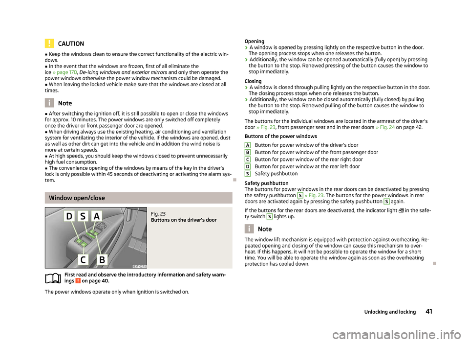
The buttons for the individual windows are located in the armrest of the driver's
door » Fig. 23, front passenger seat and in the rear doors »
Fig. 24 on page 42.
Buttons of the power windows Button for power window of the driver's door
Button for power window of the front passenger door
Button for power window of the rear right door
Button for power window at the rear left door
Safety pushbutton
Safety pushbutton
The buttons for power windows in the rear doors can be deactivated by pressing
the safety pushbutton S
» Fig. 23. The buttons for the power windows in rear
doors are activated again by pressing the safety pushbutton S
again.
If the buttons for the rear doors are deactivated, the indicator light in the safe-
ty switch S
lights up.
Note
The window lift mechanism is equipped with protection against overheating. Re-
peated opening and closing of the window can cause this mechanism to over-
heat. If this happens, it will not be possible to operate the window for a short
time. You will be able to operate the window again as soon as the overheating
protection has cooled down. Ð A
B
C
D
S
41
Unlocking and locking
Page 47 of 235
Panoramic sliding roof (Combi)
Introductory information
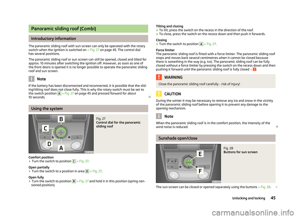
The panoramic sliding roof with sun screen can only be operated with the rotary
switch when the ignition is switched on » Fig. 27 on page
45. The control dial
has several positions.
The panoramic sliding roof or sun screen can still be opened, closed and tilted for
approx. 10 minutes after switching the ignition off. However, as soon as one of
the front doors is opened it is no longer possible to operate the panoramic sliding
roof and sun screen. Note
If the battery has been disconnected and reconnected, it is possible that the slid-
ing/tilting roof does not close fully. This is why the rotary switch must be set to
the switch position A
» Fig. 27
on page 45 and pressed forward for about
10 seconds. ÐUsing the system
Fig. 27
Control dial for the panoramic
sliding roof
Comfort position
› Turn the switch to position C
» Fig. 27.
Open partially
› Turn the switch to a position in area D
» Fig. 27
.
Open fully
› Turn the switch to position B
» Fig. 27 and hold it in this position (spring-ten-
sioned position). Tilting and closing
› To tilt, press the switch on the recess in the direction of the roof.
› To close, press the switch on the recess down and then push it forwards.
Closing
› Turn the switch to position A
» Fig. 27.
Force limiter
The panoramic sliding roof is fitted with a force limiter. The panoramic sliding roof
stops and moves back several centimetres when it cannot be closed because
there is something in the way (e.g. ice). The panoramic sliding roof can be fully
closed without a force limiter by pressing the switch on the recess down and then
pushing it forward until the panoramic sliding roof is fully closed » .
WARNING
Close the panoramic sliding roof carefully - risk of injury! CAUTION
During the winter it may be necessary to remove any ice and snow in the vicinity
of the panoramic sliding roof before opening it to prevent any damage to the
opening mechanism. Note
When the panoramic sliding roof is in the comfort position, the intensity of the
wind noise is reduced. Ð Sunshade open/close
Fig. 28
Buttons for sun screen
The sun screen can be closed or opened separately using the buttons » Fig. 28.£
45
Unlocking and locking
Page 70 of 235
Memory function of the power seat
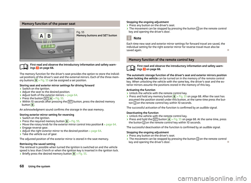
Fig. 55
Memory buttons and SET button
First read and observe the introductory information and safety warn-
ings on page 66.
The memory function for the driver's seat provides the option to store the individ-
ual positions of the driver's seat and the external mirrors. Each of the three mem-
ory buttons B
» Fig. 55 can be assigned a set position.
Storing seat and exterior mirror settings for driving forward
› Switch on the ignition.
› Adjust the seat to the desired position.
› Adjust both of the exterior mirrors
» page 64.
› Press the button
SET A
» Fig. 55.
› Within 10 seconds after pressing the
SET button, press the desired memory
button B
.
An acknowledgment sound confirms the storage in the seat memory.
Storing exterior mirror setting for reversing
› Switch on the ignition.
› Press the required memory button B
» Fig. 55.
› Move the rotary knob for the exterior mirror control into position
» page 64 .
› Engage reverse gear.
› Adjust the right exterior mirror to the desired position
» page 64.
› Take the vehicle out of gear.
The adjusted position of the exterior mirror is stored in the seat memory.
Retrieving the saved setting
The retrieval is possible when turned the ignition is switched on and the vehicle
speed is less than 5
km/h or when the ignition key is inserted in the ignition lock.
› Briefly press the desired memory button B
» Fig. 55.
ä
Stopping the ongoing adjustment
› Press any button on the driver's seat.
› The movement can be stopped by pressing the button
on the remote control
key and opening the driver's door. Note
Each time new seat and exterior mirror settings for forward travel are saved, the
individual setting for the right exterior mirror for reverse travel must also be
saved again. Ð Memory function of the remote control key
First read and observe the introductory information and safety warn-
ings on page 66.
The automatic storage function of the driver's seat and exterior mirrors position
when locking the vehicle
can be turned on in the memory of the remote control
key. When unlocking the vehicle with the same key, the driver's seat and the ex-
terior mirrors assume the positions stored in the memory of this key.
Activating the function
› Unlock the vehicle with the remote control key.
› Press and hold any memory button B
» Fig. 55 on page 68
. After the seat has
assumed the position stored under this button, at the same time press the but-
ton on the remote control key within 10 seconds.
The successful activation of the function is confirmed by an audible signal.
Deactivating the function
› Unlock the vehicle with the remote control key.
› Press and hold the
SET button A
» Fig. 55 on page 68
. At the same time, press
the button on the remote control key within 10 seconds.
The successful deactivation of the function is confirmed by an audible signal.
Stopping the ongoing adjustment
› Press any button on the driver's seat.
› The movement can be stopped by pressing the button
on the remote control
key and opening the driver's door. Ð
ä
68 Using the system
Page 80 of 235

The variable loading floor can be partially pulled out over the rear bumper. The
variable loading floor which is pulled out in such a way is solely used as a seat, for
example for changing shoes. When pulling out the variable loading floor, the front
edge (close to the rear seats) is lifted at the same time. Thus, small objects can no
longer fall into the space between the boot floor and the variable loading floor.
› Grasp the rear part of the variable loading floor by the handle, raise it slightly in
the direction of the arrow 1
» Fig. 72
and pull it out over the bumper in the di-
rection of the arrow 2
until it engages in the opening C
» Fig. 72.
› To push the variable loading floor back into place, grasp the part of the floor by
the handle, raise it slightly in the direction of the arrow 1
and push it forwards
up to the stop. CAUTION
Ensure that the raised front edge of the variable loading floor is not damaged. ÐDividing the boot with variable loading floor
Fig. 73
Dividing the boot
The boot can be divided with the variable loading floor.
› Grasp the rear part of the floor by the handle, raise it in direction of arrow 1
» Fig. 72 on page
77 and insert the rear edge in one of the openingsA
» Fig. 73
.
The variable loading floor is secured in the openings A
against movement.
The variable loading floor can be pulled out a little more before dividing the boot
with the variable loading floor » page 77 . This enlarges the space between the
rear seats and the separation. CAUTION
Ensure that the raised front edge of the variable loading floor is not damaged. Ð Removing and installing the variable loading floor
Fig. 74
Boot: Fold up variable loading floor Fig. 75
Boot: remove variable loading floor
The variable loading floor can be removed and reinstalled, if necessary.
Removing
› Grasp the rear part of the floor by the handle, raise it slightly in the direction of
the arrow 1
» Fig. 74 and pull it out over the bumper in the direction of the
arrow 2
until it engages in the opening C
» Fig. 75.
› Fold up the loading floor by moving it in the direction of the arrow 3
» Fig. 74.
› Press the safety buttons A
» Fig. 75 and remove the floor.
Install
› Fold up the floor and place it on the carrier rails.
› Push the floor forwards until it engages in the openings B
in the carrier
rails » Fig. 75 . £
78 Using the system
Page 81 of 235

›
Carefully press in the vicinity of the openings C
on the floor until it clicks into
place, if necessary press the safety buttons A
.
WARNING
Ensure the variable loading floor is attached correctly during installation. If
this is not the case, there is a risk of injury for the occupants. ÐFixing set
Fig. 76
Telescopic pole and tensioning strap
The fixing set can be used for dividing the boot or for securing the objects which
are being transported.
Telescopic pole
› Insert the holders for the telescopic pole into the left and right openings of the
carrier rails.
› Press the top part of the holder in the direction of the arrow 1
» Fig. 76 and
simultaneously push in the desired position in the direction of the arrow 2
.
› Ensure that the holder is correctly locked in place.
Tensioning strap
› Insert the tensioning strap holders into the opening on the left or right carrier
rail.
› Press the holder in the direction of the arrow 3
» Fig. 76 and simultaneously
push in the desired position in the direction of the arrow 4
.
› Ensure that the holder is correctly locked in place.
› Place the object that is to be secured behind the tensioning strap.
› Press the button 5
on the top side of the holder and tighten the strap. WARNING
The objects in the boot must be firmly secured with the fixing set so that they
cannot move freely and uncontrollably and to prevent damage to objects or
injuries to occupants. Note
■ Do not use the fixing set to secure objects that might damage the fixing set.
■ The tensioning strap can also be fully reeled up by pressing the button 5
» Fig. 76.
Ð Moveable lashing eyes
Fig. 77
Moveable lashing eyes
There are four moveable lashing eyes in the boot that can, for example, be used
to attach the fixing nets. › Press the button 1
» Fig. 77
and push the lashing eye in the desired position in
the direction of the arrow 2
.
› Fold up the clamp 3
» Fig. 77 and, for example, attach the fixing net.
Ð Net partition (Combi)
ä
Introduction
This chapter contains information on the following subjects:
Using the net partition behind the rear seats 80
Using the net partition behind the front seats 80
Removing and installing net partition housing 81
£
79
Seats and Stowage