fuel pressure SKODA SUPERB 2012 2.G / (B6/3T) Owner's Manual
[x] Cancel search | Manufacturer: SKODA, Model Year: 2012, Model line: SUPERB, Model: SKODA SUPERB 2012 2.G / (B6/3T)Pages: 235, PDF Size: 5.86 MB
Page 21 of 235
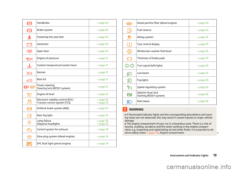
Handbrake
» page 20
Brake system
» page 20
Fastening the seat belt
» page 20
Generator
» page 20
Open door
» page 20
Engine oil pressure
» page 21
Coolant temperature/coolant level
» page 21
Bonnet
» page 21
Boot lid
» page 21
Power steering
Steering lock (KESSY system)
» page 21
Engine oil level
» page 22
Electronic stability control (ESC)
Traction control system (TCS) » page 22
» page 23
Antilock brake system (ABS)
» page 23
Rear fog light
» page 23
Lamp failure
Adaptive headlights » page 23
,
» page 23
Control system for exhaust
» page 23
Glow plug system (diesel engine)
» page 24
EPC fault light (petrol engine)
» page 24
Diesel particle filter (diesel engine)
» page 24
Fuel reserve
» page 24
Airbag system
» page 25
Tyre control display
» page 25
Windscreen washer fluid level
» page 25
Thickness of brake pads
» page 25
Turn signal (left/right).
» page 25
Low beam
» page 25
Fog lights
» page 26
Speed regulating system
» page 26
Selector lever lock
Starting (KESSY system)
» page 26
Main beam
» page 26 WARNING
■ If illuminated indicator lights and the corresponding descriptions and warn-
ing notes are not observed, this may result in severe injuries or major vehicle
damage.
■ The engine compartment of your car is a hazardous area. There is a risk of
injuries, scalding, accidents and fire when working in the engine compart-
ment, e.g. inspecting and replenishing oil and other fluids. It is essential to ob-
serve safety notes »
page 176, Engine compartment .Ð
19
Instruments and Indicator Lights
Page 64 of 235

Headlight cleaning system
First read and observe the introductory information and safety warn-
ings on page 59.
The headlights are being cleaned after the windscreen has been sprayed for the
first time and fifth time, the low beam or main beam are switched on and the
windscreen wiper lever was held in the position 5
» Fig. 47 on page 60 for about
1 second.
The headlight washer nozzles are moved forward out of the bumper by the water
pressure for cleaning the headlights.
You should remove stubborn dirt (such as insect residues) from the headlight len-
ses at regular intervals, for example when refuelling. The following guidelines
must be observed » page 170, Headlight lenses .
To ensure the proper operation of the cleaning system during the winter, any
snow should be removed from the washer nozzle fixtures and ice should be
cleared with a de-icing spray. CAUTION
Never remove the nozzles from the headlight cleaning system by hand - risk of
damage! ÐReplacing the windscreen wiper blades
Fig. 48
Windscreen wiper blade
First read and observe the introductory information and safety warn-
ings on page 59.ä
ä Before replacing the windscreen wiper blade, put the windscreen wiper arms into
the service position.
Service position for changing wiper blades
› Closing the bonnet.
› Switch the ignition off and on again.
› Then press the windscreen wiper lever into position 4
» Fig. 47
on page 60
within 10 seconds – the wiper arms move into the service position.
Removing the wiper blade
› Fold the windscreen wiper arm away from the windscreen.
› Press the locking button 1
» Fig. 48
to unlock the wiper blade and pull off in
the direction of the arrow 2
.
Attaching the wiper blade
› Push the windscreen wiper blade until the stop and it locks in place.
› Check that the wiper blade is correctly attached.
› Fold the wiper arms back to the windscreen.
› Turn on the ignition and press the windscreen wiper lever into position 4
» Fig. 47 on page 60, the windscreen wiper arms move to the home position.
Ð Replacing the rear window wiper blade (Combi)
Fig. 49
Rear window wiper blade
First read and observe the introductory information and safety warn-
ings on page 59.
Removing the wiper blade
› Fold the windscreen wiper arm away from the windscreen and position the
wiper blade at a right angle to the wiper arm » Fig. 49.
› Hold the windscreen wiper arm at the top end with one hand.
› Unlock the locking button 1
with the other hand and remove the wiper blade
in the direction of the arrow 2
.
£
ä
62 Using the system
Page 120 of 235

Switching off the cruise control system temporarily
First read and observe the introductory information and safety warn-
ings on page 116.
The cruise control system is
temporarily switched off by pressing the switchA
» Fig. 124 on page 117
into the spring-tensioned position CANCEL or by de-
pressing the brake or clutch pedal.
The set speed remains stored in the memory.
Briefly press the rocker button B
into the position RES
to resume the stored
speed after the clutch or brake pedal is released. ÐSwitching off the cruise control system completely
First read and observe the introductory information and safety warn-
ings on page 116.
›
Turn the switch A
» Fig. 124 on page 117
into the OFF position. ÐSTART/STOP
Fig. 125
Button for the START-STOP sys-
tem
The START-STOP system helps you to save fuel while at the same time reducing
harmful exhaust emissions and CO 2 emissions.
The function is automatically activated each time the ignition is switched on.
In the start-stop mode, the engine automatically switches to the vehicle's idle
phase, e.g. when stopped at traffic lights.
ä
ä Information regarding the current state of the START-STOP system is indicated in
the display of the instrument cluster.
Automatic engine shut down (stop phase)
› Stop the vehicle (where necessary, apply the handbrake).
› Take the vehicle out of gear.
› Release the clutch pedal.
Automatic renewed engine restart (start phase).
› Depress the clutch pedal.
Switching the
START-STOP system on and off
The START/STOP system can be switched on/off by pressing the button » Fig. 125.
When start-stop mode is deactivated, the indicator light in the button lights up.
If the vehicle is in the stop phase when manually switching off the system, the
engine starts immediately.
The START-STOP
system is very complex. Some of the procedures are hard to
check without servicing. The general conditions for the proper functioning of the
START-STOP system are listed in the following overview.
Conditions for the automatic engine shut down (stop phase):
› The gearshift lever is in Neutral.
› The clutch pedal is not depressed.
› The driver has fastened the seat belt.
› The driver's door is closed.
› The bonnet is closed.
› The vehicle is at a standstill.
› The factory-fitted towing device is not electrically connected to a trailer.
› The engine is at operating temperature.
› The charge state of the vehicle battery is sufficient.
› The stationary vehicle is not on a steep slope or a steep downhill section.
› The engine speed is less than 1 200 rpm.
› The temperature inside the vehicle battery is not too low or too high.
› There is sufficient pressure in the braking system.
› The difference between the outdoor- and the set temperature in the interior is
not too great.
› The vehicle speed since the last time the engine was switched off was greater
than 3 km/h.
› No cleaning of the diesel particle filter takes place
» page 24.
› The front wheels are not turned excessively (the steering angle is less than 3/4
of a steering wheel revolution).
£
118 Using the system
Page 163 of 235

Avoid short distances
Fig. 153
Principle sketch: Fuel consump-
tion in l/100 km at different tem-
peratures
Short distances result in an above-average high fuel consumption. We therefore
recommend avoiding distances of less than 4 km if the engine is cold.
A cold engine consumes the most fuel immediately after the start. Fuel consump-
tion drops to 10 litres/100 km after just 1 kilometre. The consumption stabilises
once the engine and catalytic converter have reached their operating tempera-
ture.
An important factor in this connection is also the ambient temperature. The im-
age » Fig. 153 shows the different levels of fuel consumption after driving a cer-
tain distance at a temperature of +20 °C and a temperature of -10 °C. Your vehicle
has a higher fuel consumption in the winter than in the summer. ÐChecking tyre inflation pressures
Tyres which are correctly inflated save fuel.
Always ensure the tyre inflation pressure is correct. The rolling resistance will be
increased if the tyre filling pressure is too low. This will not only increase fuel con-
sumption but also tyre wear and the driving behaviour will worsen.
Always check the tyre inflation pressure when the tyres are cold. ÐAvoid unnecessary ballast
Transporting ballast costs fuel.
Each kilogramme of weight increases the fuel consumption. It is worth checking
the boot to avoid transporting any unnecessary ballast. It is particularly in town traffic, when one is accelerating quite often, that the ve-
hicle weight will have a significant effect upon the fuel consumption. A rule of
thumb here is that an increase in weight of 100 kilograms will cause an increase
in fuel consumption of about 1 litre/100 kilometres.
At a speed of 100 - 120 km/h, your vehicle that is fitted with a roof rack cross
member without a load will use use about 10 % more fuel than normal due to the
increased aerodynamic drag.
Ð Saving electricity
When the engine is running, the alternator generates and supplies electrical pow-
er. If more electrical components of the electrical system are switched on, more
fuel is needed to operate the alternator. We therefore recommend switching off
electrical components if these are no longer required. Ð Environmental compatibility
Environmental protection has played a major role in the design, selection of mate-
rials and manufacture of your new
ŠKODA. Particular emphasis has been placed
on the following points:
Design measures
› Joints designed to be easily detached.
› Simplified disassembly due to the modular structure system.
› Improved purity of different classes of materials.
› Identification of all plastic parts in accordance with VDA Recommendation 260.
› Reduced fuel consumption and exhaust emission CO
2.
› Minimum fuel leakage during accidents.
› Reduced noise.
Choice of materials › Extensive use of recyclable material.
› Air conditioning filled with CFC-free refrigerant.
› No cadmium.
› No asbestos.
› Reduction in the “vaporisation” of plastics.
Manufacture › Solvent-free cavity protection.
› Solvent-free protection of the vehicle for transportation from the production
plant to the customer. £
161
Driving and the Environment
Page 176 of 235
Inspecting and replenishing
Fuel
ä
Introduction
This chapter contains information on the following subjects:
Refuelling 174
Unleaded petrol 175
Diesel fuel 176
The correct type of fuel for your vehicle and the tyre size and inflation pressure
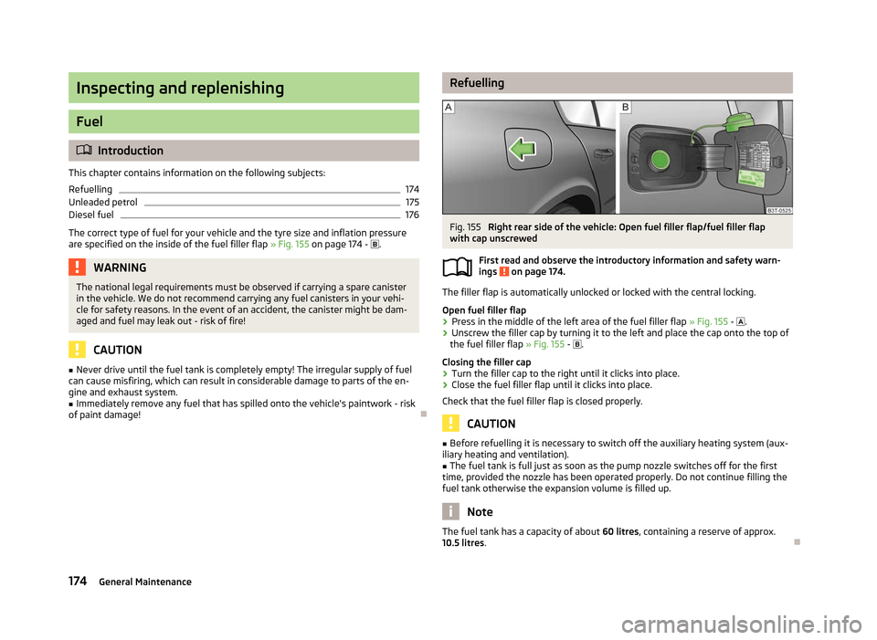
are specified on the inside of the fuel filler flap » Fig. 155 on page 174 - . WARNING
The national legal requirements must be observed if carrying a spare canister
in the vehicle. We do not recommend carrying any fuel canisters in your vehi-
cle for safety reasons. In the event of an accident, the canister might be dam-
aged and fuel may leak out - risk of fire! CAUTION
■ Never drive until the fuel tank is completely empty! The irregular supply of fuel
can cause misfiring, which can result in considerable damage to parts of the en-
gine and exhaust system. ■ Immediately remove any fuel that has spilled onto the vehicle's paintwork - risk
of paint damage! Ð Refuelling
Fig. 155
Right rear side of the vehicle: Open fuel filler flap/fuel filler flap
with cap unscrewed
First read and observe the introductory information and safety warn-
ings on page 174.
The filler flap is automatically unlocked or locked with the central locking.
Open fuel filler flap
›
Press in the middle of the left area of the fuel filler flap
» Fig. 155 - .
› Unscrew the filler cap by turning it to the left and place the cap onto the top of
the fuel filler flap » Fig. 155 - .
Closing the filler cap
› Turn the filler cap to the right until it clicks into place.
› Close the fuel filler flap until it clicks into place.
Check that the fuel filler flap is closed properly. CAUTION
■ Before refuelling it is necessary to switch off the auxiliary heating system (aux-
iliary heating and ventilation).
■ The fuel tank is full just as soon as the pump nozzle switches off for the first
time, provided the nozzle has been operated properly. Do not continue filling the
fuel tank otherwise the expansion volume is filled up. Note
The fuel tank has a capacity of about 60 litres, containing a reserve of approx.
10.5 litres . Ð
ä
174 General Maintenance
Page 189 of 235
Wheels and Tyres
Tyres
ä
Introduction
This chapter contains information on the following subjects:
Service life of tyres 188
Handling wheels and tyres 189
New wheels and tyres 189
Unidirectional tyres 190
Spare wheel 190
Full wheel trim 191
Wheel bolts 191
Wheel trim caps 191
Tyre control display 192
Wheel bolts 193
Winter tyres 193
Snow chains 193
WARNING
■ During the first 500 km, new tyres do not offer optimum grip and appropri-
ate care should therefore be taken when driving - risk of accident!
■ Never drive with damaged tyres - risk of accident!
■ Only use those tyres or wheel rims which have been approved by ŠKODA for
your model of vehicle. Failure to observe this instruction will adversely affect
the road safety of your vehicle - risk of accident!
■ The maximum permissible speed for your tyres must not be exceeded under
any circumstances - risk of an accident resulting from tyre damage and loss of
control of the vehicle.
■ If the inflation pressure is too low, the tyre must perform a higher rolling re-
sistance. At higher speeds the tyre will warm up as a result of this. This can
result in tread separation and a tyre blowout. WARNING (Continued)
■ Do not, where possible, replace individual tyres but at least replace them on
both wheels of a given axle at the same time. Always fit the tyres with the
deeper tread depth to the front wheels.
■ Never use tyres if you do not know anything about the condition and age.
■ You must have your tyres replaced with new ones at the latest when the
wear indicators have been worn down.
■ Worn tyres do not provide the necessary adhesion to the road surface at
high speeds on wet roads. One could experience
“aquaplaning” (uncontrolled
movements of the vehicle - “swimming” on a wet road surface).
■ Immediately replace damaged wheel rims or tyres.
■ Do not use summer or winter tyres that are older than 6 years or 4 years re-
spectively.
■ The wheel bolts must be clean and must turn easily. However, they must
never be treated with grease or oil.
■ If the wheel bolts are tightened to a too low tightening torque, the rim can
come loose when the car is moving - risk of accident! A tightening torque
which is too high can damage the bolts and threads and this can result in per-
manent deformation of the contact surfaces on the rim.
■ In case of incorrect treatment of the wheel bolts, the wheel can loosen
when the car is moving - risk of accident!
■ Observe the national legal regulations relating to the use of tyres and snow
chains. CAUTION
■ If a spare wheel is used that is not identical to the fitted tyres, the following
must be observed » page 190, Spare wheel.
■ The prescribed tightening torque of the wheel bolts for steel and light alloy
wheels is 120 Nm.
■ Protect the tyres from contact with oil, grease and fuel.
■ Replace any lost valve caps immediately. For the sake of the environment
Tyres which are insufficiently inflated increase your fuel consumption. £
187
Wheels and Tyres
Page 190 of 235
Note
■ We recommend that any work on the wheels or tyres is carried out by a ŠKODA
Service Partner. ■ We recommend that you use wheel rims, tyres, full wheel trims and snow chains
from
ŠKODA Original Accessories. ÐService life of tyres
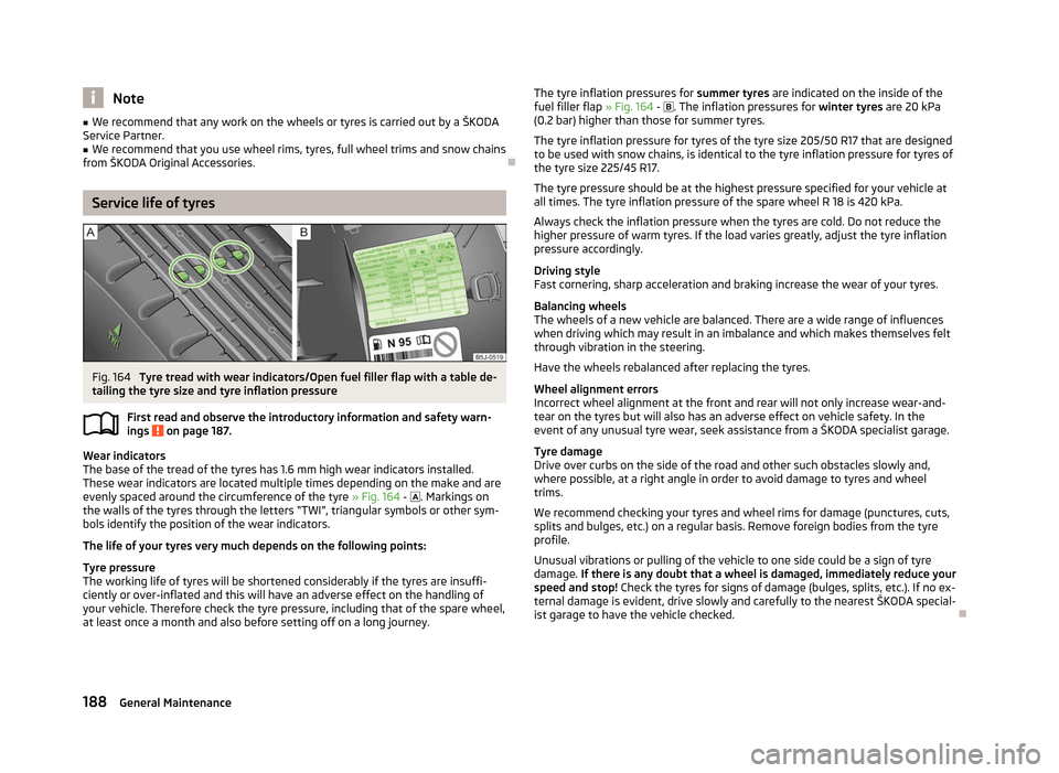
Fig. 164
Tyre tread with wear indicators/Open fuel filler flap with a table de-
tailing the tyre size and tyre inflation pressure
First read and observe the introductory information and safety warn-
ings on page 187.
Wear indicators
The base of the tread of the tyres has 1.6 mm high wear indicators installed.
These wear indicators are located multiple times depending on the make and are
evenly spaced around the circumference of the tyre » Fig. 164 - . Markings on
the walls of the tyres through the letters
“TWI”, triangular symbols or other sym-
bols identify the position of the wear indicators.
The life of your tyres very much depends on the following points:
Tyre pressure
The working life of tyres will be shortened considerably if the tyres are insuffi-
ciently or over-inflated and this will have an adverse effect on the handling of
your vehicle. Therefore check the tyre pressure, including that of the spare wheel,
at least once a month and also before setting off on a long journey.
ä The tyre inflation pressures for
summer tyres are indicated on the inside of the
fuel filler flap » Fig. 164 - . The inflation pressures for winter tyres are 20
kPa
(0.2 bar) higher than those for summer tyres.
The tyre inflation pressure for tyres of the tyre size 205/50 R17 that are designed
to be used with snow chains, is identical to the tyre inflation pressure for tyres of
the tyre size 225/45 R17.
The tyre pressure should be at the highest pressure specified for your vehicle at
all times. The tyre inflation pressure of the spare wheel R 18 is 420 kPa.
Always check the inflation pressure when the tyres are cold. Do not reduce the
higher pressure of warm tyres. If the load varies greatly, adjust the tyre inflation
pressure accordingly.
Driving style
Fast cornering, sharp acceleration and braking increase the wear of your tyres.
Balancing wheels
The wheels of a new vehicle are balanced. There are a wide range of influences
when driving which may result in an imbalance and which makes themselves felt
through vibration in the steering.
Have the wheels rebalanced after replacing the tyres.
Wheel alignment errors
Incorrect wheel alignment at the front and rear will not only increase wear-and-
tear on the tyres but will also has an adverse effect on vehicle safety. In the
event of any unusual tyre wear, seek assistance from a ŠKODA specialist garage.
Tyre damage
Drive over curbs on the side of the road and other such obstacles slowly and,
where possible, at a right angle in order to avoid damage to tyres and wheel
trims.
We recommend checking your tyres and wheel rims for damage (punctures, cuts,
splits and bulges, etc.) on a regular basis. Remove foreign bodies from the tyre
profile.
Unusual vibrations or pulling of the vehicle to one side could be a sign of tyre
damage. If there is any doubt that a wheel is damaged, immediately reduce your
speed and stop! Check the tyres for signs of damage (bulges, splits, etc.). If no ex-
ternal damage is evident, drive slowly and carefully to the nearest ŠKODA special-
ist garage to have the vehicle checked. Ð
188 General Maintenance
Page 192 of 235

Unidirectional tyres
First read and observe the introductory information and safety warn-
ings on page 187.
The direction of rotation of the tyres is marked by arrows on the wall of the tyre
.
The so specified running direction must absolutely be complied with. Only then
are the tyres able to provide the optimal properties in terms of grip, low noise,
wear-and-tear and aquaplaning.
If, in the event of a puncture, it is necessary to fit a spare wheel with a tyre with-
out a dedicated running direction or the opposite running direction, drive carefully
as the optimum characteristics of the tyre are no longer applicable in this situa-
tion. ÐSpare wheel
Fig. 166
Boot: Spare wheel
First read and observe the introductory information and safety warn-
ings on page 187.
The spare wheel is located in a well under the floor covering in the boot and is
fixed in place with a special bolt » Fig. 166.
Before removing the spare wheel, the box containing the vehicle tool kit must be
removed.
It is important to check the inflation pressure in the spare wheel (preferably every
time the tyre air pressure is checked - see sticker on the fuel filler flap »
page 188)
to ensure it is always ready to use.
ä
ä If the dimensions or design of the spare wheel differ from the tyres fitted to the
vehicle (e.g. winter tyres or low-profile tyres), it must only be used briefly in the
event of a puncture and if an appropriately cautious style of driving is adop-
ted » .
Replace it with a wheel having the appropriate mode and dimensions as soon as
possible
Temporary spare wheel
A warning label is displayed on the wheel rim of the spare wheel to indicate that
your vehicle is equipped with a temporary spare wheel.
Please observe the following when driving with a temporary spare wheel.
› The warning label must not be covered after installing the wheel.
› Do not drive faster than 80
km/h with the temporary spare wheel and pay par-
ticular attention while driving. Avoid accelerating at full throttle, sharp braking
and fast cornering.
› The inflation pressure for this spare wheel is identical to the maximum inflation
pressure of the standard tyres.
› Only use this temporary spare wheel to reach the nearest ŠKODA specialist ga-
rage as it is not intended for continuous use.
› No other summer or winter tyres must be mounted on the rim of the temporary
spare wheel R 18. WARNING
■ Never use the temporary spare wheel if it is damaged.
■ If the dimensions or design of the temporary spare wheel differ from the fit-
ted tyres, never drive faster than 80
km/h (or 50 mph). Avoid accelerating at
full throttle, sharp braking and fast cornering. CAUTION
Observe the instructions on the sticker on the temporary spare wheel. Note
The tyre pressure should be at the highest pressure specified for your vehicle at
all times. Ð
190 General Maintenance
Page 204 of 235

Inflating
›
Screw the tyre inflation hose 5
» Fig. 177
on page 201 of the air compressor
firmly onto the tyre valve.
› Check that the air release valve 7
is closed.
› Start the engine and run it in idle.
› Plug the connector 9
into 12 Volt socket »
page 84, Cigarette lighter, 12-volt
power socket.
› Switch on the air compressor with the ON and OFF switch 8
.
› Allow the air compressor to run until a pressure of 2.0 - 2.5 bar is achieved.
Maximum run time of 8 minutes » !
› Switch off the air compressor.
› If you cannot reach an air pressure of 2.0 – 2.5 bar, unscrew the tyre inflation
hose 5
from the tyre valve.
› Drive the vehicle 10 metres forwards or backwards to allow the sealing agent to
“distribute” in the tyre.
› Firmly screw the tyre inflation hose 5
back onto the tyre valve and repeat the
inflation process.
› If you cannot reach the required tyre inflation pressure here either, this means
the tyre has sustained too much damage. You cannot seal with tyre with the
breakdown kit » .
› Switch off the air compressor.
› Remove the tyre inflation hose 5
from the tyre valve.
Once a tyre inflation pressure of 2.0
– 2.5 bar is achieved, continue the journey at
a maximum speed of 80 km/h (50 mph).
Check the tyre inflation pressure after driving for 10 minutes » page 202.WARNING
■ During inflation, the tyre inflation hose and air compressor may get hot- risk
of injury! ■ Do not place the hot tyre inflation hose or hot air compressor on flammable
materials - risk of fire!
■ If you cannot inflate the tyre to at least 2.0 bar, this means the damage sus-
tained was too serious. The sealing agent cannot be used to seal the tyre. Do
not drive the vehicle. Get professional assistance! CAUTION
Switch off the air compressor after running 8 minutes at the latest - danger of
overheating! Allow the air compressor to cool a few minutes before switching it
on again. Ð Check after driving for 10 minutes
First read and observe the introductory information and safety warn-
ings on page 200.
Check the tyre inflation pressure after driving for 10 minutes!
If the tyre inflation pressure is 1.3 bar or less:
› Do not drive the vehicle!
You cannot properly seal with tyre with the break-
down kit.
› Get professional assistance.
If the tyre inflation pressure is 1.3 bar or more:
› Adjust the tyre inflation pressure to the correct value (see inside of fuel filler
cap).
› Continue driving carefully to the nearest ŠKODA specialist garage at a maxi-
mum speed of 80 km/h (50 mph). Ð Jump-starting
ä
Introduction
This chapter contains information on the following subjects:
Jump-starting 203
Jump-starting in vehicles with the START-STOP system 204
Jump-starting vehicles with the vehicle battery in the boot 204
The battery of another vehicle can be used to jump-start your vehicle if the en-
gine will not start because the battery is flat. Jump-start cables are required for
this purpose.
Both batteries must have a rated voltage of 12 V. The capacity (Ah) of the battery
supplying the power must not be significantly less than the capacity of the dis-
charged battery in your vehicle.
Jump-start cables
Only use jump-start cables which have an adequately large cross-section and in-
sulated terminal clamps. Observe the manufacturer's instructions.
Positive cable - colour coding in the majority of cases is red.
Negative cable - colour coding in the majority of cases is black. £
ä
202 Do-it-yourself
Page 210 of 235
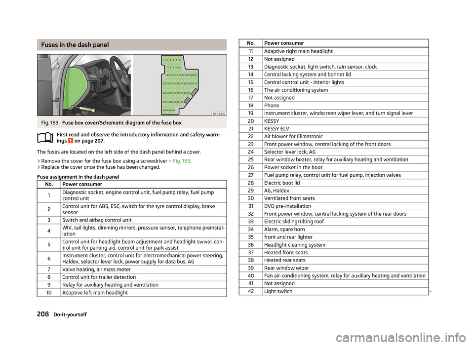
Fuses in the dash panel
Fig. 183
Fuse box cover/Schematic diagram of the fuse box
First read and observe the introductory information and safety warn-
ings on page 207.
The fuses are located on the left side of the dash panel behind a cover.
›
Remove the cover for the fuse box using a screwdriver
» Fig. 183.
› Replace the cover once the fuse has been changed.
Fuse assignment in the dash panel No. Power consumer
1 Diagnostic socket, engine control unit, fuel pump relay, fuel pump
control unit
2 Control unit for ABS, ESC, switch for the tyre control display, brake
sensor
3 Switch and airbag control unit
4 WIV, tail lights, dimming mirrors, pressure sensor, telephone preinstal-
lation
5 Control unit for headlight beam adjustment and headlight swivel, con-
trol unit for parking aid, control unit for park assist
6 Instrument cluster, control unit for electromechanical power steering,
Haldex, selector lever lock, power supply for data bus, AG
7 Valve heating, air mass meter
8 Control unit for trailer detection 9 Relay for auxiliary heating and ventilation
10 Adaptive left main headlight ä
No. Power consumer
11 Adaptive right main headlight
12 Not assigned
13 Diagnostic socket, light switch, rain sensor, clock
14 Central locking system and bonnet lid 15 Central control unit - interior lights
16 The air conditioning system 17 Not assigned
18 Phone 19 Instrument cluster, windscreen wiper lever, and turn signal lever
20 KESSY 21 KESSY ELV
22 Air blower for Climatronic
23 Front power window, central locking of the front doors
24 Selector lever lock, AG 25 Rear window heater, relay for auxiliary heating and ventilation
26 Power socket in the boot 27 Fuel pump relay, control unit for fuel pump, injection valves
28 Electric boot lid 29 AG, Haldex
30 Ventilated front seats 31 DVD pre-installation
32 Front power window, central locking system of the rear doors
33 Electric sliding/tilting roof
34 Alarm, spare horn 35 front and rear lighter
36 Headlight cleaning system 37 Heated front seats
38 Heated rear seats 39 Rear window wiper
40 Fan air-conditioning system, relay for auxiliary heating and ventilation 41 Not assigned
42 Light switch £208
Do-it-yourself