dashboard SKODA SUPERB 2014 2.G / (B6/3T) Owner's Manual
[x] Cancel search | Manufacturer: SKODA, Model Year: 2014, Model line: SUPERB, Model: SKODA SUPERB 2014 2.G / (B6/3T)Pages: 246, PDF Size: 17.16 MB
Page 17 of 246

The airbags are not deployed in the case of minor frontal and side collisions,
rear-end collisions, tilting of the vehicle and vehicle rollover.
Deployment factors
It is not possible to generally determine which deployment conditions apply to
the airbag system in every situation. An important role is played by factors
such as the type of object that the vehicle hits (hard/soft), the impact angle,
vehicle speed etc.
A decisive factor for the deployment of the airbags is the deceleration which
occurs. The control unit analyses the nature of the collision and activates the
relevant restraint system.
If the vehicle deceleration which occurs and is measured during the collision
remains below the prescribed reference values specified in the control unit,
the airbags are not deployed although the vehicle may well suffer severe dam-
age to the bodywork as a consequence of the accident.
The following airbags will be deployed in the event of a severe frontal
collision.
› Driver’s front airbag.
› Front passenger airbag.
› Driver’s knee airbag.
The following airbags will be deployed in the event of a severe side collision.
› Front side airbag on the side of the accident.
› Rear side airbag on the side of the accident.
› Head airbags on the side of the accident.
In the event of an accident in which the airbags are deployed:
› the interior lighting comes on (if the switch for the interior light is in the door
contact position),
› the hazard warning light is switched on;
› all the doors are unlocked;
› the fuel supply to the engine is interrupted.
Airbag overview
Introduction
This chapter contains information on the following subjects:
Front airbags
15
Driver’s knee airbag
16Side airbags17Head airbags18
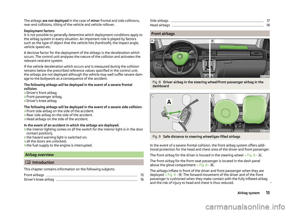
Front airbags
Fig. 8
Driver airbag in the steering wheel/front passenger airbag in the
dashboard
Fig. 9
Safe distance to steering wheel/gas-filled airbags
In the event of a severe frontal collision, the front airbag system offers addi-
tional protection for the head and chest area of the driver and front passenger.
The front airbag for the driver is housed in the steering wheel » Fig. 8 -
.
The front airbag for the front seat passenger is located in the dash panel
above the glove compartment » Fig. 8 -
.
The airbags inflate in front of the driver and front passenger when they are
deployed » Fig. 9 -
. The forward movement of the driver and of the front
passenger is cushioned when they make contact with the fully inflated airbag
and the risk of injury to head and chest is thus reduced.
15Airbag system
Page 18 of 246

WARNINGInformation on correct seated position■For the driver and front passenger, it is important to maintain a distance
of at least 25 cm from the steering wheel or dashboard A
» Fig. 9 . Not
maintaining this minimum distance will mean that the airbag system will
not be able to properly protect you - hazard! The front seats and the head
restraints must always also be correctly adjusted to match the body size of
the occupant.
■
The airbag develops enormous forces when triggered, which can lead to
injuries if the sitting position or seated position is not correct.
■
There must not by any further persons, animals or objects positioned be-
tween the front seated occupants and the deployment area of the airbag.
WARNINGFront airbag and transporting children■Never transport children on the front seat of a vehicle without using a
proper restraint system. If airbags are deployed in the event of an accident,
the child might suffer severe or even fatal injuries!■
The front passenger airbag must be deactivated if using a rear-facing
child seat on the front passenger seat » page 19, Deactivating airbags . If
this is not done, there is a risk of the child suffering severe or even fatal
injuries if the front passenger airbag is deployed. When transporting a child
on the front passenger seat, pay attention to any relevant national regula-
tions regarding the use of child safety seats.
WARNINGGeneral information■The steering wheel and the surface of the airbag module in the dash pan-
el on the passenger side must not have stickers attached, be covered or
modified in any other way. These parts should only be cleaned with a cloth
that is dry or has been moistened with water. No objects such as cup hold-
ers, mobile phone mounts, etc. must be attached to the covers of the air-
bag modules or be located within their immediate vicinity.■
Never place objects on the surface of the front passenger airbag module
in the dash panel.
Note■ In vehicles with head airbags, the word AIRBAG can be seen on the steering
wheel.■
In vehicles with front passenger airbags, the word AIRBAG is located on the
dash panel on the passenger side.
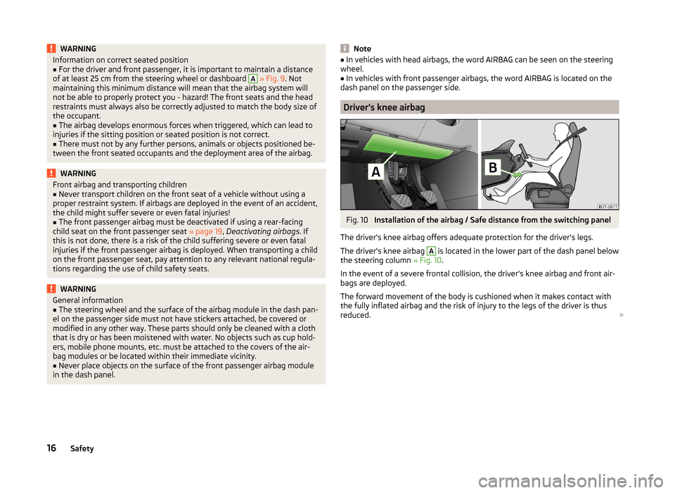
Driver’s knee airbag
Fig. 10
Installation of the airbag / Safe distance from the switching panel
The driver's knee airbag offers adequate protection for the driver's legs.
The driver's knee airbag
A
is located in the lower part of the dash panel below
the steering column » Fig. 10.
In the event of a severe frontal collision, the driver's knee airbag and front air-
bags are deployed.
The forward movement of the body is cushioned when it makes contact with
the fully inflated airbag and the risk of injury to the legs of the driver is thus
reduced.
16Safety
Page 207 of 246

WARNING■A tyre filled with sealant has the same driving characteristics as a stand-
ard tyre.■
Do not travel faster than 80 km/h.
■
Avoid accelerating at full throttle, sharp braking and fast cornering.
■
Check the tyre pressure after driving for 10 minutes.
■
The sealant is hazardous to heath. Remove immediately if it comes into
contact with the skin.
For the sake of the environment
Used sealant or sealant whose expiry date has passed must be disposed of in
accordance with environmental protection regulations.
Note
■ Observe the manufacturer's usage instructions for the breakdown kit.■A new bottle of sealant can be purchased from ŠKODA Original Parts.■
Immediately replace the tyre that was repaired using the breakdown kit, or
consult a specialist garage about repair options.
Breakdown kit
Fig. 181
Principle sketch: Components of the breakdown kit
Read and observe
on page 205 first.
The kit is located in a box under the floor covering in the luggage compart-
ment.
Components of the breakdown kit » Fig. 181
Valve remover
Sticker with speed designation “max. 80 km/h”/“max. 50 mph” Inflation hose with plug
Air compressor
Tyre inflation hose
Tyre inflation pressure indicator
Air release valve
ON and OFF switch
12 volt cable connector
Tyre inflator bottle with sealing agent
Replacement valve core
The valve remover 1
has a slot at its lower end which fits into the valve core.
This is the only way in which you can remove and re-install the valve core from
the tyre valve. The same also applies to the replacement valve core
11
.
Preparations for using the breakdown kit
Read and observe
on page 205 first.
The following preparatory work must be carried out before using the break-
down kit.
›
Park the vehicle as far away as possible from the flow of traffic. Park on as
flat and firm a surface as possible.
›
If you are in flowing traffic, switch on the hazard warning light system and
set up the warning triangle at the prescribed distance! The national legal re-
quirements must be observed.
›
Have all the occupants get out. The passengers should not stand on the
road (instead they should remain behind a crash barrier, for instance) while
the wheel is being changed.
›
Switch off the engine and move the gearshift lever into Neutral or move the
selector lever on the automatic gearbox into position P.
›
Apply the handbrake firmly.
›
Check that you can carry out the repairs with the breakdown kit » page 204.
Uncouple a trailer.
›
Remove the breakdown kit from the boot.
›
Stick the sticker
2
» Fig. 181 on page 205 on the dashboard in the driver's
field of view.
1234567891011205Emergency equipment and self-help