fog light SKODA SUPERB 2014 2.G / (B6/3T) Owner's Manual
[x] Cancel search | Manufacturer: SKODA, Model Year: 2014, Model line: SUPERB, Model: SKODA SUPERB 2014 2.G / (B6/3T)Pages: 246, PDF Size: 17.16 MB
Page 34 of 246
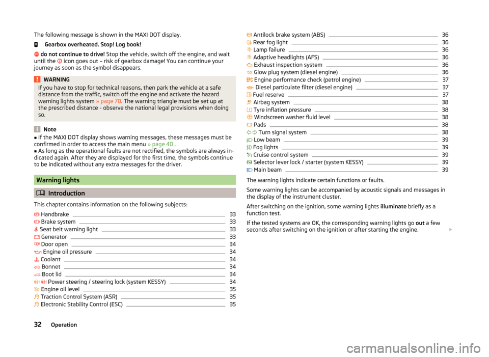
The following message is shown in the MAXI DOT display.Gearbox overheated. Stop! Log book!
do not continue to drive! Stop the vehicle, switch off the engine, and wait
until the
icon goes out – risk of gearbox damage! You can continue your
journey as soon as the symbol disappears.WARNINGIf you have to stop for technical reasons, then park the vehicle at a safe
distance from the traffic, switch off the engine and activate the hazard
warning lights system » page 70. The warning triangle must be set up at
the prescribed distance - observe the national legal provisions when doing
so.
Note
■ If the MAXI DOT display shows warning messages, these messages must be
confirmed in order to access the main menu » page 40 .■
As long as the operational faults are not rectified, the symbols are always in-
dicated again. After they are displayed for the first time, the symbols continue
to be indicated without any extra messages for the driver.
Warning lights
Introduction
This chapter contains information on the following subjects:
Handbrake
33
Brake system
33
Seat belt warning light
33
Generator
33
Door open
34
Engine oil pressure
34
Coolant
34
Bonnet
34
Boot lid
34
Power steering / steering lock (system KESSY)
34
Engine oil level
35
Traction Control System (ASR)
35
Electronic Stability Control (ESC)
35 Antilock brake system (ABS)36 Rear fog light36
Lamp failure
36
Adaptive headlights (AFS)
36
Exhaust inspection system
36
Glow plug system (diesel engine)
36
Engine performance check (petrol engine)
37
Diesel particulate filter (diesel engine)
37
Fuel reserve
37
Airbag system
38
Tyre inflation pressure
38
Windscreen washer fluid level
38
Pads
38
Turn signal system
38
Low beam
39
Fog lights
39
Cruise control system
39
Selector lever lock / starter (system KESSY)
39
Main beam
39
The warning lights indicate certain functions or faults.
Some warning lights can be accompanied by acoustic signals and messages in
the display of the instrument cluster.
After switching on the ignition, some warning lights illuminate briefly as a
function test.
If the tested systems are OK, the corresponding warning lights go out a few
seconds after switching on the ignition or after starting the engine.
32Operation
Page 38 of 246
If the warning light illuminates immediately after you start the engine, the
ESC might be switched off due to technical reasons.›
Switch the ignition off and on again.
The ESC is fully functional again if the warning light
no longer illuminates
after you switch the engine back on.
Further information » page 151.
Note
The warning light illuminates after the ignition is switched on if the vehi-
cle's battery has been disconnected and reconnected. If the warning light
does not go out after moving a short distance, this means there is an error in
the system. Seek assistance from a specialist garage immediately.
Antilock brake system (ABS)
Read and observe
on page 33 first.
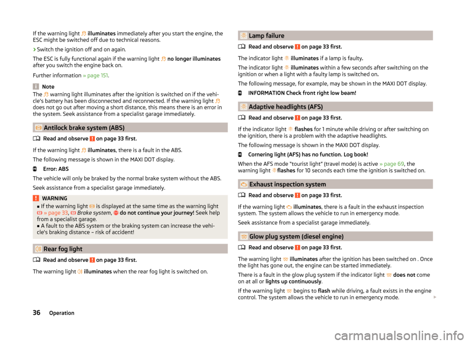
If the warning light
illuminates , there is a fault in the ABS.
The following message is shown in the MAXI DOT display. Error: ABS
The vehicle will only be braked by the normal brake system without the ABS.
Seek assistance from a specialist garage immediately.
WARNING■ If the warning light is displayed at the same time as the warning light
» page 33 , Brake system , do not continue your journey! Seek help
from a specialist garage.■
A fault to the ABS system or the braking system can increase the vehi-
cle's braking distance – risk of accident!
Rear fog light
Read and observe
on page 33 first.
The warning light
illuminates when the rear fog light is switched on.
Lamp failure
Read and observe
on page 33 first.
The indicator light
illuminates if a lamp is faulty .
The indicator light
illuminates within a few seconds after switching on the
ignition or when a light with a faulty lamp is switched on .
The following message, for example, may be shown in the MAXI DOT display. INFORMATION Check front right low beam!
Adaptive headlights (AFS)
Read and observe
on page 33 first.
If the indicator light
flashes for 1 minute while driving or after switching on
the ignition, there is a problem with the adaptive headlights.
The following message is shown in the MAXI DOT display. Cornering light (AFS) has no function. Log book!
When the AFS mode “tourist light” (travel mode) is active » page 69, the
warning light flashes
for 10 seconds each time the ignition is switched on.
Exhaust inspection system
Read and observe
on page 33 first.
If the warning light
illuminates , there is a fault in the exhaust inspection
system. The system allows the vehicle to run in emergency mode.
Seek assistance from a specialist garage immediately.
Glow plug system (diesel engine)
Read and observe
on page 33 first.
The warning light
illuminates after the ignition has been switched on . Once
the light has gone out, the engine can be started immediately.
There is a fault in the glow plug system if the indicator light
does not come
on at all or lights up continuously .
If the warning light begins to
flash while driving, a fault exists in the engine
control. The system allows the vehicle to run in emergency mode.
36Operation
Page 41 of 246
Switching off the hazard warning light system is switched on will cause all of
the turn signal lights as well as both warning lights to flash.
Low beam
Read and observe
on page 33 first.
The warning light
illuminates when low beam is selected.
Fog lights
Read and observe
on page 33 first.
The warning light
illuminates when the fog lights are operating.
Cruise control system
Read and observe
on page 33 first.
The warning light
illuminates when the cruise control is active.
Selector lever lock / starter (system KESSY)
Read and observe
on page 33 first.
If the warning light
illuminates , operate the brake pedal. This is necessary
to move the selector lever from position P and N » page 143 or to start the en-
gine in vehicles with the KESSY system » page 139.
Main beam
Read and observe
on page 33 first.
The warning light
illuminates when the main beam is selected or when the
headlight flasher is operated.
Information system
Driver information system
Introduction
This chapter contains information on the following subjects:
Using the information system
40
Display a low temperature
40
Gear recommendation
40
Door, boot or engine compartment warning
41
The information system provides the driver with alerts and messages about
individual vehicle systems. This information and advice is shown in the instru-
ment cluster display or indicated by the illumination of the corresponding indi-
cator light in the instrument cluster.
The information system provides the following information and instructions (depending on vehicle equipment).
› Data relating to the multi-function display (MFD)
» page 41.
› Data relating to the Maxi DOT display
» page 44.
› Service interval display
» page 46.
› Auto Check Control
» page 31.
› Selector lever positions for an automatic gearbox
» page 142.
WARNINGConcentrate fully at all times on your driving! As the driver, you are fully re-
sponsible for the operation of your vehicle.39Information system
Page 67 of 246
WARNINGWhen operating the sunshade, proceed with caution to avoid causing
crushing injuries – risk of injury!
Convenience operation of sliding / tilting roof
Read and observe
on page 63 first.
The sliding / tilting roof can be operated by locking or unlocking using the key
or using the KESSY system with the aid of the sensor
1
» Fig. 32 on page 50 .
Closing
›
Press and hold the symbol button on the key or hold the key in the locking
cylinder of the driver's door in the lock position, or for the KESSY system,
keep your finger on the sensor
1
» Fig. 32 on page 50 » .
By releasing the lock or lifting your finger off the sensor
1
when using the
KESSY system, the closing process is immediately interrupted.
Tilting roof
›
Press the button on the remote control key.
WARNINGClose the sliding/tilting roof carefully – risk of injury. The force limiter does
not operate with the convenience closing.Lights and visibility
Lights
Introduction
This chapter contains information on the following subjects:
Parking and low beam lights
66
Daylight running lights (DAY LIGHT)
67
Turn signal and main beam
67
Automatic driving lamp control
68
Adaptive headlights (AFS)
68
Fog lights
69
Fog lights with the CORNER function
69
Rear fog light
69
COMING HOME / LEAVING HOME
70
Hazard warning light system
70
Parking lights
71
Unless otherwise stated, the lights only work when the ignition is switched
on.
The arrangement of the controls right-hand drive models may differ from the
layout shown in » Fig. 48 on page 66 . The symbols which mark the positions
of the controls are identical.
Keep the headlights lenses clean. The following guidelines must be ob-
served » page 175 , Headlight lenses .
WARNING■
The activation of the lights should only be undertaken in accordance with
national legal requirements.■
The driver is always responsible for the correct settings and use of the
lights.
65Lights and visibility
Page 68 of 246
WARNING (Continued)■The automatic driving lamp control only operates as a support and
does not release the driver from his responsibility to check the light and, if
necessary, to switch on the light depending on the given light conditions.
The light sensor cannot, for example, detect rain or snow. Under these con-
ditions we recommend switching on the low beam or fog lights!■
Never drive with only the side lights on! The side lights are not bright
enough to light up the road sufficiently in front of you or to be seen by oth-
er oncoming traffic. Therefore always switch on the low beam when it is
dark or if visibility is poor.
Note
The headlights may mist up temporarily. When the driving lights are switched
on, the light outlet surfaces are free from mist after a short period, although
the headlight lenses may still be misted up in the peripheral areas. This mist
has no influence on the life of the lighting system.
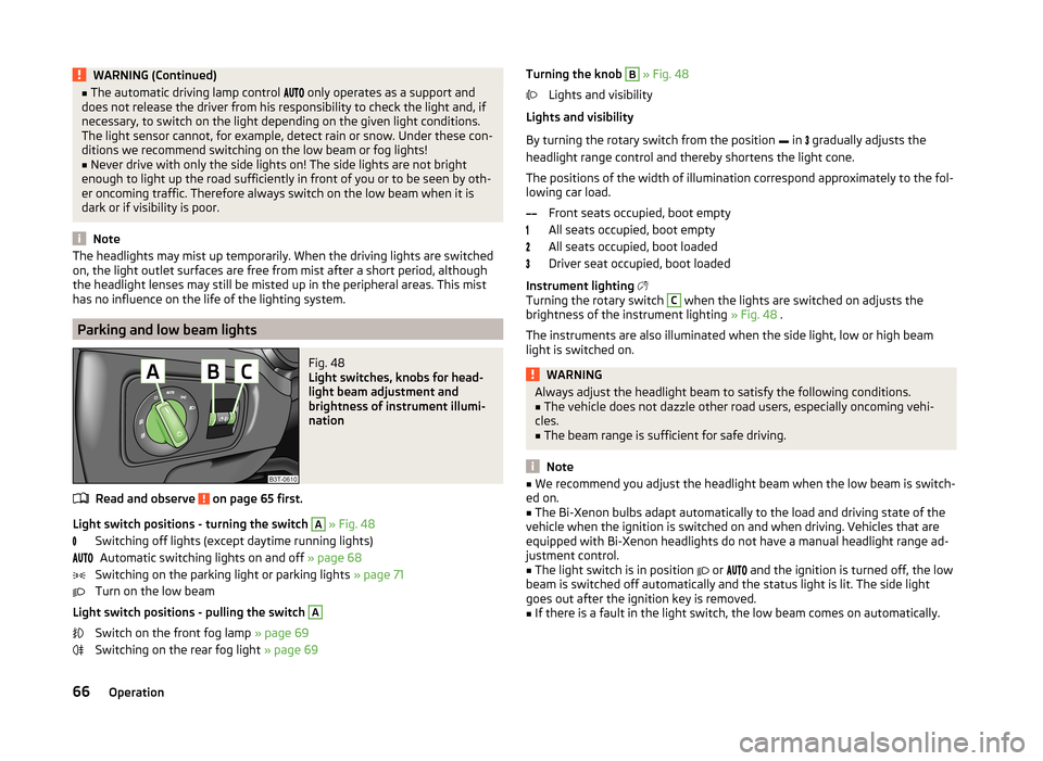
Parking and low beam lights
Fig. 48
Light switches, knobs for head-
light beam adjustment and
brightness of instrument illumi-
nation
Read and observe on page 65 first.
Light switch positions - turning the switch
A
» Fig. 48
Switching off lights (except daytime running lights) Automatic switching lights on and off » page 68
Switching on the parking light or parking lights » page 71
Turn on the low beam
Light switch positions - pulling the switch
A
Switch on the front fog lamp » page 69
Switching on the rear fog light » page 69
Turning the knob B » Fig. 48
Lights and visibility
Lights and visibility
By turning the rotary switch from the position in
gradually adjusts the
headlight range control and thereby shortens the light cone.
The positions of the width of illumination correspond approximately to the fol-
lowing car load.
Front seats occupied, boot empty
All seats occupied, boot empty
All seats occupied, boot loaded
Driver seat occupied, boot loaded
Instrument lighting
Turning the rotary switch C
when the lights are switched on adjusts the
brightness of the instrument lighting » Fig. 48 .
The instruments are also illuminated when the side light, low or high beam
light is switched on.
WARNINGAlways adjust the headlight beam to satisfy the following conditions.■The vehicle does not dazzle other road users, especially oncoming vehi-
cles.■
The beam range is sufficient for safe driving.
Note
■ We recommend you adjust the headlight beam when the low beam is switch-
ed on.■
The Bi-Xenon bulbs adapt automatically to the load and driving state of the
vehicle when the ignition is switched on and when driving. Vehicles that are
equipped with Bi-Xenon headlights do not have a manual headlight range ad-
justment control.
■
The light switch is in position
or
and the ignition is turned off, the low
beam is switched off automatically and the status light is lit. The side light
goes out after the ignition key is removed.
■
If there is a fault in the light switch, the low beam comes on automatically.
66Operation
Page 71 of 246
Dynamic cornering lights
The cone of light in front of the vehicle is adjusted to the steering angle so
that the road in the curve is illuminated. This function is active at speeds
greater than 10 km.h and in all AFS modes.
Tourist lights (Travel mode)
This mode makes it possible to drive in countries with opposing traffic system
(driving on the left/right) without dazzling the oncoming vehicles.
When this mode is active, the above-mentioned modes and the side swivel of
the headlights is deactivated.
This mode can be enabled or disabled via the Maxi DOT display in the Travel
mode » page 45 , Lights and Visibility menu option.WARNINGIf the AFS system is defective, the headlights are automatically lowered to
the emergency position, which prevents a possible dazzling of oncoming
traffic. This reduces the cone of light in front of the vehicle. Drive carefully
and visit a specialist garage as soon as possible.
Note
When the “tourist light” mode is active, the warning light flashes for 10 sec-
onds each time the ignition is switched on.
Fog lights
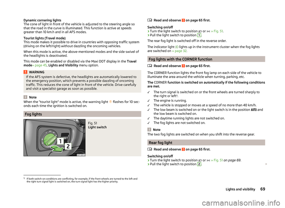
Fig. 51
Light switch
Read and observe on page 65 first.
Switching on/off
›
Turn the light switch to position
or
» Fig. 51 .
›
Pull the light switch to position
1
.
The rear fog light is switched off in the reverse order.
The indicator light
lights up in the instrument cluster when the fog lights
are switched on » page 32.
Fog lights with the CORNER function
Read and observe
on page 65 first.
The CORNER function lights the front fog lamp on each side of the vehicle to
illuminate the area around the vehicle when turning, parking, etc.
The CORNER function is switched on automatically if the following conditions
are met.
The turn signal is switched on or the front wheels are turned sharply to
the right or left 1)
.
The engine is running.
The vehicle is stopped or moves at a speed of no more than 40 km/h.
The low beam is switched on or the light switch is in the position and
the low beam is switched on.
The daytime running lights are not switched on.
The fog lights are not switched on.
Note
The two fog lights are switched on when you shift into the reverse gear.
Rear fog light
Read and observe
on page 65 first.
Switching on/off
›
Turn the light switch to position or
» Fig. 51 on page 69 .
›
Pull the light switch to position
2
.
1)
If both switch-on conditions are conflicting, for example, if the front wheels are turned to the left and
the right turn signal light is switched on, the turn signal light has the higher priority.
69Lights and visibility
Page 72 of 246
The rear fog light is switched off in the reverse order.
The warning light
lights up in the instrument cluster when the rear fog light
is switched on » page 32.
When in reverse gear only the rear fog lamp illuminates on the driver's side.
Only the rear fog light on the trailer lights up if the vehicle has a factory-fitted
towing device or a towing device from ŠKODA original accessories and it is
driven with a trailer.
COMING HOME / LEAVING HOME
Read and observe
on page 65 first.
COMING HOME/LEAVING HOME (hereafter referred to only as function)
switches on the lights for a short time after leaving the vehicle or when ap-
proaching the vehicle.
The daytime running lights are switched on automatically if the following
conditions are met:
The light switch is in the position » Fig. 50
on page 68 .
The visibility in the vehicle environment is reduced.
The ignition is switched off.
The parking aid is activated.
The function switches on the following light, depending on the equipment
fitted.
› Parking lights
› Low beam
› Entry lighting in the exterior mirrors
› Licence plate light
The light is controlled on the basis of information that is collected from the
holder mounted in the rear-view mirror sensor » page 68 .
COMING HOME
The light turns on automatically when you open the driver's door on (within 60
seconds of turning off the ignition).
The light turns off 10 seconds after closing all the doors and the boot lid or af-
ter the pre-set time has expired.
If a door or the boot lid remains open, the light goes out after 60 seconds.
LEAVING HOME
The light turns on automatically after the vehicle is unlocked with the remote
control.
The light turns off after 10 seconds or after a pre-set time or after the vehicle
is locked.
Activate/deactivate the function
The functions and settings of the illumination time can be activated/deactiva- ted via the MAXI DOT display in the menu items Coming Home or Leaving
Home » page 45 .
CAUTION
■
Do not attach any stickers or similar objects in front of the light sensor on
the windscreen to avoid impairing the function or its reliability.■
If this function is activated constantly, the battery will be heavily discharged
particularly in short-haul traffic.
Hazard warning light system
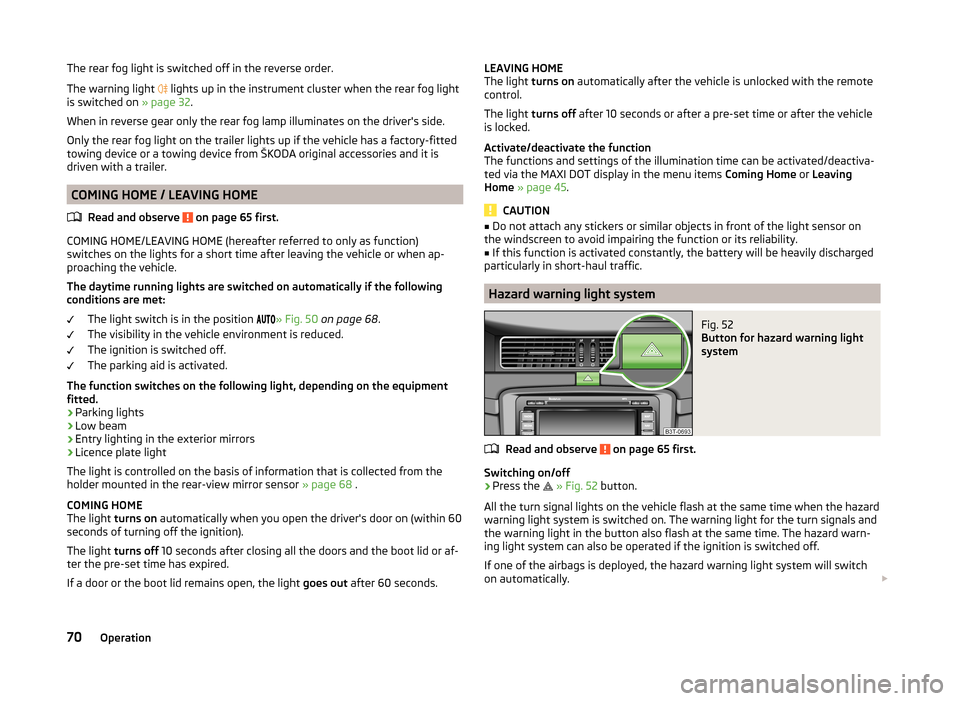
Fig. 52
Button for hazard warning light
system
Read and observe on page 65 first.
Switching on/off
›
Press the
» Fig. 52 button.
All the turn signal lights on the vehicle flash at the same time when the hazard
warning light system is switched on. The warning light for the turn signals and
the warning light in the button also flash at the same time. The hazard warn-
ing light system can also be operated if the ignition is switched off.
If one of the airbags is deployed, the hazard warning light system will switch
on automatically.
70Operation
Page 114 of 246
adjustingRead and observe
on page 110 first.
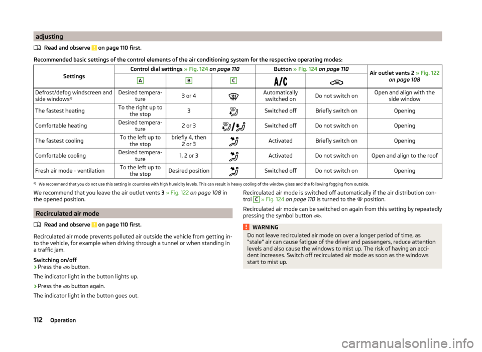
Recommended basic settings of the control elements of the air conditioning system for the respective operating modes:
SettingsControl dial settings » Fig. 124 on page 110Button » Fig. 124 on page 110Air outlet vents 2 » Fig. 122
on page 108ABCDefrost/defog windscreen and
side windows a)Desired tempera-
ture3 or 4Automaticallyswitched onDo not switch onOpen and align with the side windowThe fastest heatingTo the right up tothe stop3Switched offBriefly switch onOpeningComfortable heatingDesired tempera- ture2 or 3Switched offDo not switch onOpeningThe fastest coolingTo the left up to
the stopbriefly 4, then 2 or 3ActivatedBriefly switch onOpeningComfortable coolingDesired tempera- ture1, 2 or 3ActivatedDo not switch onOpen and align to the roofFresh air mode - ventilationTo the left up tothe stopDesired positionSwitched offDo not switch onOpeninga)
We recommend that you do not use this setting in countries with high humidity levels. This can result in heavy cooling of the window glass and the following fogging from outside.
We recommend that you leave the air outlet vents 3 » Fig. 122 on page 108 in
the opened position.
Recirculated air mode
Read and observe
on page 110 first.
Recirculated air mode prevents polluted air outside the vehicle from getting in-to the vehicle, for example when driving through a tunnel or when standing in
a traffic jam.
Switching on/off
›
Press the button.
The indicator light in the button lights up.
›
Press the button again.
The indicator light in the button goes out.
Recirculated air mode is switched off automatically if the air distribution con-
trol C » Fig. 124 on page 110 is turned to the position.
Recirculated air mode can be switched on again from this setting by repeatedly pressing the symbol button
.WARNINGDo not leave recirculated air mode on over a longer period of time, as
“stale” air can cause fatigue of the driver and passengers, reduce attention
levels and also cause the windows to mist up. The risk of having an acci-
dent increases. Switch off recirculated air mode as soon as the windows
start to mist up.112Operation
Page 221 of 246
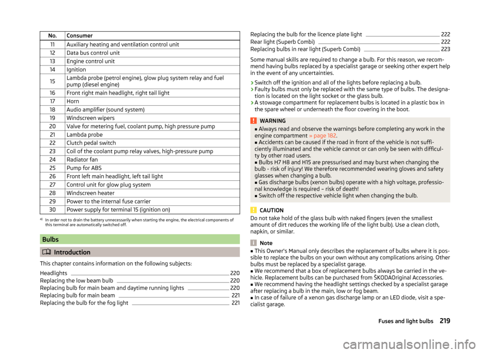
No.Consumer11Auxiliary heating and ventilation control unit12Data bus control unit13Engine control unit14Ignition15Lambda probe (petrol engine), glow plug system relay and fuel
pump (diesel engine)16Front right main headlight, right tail light17Horn18Audio amplifier (sound system)19Windscreen wipers20Valve for metering fuel, coolant pump, high pressure pump21Lambda probe22Clutch pedal switch23Coil of the coolant pump relay valves, high-pressure pump24Radiator fan25Pump for ABS26Front left main headlight, left tail light27Control unit for glow plug system28Windscreen heater29Power to the internal fuse carrier30Power supply for terminal 15 (ignition on)a)
In order not to drain the battery unnecessarily when starting the engine, the electrical components of
this terminal are automatically switched off.
Bulbs
Introduction
This chapter contains information on the following subjects:
Headlights
220
Replacing the low beam bulb
220
Replacing bulb for main beam and daytime running lights
220
Replacing bulb for main beam
221
Replacing the bulb for the fog light
221Replacing the bulb for the licence plate light222Rear light (Superb Combi)222
Replacing bulbs in rear light (Superb Combi)
223
Some manual skills are required to change a bulb. For this reason, we recom-
mend having bulbs replaced by a specialist garage or seeking other expert help
in the event of any uncertainties.
› Switch off the ignition and all of the lights before replacing a bulb.
› Faulty bulbs must only be replaced with the same type of bulbs. The designa-
tion is located on the light socket or the glass bulb.
› A stowage compartment for replacement bulbs is located in a plastic box in
the spare wheel or underneath the floor covering in the boot.
WARNING■ Always read and observe the warnings before completing any work in the
engine compartment » page 182.■
Accidents can be caused if the road in front of the vehicle is not suffi-
ciently illuminated and the vehicle cannot or can only be seen with difficul-
ty by other road users.
■
Bulbs H7 H8 and H15 are pressurised and may burst when changing the
bulb - risk of injury! We therefore recommended wearing gloves and safety
glasses when changing a bulb.
■
Gas discharge bulbs (xenon bulbs) operate with a high voltage, professio-
nal knowledge is required – risk of death!
■
Switch off the respective vehicle light when changing the bulb.
CAUTION
Do not take hold of the glass bulb with naked fingers (even the smallest
amount of dirt reduces the working life of the light bulb). Use a clean cloth,
napkin, or similar.
Note
■ This Owner's Manual only describes the replacement of bulbs where it is pos-
sible to replace the bulbs on your own without any complications arising. Other
bulbs must be replaced by a specialist garage.■
We recommend that a box of replacement bulbs always be carried in the ve-
hicle. Replacement bulbs can be purchased from ŠKODAOriginal Accessories.
■
We recommend having the headlight settings checked by a specialist garage
after replacing a bulb in the main, low or fog beam.
■
In case of failure of a xenon gas discharge lamp or an LED diode, visit a spe-
cialist garage.
219Fuses and light bulbs
Page 223 of 246
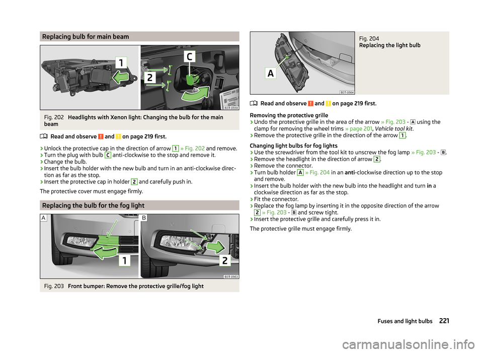
Replacing bulb for main beamFig. 202
Headlights with Xenon light: Changing the bulb for the main
beam
Read and observe
and on page 219 first.
›
Unlock the protective cap in the direction of arrow
1
» Fig. 202 and remove.
›
Turn the plug with bulb
C
anti-clockwise to the stop and remove it.
›
Change the bulb.
›
Insert the bulb holder with the new bulb and turn in an anti-clockwise direc-
tion as far as the stop.
›
Insert the protective cap in holder
2
and carefully push in.
The protective cover must engage firmly.
Replacing the bulb for the fog light
Fig. 203
Front bumper: Remove the protective grille/fog light
Fig. 204
Replacing the light bulb
Read and observe and on page 219 first.
Removing the protective grille
›
Undo the protective grille in the area of the arrow » Fig. 203 -
using the
clamp for removing the wheel trims » page 201, Vehicle tool kit .
›
Remove the protective grille in the direction of the arrow
1
.
Changing light bulbs for fog lights
›
Use the screwdriver from the tool kit to unscrew the fog lamp » Fig. 203 -
.
›
Remove the headlight in the direction of arrow
2
.
›
Remove the connector.
›
Turn bulb holder
A
» Fig. 204 in an anti-clockwise direction up to the stop
and remove.
›
Insert the bulb holder with the new bulb into the headlight and turn in a
clockwise direction as far as the stop.
›
Fit the connector.
›
Replace the fog lamp by inserting it in the opposite direction of the arrow
2
» Fig. 203 -
and screw tight.
›
Insert the protective grille and carefully press it in.
The protective grille must engage firmly.
221Fuses and light bulbs