fuel type SKODA SUPERB 2014 2.G / (B6/3T) Owner's Manual
[x] Cancel search | Manufacturer: SKODA, Model Year: 2014, Model line: SUPERB, Model: SKODA SUPERB 2014 2.G / (B6/3T)Pages: 246, PDF Size: 17.16 MB
Page 17 of 246
The airbags are not deployed in the case of minor frontal and side collisions,
rear-end collisions, tilting of the vehicle and vehicle rollover.
Deployment factors
It is not possible to generally determine which deployment conditions apply to
the airbag system in every situation. An important role is played by factors
such as the type of object that the vehicle hits (hard/soft), the impact angle,
vehicle speed etc.
A decisive factor for the deployment of the airbags is the deceleration which
occurs. The control unit analyses the nature of the collision and activates the
relevant restraint system.
If the vehicle deceleration which occurs and is measured during the collision
remains below the prescribed reference values specified in the control unit,
the airbags are not deployed although the vehicle may well suffer severe dam-
age to the bodywork as a consequence of the accident.
The following airbags will be deployed in the event of a severe frontal
collision.
› Driver’s front airbag.
› Front passenger airbag.
› Driver’s knee airbag.
The following airbags will be deployed in the event of a severe side collision.
› Front side airbag on the side of the accident.
› Rear side airbag on the side of the accident.
› Head airbags on the side of the accident.
In the event of an accident in which the airbags are deployed:
› the interior lighting comes on (if the switch for the interior light is in the door
contact position),
› the hazard warning light is switched on;
› all the doors are unlocked;
› the fuel supply to the engine is interrupted.
Airbag overview
Introduction
This chapter contains information on the following subjects:
Front airbags
15
Driver’s knee airbag
16Side airbags17Head airbags18
Front airbags
Fig. 8
Driver airbag in the steering wheel/front passenger airbag in the
dashboard
Fig. 9
Safe distance to steering wheel/gas-filled airbags
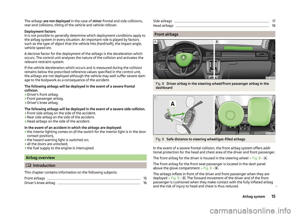
In the event of a severe frontal collision, the front airbag system offers addi-
tional protection for the head and chest area of the driver and front passenger.
The front airbag for the driver is housed in the steering wheel » Fig. 8 -
.
The front airbag for the front seat passenger is located in the dash panel
above the glove compartment » Fig. 8 -
.
The airbags inflate in front of the driver and front passenger when they are
deployed » Fig. 9 -
. The forward movement of the driver and of the front
passenger is cushioned when they make contact with the fully inflated airbag
and the risk of injury to head and chest is thus reduced.
15Airbag system
Page 32 of 246
Display types » Fig. 22 .
Segment display
MAXI DOT display
CAUTION
Pull out the ignition key if coming in contact with the display (e.g. when clean-
ing) to prevent any possible damage. On vehicles with the KESSY system,
switch off the ignition and open the driver's door.
Fuel gauge
Fig. 23
Fuel gauge
Read and observe on page 28 first.
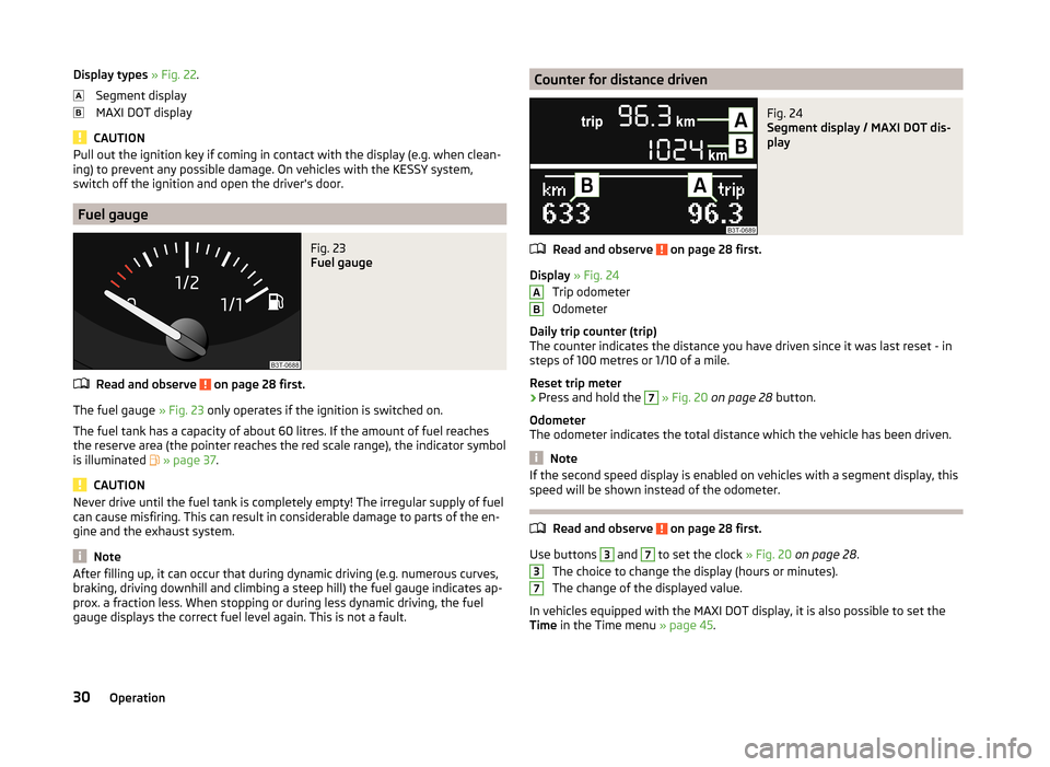
The fuel gauge » Fig. 23 only operates if the ignition is switched on.
The fuel tank has a capacity of about 60 litres. If the amount of fuel reaches
the reserve area (the pointer reaches the red scale range), the indicator symbol
is illuminated
» page 37 .
CAUTION
Never drive until the fuel tank is completely empty! The irregular supply of fuel
can cause misfiring. This can result in considerable damage to parts of the en-
gine and the exhaust system.
Note
After filling up, it can occur that during dynamic driving (e.g. numerous curves,
braking, driving downhill and climbing a steep hill) the fuel gauge indicates ap-
prox. a fraction less. When stopping or during less dynamic driving, the fuel
gauge displays the correct fuel level again. This is not a fault.Counter for distance drivenFig. 24
Segment display / MAXI DOT dis-
play
Read and observe on page 28 first.
Display » Fig. 24
Trip odometer
Odometer
Daily trip counter (trip)
The counter indicates the distance you have driven since it was last reset - in
steps of 100 metres or 1/10 of a mile.
Reset trip meter
›
Press and hold the
7
» Fig. 20 on page 28 button.
Odometer
The odometer indicates the total distance which the vehicle has been driven.
Note
If the second speed display is enabled on vehicles with a segment display, this
speed will be shown instead of the odometer.
Read and observe on page 28 first.
Use buttons
3
and
7
to set the clock » Fig. 20 on page 28 .
The choice to change the display (hours or minutes).
The change of the displayed value.
In vehicles equipped with the MAXI DOT display, it is also possible to set the
Time in the Time menu » page 45.
AB3730Operation
Page 181 of 246
WARNING (Continued)■The seat belts must not be allowed to come into contact with corrosive
liquids (e.g. acids).■
Check the condition of all the seat belts on a regular basis. If any damage
to the belt webbing, seat belt connections, inertia reel or lock is detected,
the seat belt must be replaced by a specialist garage.
■
The seat belts must be fully dried before being rolled up.
Inspecting and replenishing
Fuel
Introduction
This chapter contains information on the following subjects:
Refuelling
180
Unleaded petrol
180
Diesel fuel
181
The correct grades of fuel for your vehicle are stated on a sticker affixed to the
inside of the fuel filler flap » Fig. 159 on page 180 -
.
WARNINGThe national legal requirements must be observed if carrying a spare canis-
ter in the vehicle. We do not recommend carrying any fuel canisters in your
vehicle for safety reasons. in the event of an accident, these canisters can
become damaged and fuel may escape – risk of fire!
CAUTION
■ Never drive until the fuel tank is completely empty! The irregular supply of
fuel can cause misfiring, which can result in considerable damage to parts of
the engine and the exhaust system.■
Immediately remove any fuel that has spilled onto the vehicle's paintwork –
risk of paint damage!
■
If the vehicle was not purchased in the country where it was intended to be
operated, you should check whether the fuel specified by the manufacturer is
offered in the country where the vehicle will be operated. You should also per-
haps check whether the manufacturer has recommended a different fuel for
operation of the vehicle in the corresponding country. Is this not the case, then
you must check whether it is permitted by the manufacturer to operate the ve-
hicle with another fuel type.
179Inspecting and replenishing
Page 197 of 246

Fig. 169
Replacing wheels
Read and observe and on page 193 first.
The service life of tyres depends on the inflation pressure, driving style and
other circumstances. Following the advice below can extend the service life of
your tyres.
Tyre pressure
Check the tyre pressure, including that of the spare wheel, at least once a
month and also before setting off on a long journey.
The tyre pressures for tyres are shown on the inside of the fuel filler
flap » Fig. 168 –
.
The tyre pressure should be at the highest pressure specified for your vehicle
at all times.
Always check the inflation pressure when the tyres are cold. Do not reduce the
higher pressure on warm tyres.
With greater additional load, adjust the tyre inflation pressure accordingly.
Driving style
Fast cornering, sharp acceleration and braking increase the wear of your tyres.
Balancing wheels
The wheels of a new vehicle are balanced. When driving, however, there are a
range of factors that may result in an imbalance. This may become apparent by
a “vibration” in the steering.
Have the wheels rebalanced after replacing the tyres.
Wheel alignment errors
Incorrect wheel alignment at the front or rear leads to excess wear of the
tyres.
Tyre damage
Drive over kerbs and other such obstacles slowly and at right angles wherever
possible in order to avoid damage to tyres and wheel trims.
We recommend checking your tyres and wheel rims for damage (punctures,
cuts, splits and bulges, etc.) on a regular basis. Remove foreign bodies (e.g.
small stones) from the tyre tread immediately.
Replacing wheels
If significantly greater wear is present on the front tyres, we recommend
swapping the front wheels with the rear wheels as shown in the dia-
gram » Fig. 169 . You will then obtain approximately the same life for all the
tyres.
We recommend that you swap the tyres every 10,000 km in order to achieve
even wear on all tyres and to ensure optimal service life for the tyres.
Storing tyres
Identify disassembled tyres so that the previous direction of rotation can be
maintained if the tyres are reassembled.
Always store wheels or tyres in a cool, dry place that is as dark as possible.
Tyres which are not fixed to a wheel trim should be stored upright.
Wear indicators
The base of the tread of the tyres has 1.6 mm high wear indicators installed.
These wear indicators are arranged evenly spaced around the circumference of
the tyre a number of times depending on the make » Fig. 168 -
. Markings on
the walls of the tyres through the letters “TWI”, triangular symbols or other
symbols identify the position of the wear indicators.
Tyre age
Tyres age and lose their original characteristics, even if they are not being
used. Therefore, we recommend not using summer or winter tyres older than
6 or 4 years old respectively.
New tyres
Read and observe
and on page 193 first.
Only use radial tyres of the same type, size (rolling circumference) and tread
pattern on one axle on all four wheels.
The tyre/wheel combinations which are approved for your vehicle are indica-
ted in your vehicle documents.
195Wheels
Page 220 of 246
Assignment of fuses in the engine compartmentFig. 198
Fuses: Type A / Type B
Read and observe
and on page 215 first.
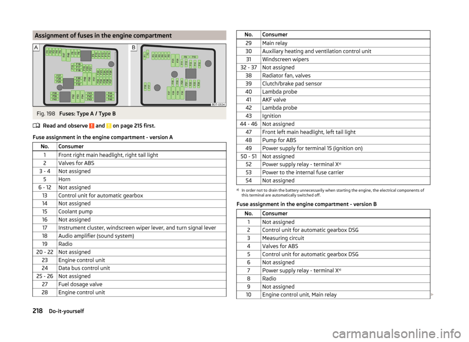
Fuse assignment in the engine compartment - version A
No.Consumer1Front right main headlight, right tail light2Valves for ABS3 - 4Not assigned5Horn6 - 12Not assigned13Control unit for automatic gearbox14Not assigned15Coolant pump16Not assigned17Instrument cluster, windscreen wiper lever, and turn signal lever18Audio amplifier (sound system)19Radio20 - 22Not assigned23Engine control unit24Data bus control unit25 - 26Not assigned27Fuel dosage valve28Engine control unitNo.Consumer29Main relay30Auxiliary heating and ventilation control unit31Windscreen wipers32 - 37Not assigned38Radiator fan, valves39Clutch/brake pad sensor40Lambda probe41AKF valve42Lambda probe43Ignition44 - 46Not assigned47Front left main headlight, left tail light48Pump for ABS49Power supply for terminal 15 (ignition on)50 - 51Not assigned52Power supply relay - terminal X a)53Power to the internal fuse carrier54Not assigneda)
In order not to drain the battery unnecessarily when starting the engine, the electrical components of
this terminal are automatically switched off.
Fuse assignment in the engine compartment - version B
No.Consumer1Not assigned2Control unit for automatic gearbox DSG3Measuring circuit4Valves for ABS5Control unit for automatic gearbox DSG6Not assigned7Power supply relay - terminal X a)8Radio9Not assigned10Engine control unit, Main relay
218Do-it-yourself
Page 221 of 246
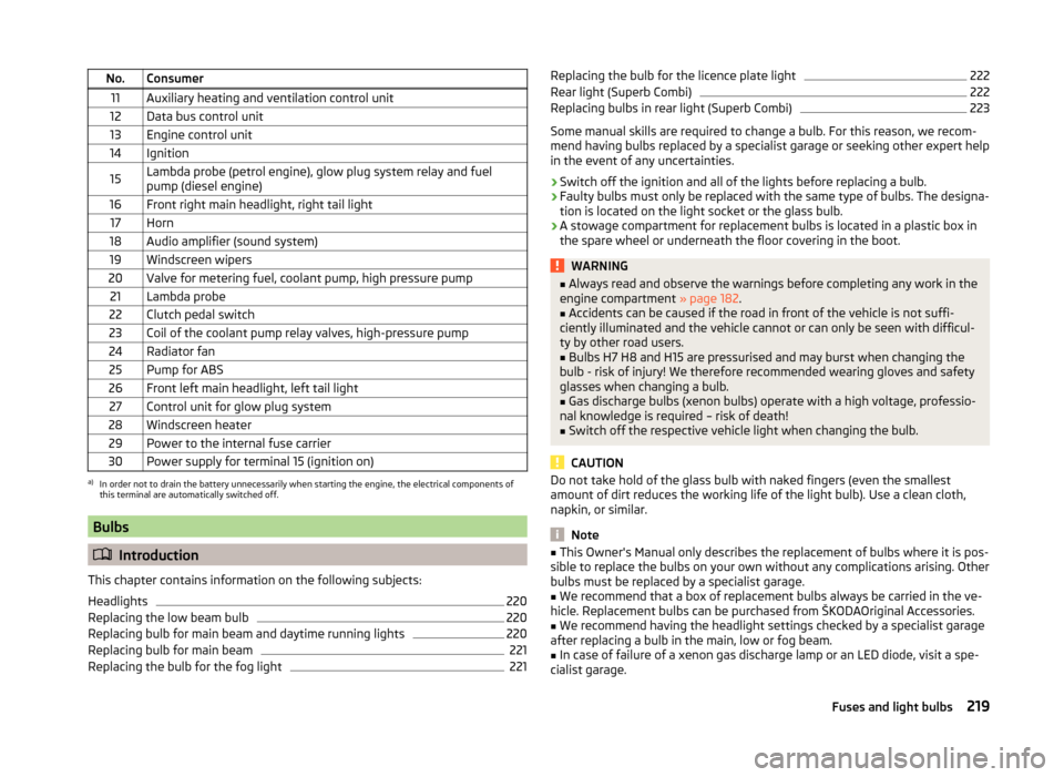
No.Consumer11Auxiliary heating and ventilation control unit12Data bus control unit13Engine control unit14Ignition15Lambda probe (petrol engine), glow plug system relay and fuel
pump (diesel engine)16Front right main headlight, right tail light17Horn18Audio amplifier (sound system)19Windscreen wipers20Valve for metering fuel, coolant pump, high pressure pump21Lambda probe22Clutch pedal switch23Coil of the coolant pump relay valves, high-pressure pump24Radiator fan25Pump for ABS26Front left main headlight, left tail light27Control unit for glow plug system28Windscreen heater29Power to the internal fuse carrier30Power supply for terminal 15 (ignition on)a)
In order not to drain the battery unnecessarily when starting the engine, the electrical components of
this terminal are automatically switched off.
Bulbs
Introduction
This chapter contains information on the following subjects:
Headlights
220
Replacing the low beam bulb
220
Replacing bulb for main beam and daytime running lights
220
Replacing bulb for main beam
221
Replacing the bulb for the fog light
221Replacing the bulb for the licence plate light222Rear light (Superb Combi)222
Replacing bulbs in rear light (Superb Combi)
223
Some manual skills are required to change a bulb. For this reason, we recom-
mend having bulbs replaced by a specialist garage or seeking other expert help
in the event of any uncertainties.
› Switch off the ignition and all of the lights before replacing a bulb.
› Faulty bulbs must only be replaced with the same type of bulbs. The designa-
tion is located on the light socket or the glass bulb.
› A stowage compartment for replacement bulbs is located in a plastic box in
the spare wheel or underneath the floor covering in the boot.
WARNING■ Always read and observe the warnings before completing any work in the
engine compartment » page 182.■
Accidents can be caused if the road in front of the vehicle is not suffi-
ciently illuminated and the vehicle cannot or can only be seen with difficul-
ty by other road users.
■
Bulbs H7 H8 and H15 are pressurised and may burst when changing the
bulb - risk of injury! We therefore recommended wearing gloves and safety
glasses when changing a bulb.
■
Gas discharge bulbs (xenon bulbs) operate with a high voltage, professio-
nal knowledge is required – risk of death!
■
Switch off the respective vehicle light when changing the bulb.
CAUTION
Do not take hold of the glass bulb with naked fingers (even the smallest
amount of dirt reduces the working life of the light bulb). Use a clean cloth,
napkin, or similar.
Note
■ This Owner's Manual only describes the replacement of bulbs where it is pos-
sible to replace the bulbs on your own without any complications arising. Other
bulbs must be replaced by a specialist garage.■
We recommend that a box of replacement bulbs always be carried in the ve-
hicle. Replacement bulbs can be purchased from ŠKODAOriginal Accessories.
■
We recommend having the headlight settings checked by a specialist garage
after replacing a bulb in the main, low or fog beam.
■
In case of failure of a xenon gas discharge lamp or an LED diode, visit a spe-
cialist garage.
219Fuses and light bulbs
Page 226 of 246
Technical data
Technical data
Vehicle data
Introduction
This chapter contains information on the following subjects:
Vehicle identification data
224
Operating weight and payload
224
Measurement of fuel consumption and CO 2 emissions according to ECE
Regulations and EU Directives
225
Dimensions
226
Vehicle-specific information depending on engine type
227
Multi-purpose vehicles (AF)
231
The details given in the vehicle's technical documentation always take prece-
dence over the details in the Owner's Manual.
The listed performance values were determined without performance-reduc- ing equipment, e.g. air conditioning system.
Vehicle identification data
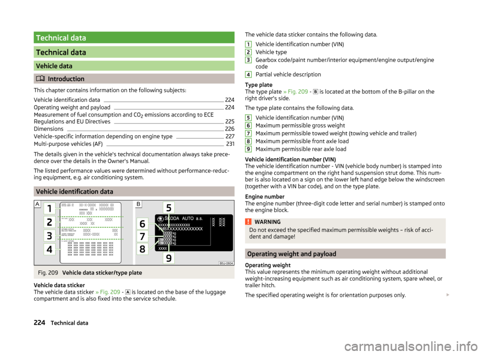
Fig. 209
Vehicle data sticker/type plate
Vehicle data sticker
The vehicle data sticker » Fig. 209 -
is located on the base of the luggage
compartment and is also fixed into the service schedule.
The vehicle data sticker contains the following data.
Vehicle identification number (VIN)
Vehicle type
Gearbox code/paint number/interior equipment/engine output/engine
code
Partial vehicle description
Type plate
The type plate » Fig. 209 -
is located at the bottom of the B-pillar on the
right driver's side.
The type plate contains the following data. Vehicle identification number (VIN)
Maximum permissible gross weight
Maximum permissible towed weight (towing vehicle and trailer)
Maximum permissible front axle load
Maximum permissible rear axle load
Vehicle identification number (VIN)
The vehicle identification number - VIN (vehicle body number) is stamped into
the engine compartment on the right hand suspension strut dome. This num-
ber is also located on a sign on the lower left hand edge below the windscreen
(together with a VIN bar code), and on the type plate.
Engine number
The engine number (three-digit code letter and serial number) is stamped onto
the engine block.WARNINGDo not exceed the specified maximum permissible weights – risk of acci-
dent and damage!
Operating weight and payload
Operating weight
This value represents the minimum operating weight without additional
weight-increasing equipment such as air conditioning system, spare wheel, or
trailer hitch.
The specified operating weight is for orientation purposes only.
123456789224Technical data
Page 227 of 246
The operating weight also contains the weight of the driver (75 kg), the weight
of the operating fluids, the tool kit, and a fuel tank filled to 90 % capacity.
Operating weight of the vehicle » page 227, Vehicle-specific information de-
pending on engine type .
Payload
It is possible to calculate the approximate maximum payload from the differ-
ence between the permissible total weight and the operating weight.
The payload consists of the following weights.
› The weight of the passengers.
› The weight of all items of luggage and other loads.
› The weight of the roof, including the roof rack system.
› The weight of the equipment that is excluded from the operating weight.
› Trailer drawbar load when towing a trailer (max. 80 kg).
Note
If required, you can find out the precise weight of your vehicle at a specialist
garage.
Measurement of fuel consumption and CO 2 emissions according to
ECE Regulations and EU Directives
The data on fuel consumption and CO 2 emissions were not available at the
time of going to press.
The data on fuel consumption and CO 2 emissions are given on the ŠKODA
websites or in the sales and technical vehicle documentation.
The measurement of the intra-urban cycle begins with a cold start of the en-
gine. Afterwards urban driving is simulated.
In the extra-urban driving cycle, the vehicle is accelerated and decelerated in
all gears, corresponding to daily routine driving conditions. The driving speed
varies between 0 and 120 km/h.
The calculation of the combined fuel consumption considers a weighting of
about 37 % for the intra-urban cycle and 63 % for the extra-urban cycle.
Note■ The fuel consumption and emission levels given on the ŠKODA websites or in
the commercial and technical vehicle documentation have been established in
accordance with rules and under conditions that are set out by legal or techni-
cal rules for the determination of operational and technical data of motor vehi-
cles.■
Depending on the extent of the equipment, the driving style, traffic condi-
tions, weather influences and vehicle condition, consumption values can in
practice result in fuel economy figures in the use of the vehicle that differ from
the fuel consumption values listed on the ŠKODA websites or in the commer-
cial and technical vehicle documentation.
225Technical data