coolant SKODA SUPERB 2015 3.G / (B8/3V) User Guide
[x] Cancel search | Manufacturer: SKODA, Model Year: 2015, Model line: SUPERB, Model: SKODA SUPERB 2015 3.G / (B8/3V)Pages: 276, PDF Size: 42.14 MB
Page 126 of 276
WARNING■The auxiliary heating (auxiliary heating and ventilation) (following as aux.
heating) must never be operated in closed rooms (e.g. garages) – risk of
poisoning!■
The auxiliary heating must not be allowed to run during refuelling – risk
of fire.
■
The exhaust pipe of the auxiliary heating is located on the underside of
the vehicle. If you want to use the heater, do not switch off the car in pla-
ces where the exhaust fumes can come into contact with flammable mate-
rials such as dry grass, undergrowth, leaves, spilled fuel etc. -. risk of fire.
CAUTION
■ The exhaust pipe of the auxiliary heating, which is located on the underside
of the vehicle, must not be clogged and the exhaust flow must not be blocked.■
If the auxiliary heating is running, the vehicle battery discharges.
■
The air inlet in front of the windscreen must be free (e.g. of ice, snow or
leaves) to ensure that the auxiliary heating operates properly.
Note
■ The auxiliary heating only switches the blower on, if it has achieved a coolant
temperature of approx. 50 °C.■
At low outside temperatures, this can result in a formation of water vapour in
the area of the engine compartment. This is quite normal and is not an operat-
ing problem.
■
So that warm air can flow into the vehicle interior after switching on the aux.
heating, you must maintain the comfort temperature normally selected by you,
leave the fan switched on and leave the air outlet vents in open. It is recom-
mended to put the air flow in the position
or
.
Switching on/offFig. 159
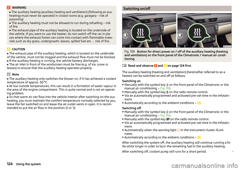
Button for direct power on / off of the auxiliary heating (heating
and ventilation) on the front panel of the Climatronic / manual air condi-
tioning
Read and observe
and on page 124 first.
The auxiliary heating (heating and ventilation) (hereinafter referred to as a
heater) can be switched on and off as follows.
Switching on
▶ Manually with the symbol key on the front panel of the Climatronic or the
manual air conditioning » Fig. 159.
▶ Manually with the symbol key on the radio remote control.
▶ Via an automatically programmed and activated pre-set time in the Infotain-
ment.
▶ Automatically according to the ambient conditions »
.
Switching off
▶ Manually with the symbol key on the front panel of the Climatronic or the
manual air conditioning » Fig. 159.
▶ Manually with the symbol key on the radio remote control.
▶ Via an automatically programmed and activated pre-set time in the Infotain-
ment.
▶ Automatically when the warning light in the instrument cluster illumi-
nates.
▶ Automatically according to the ambient conditions »
.
After switching the system off, the auxiliary heating will continue running a lit-
tle while longer in order to burn the remaining fuel in the auxiliary heating.
After switching off, coolant pump still runs for a short period.
124Using the system
Page 192 of 276

General Maintenance
Care and maintenance
Service work, adjustments and technical alterations
Introduction
This chapter contains information on the following subjects:
Vehicle operating under different weather conditions
190
Statutory checks
190
ŠKODA Service Partners
191
ŠKODA Original parts
191
ŠKODA Original accessories
191
Spoiler
192
Component protection
192
Airbags
192
Acceptance and recycling of used vehicles
193
The instructions and guidelines from ŠKODA AUTO a.s. must be observed when
carrying out any modifications, repairs or technical alterations to your vehicle.
Adhering to these instructions and guidelines helps ensure road safety and
helps keep your vehicle in a good technical condition. After carrying out modifi-
cations, repairs or technical alterations, the vehicle will comply with German
road transport regulations (StVZO).
Always consult a ŠKODA Partner » page 191 before buying accessories or
parts, or before carrying out any modifications, repairs or technical alterations
to your vehicle.
WARNING■ Work on your vehicle, which have been carried out unprofessionally, can
cause operational faults – risk of accident!■
Interference on the electronic components and their software can lead to
operational faults. This interference can also impair not directly affected
systems because of the networking of the electronic components. The op-
erational safety of the vehicle may be at significant risk and can lead to in-
creased wear of parts.
For the sake of the environmentTechnical documents regarding alterations carried out on the vehicle must be
kept by the vehicle user in order to be handed over to the recyclers at a later
date. This ensures that the vehicle is recycled in an environmentally sound
manner.
Note
■ We recommend only having these modifications, repairs and technical
changes performed by a specialist garage.■
Any damage caused by technical alterations made without the approval of
the manufacturer is excluded from the warranty » Service schedule .
■
The ŠKODA Partner accepts no liability for products that have not been ap-
proved by ŠKODA AUTO a.s. even though these may be products with an op-
erational approval or that have been approved by a government testing insti-
tute.
■
We advise you only to use ŠKODA Original Accessories and ŠKODA Original
Parts which have been expressly approved for use on your vehicle. Reliability,
safety and suitability for your vehicle are guaranteed with these.
■
ŠKODA Original Accessories and ŠKODA Original Parts can be purchased from
ŠKODA Partners, who will also perform the professional assembly of the pur-
chased parts.
Vehicle operating under different weather conditions
Read and observe
on page 190 first.
If you would like to operate your vehicle in countries other than those with itsintended weather conditions, you should contact a ŠKODA Partner.
She will advise you if certain precautions need to be taken to ensure the full
functioning of the vehicle and to prevent damage.
This involves, for example, the coolant, battery replacement and the like.
Statutory checks
Read and observe
on page 190 first.
Many countries have legislation requiring the operational reliability and roadworthiness and/or exhaust gas properties of a vehicle to be tested at specific
intervals. These tests can be carried out by workshops or testing stations that
have been legally authorized for this purpose.
190General Maintenance
Page 208 of 276
After refilling›After refilling AdBlue®
put the cap on the fuel filler neck and turn in the oppo-
site direction of the arrow 3
until it engages.
›
Close the fuel filler flap until it clicks into place.
Before driving
›
After filling AdBlue ®
only switch on the ignition and leave it on for at least 30
s, so that the refilling can be recognized by the system.
Only then start the engine.
CAUTION
The AdBlue ®
- tank is full when no AdBlue ®
flows from the refill bottle or as
soon as the correctly operated pump cuts out for the first time. Do not contin-
ue refilling AdBlue ®
.
Note
The working life of the AdBlue ®
solution is 4 years. Thereafter the solution
must be replaced by a specialist garage.
Engine compartment
Introduction
This chapter contains information on the following subjects:
Opening and closing the bonnet
207
Engine compartment overview
208
Radiator fan
208
Windscreen washer system
208WARNINGInjuries or scolding or risks of accident or fire may occur when working in
the engine compartment. For this reason, it is essential to comply with the
warning instructions outlined below and with the general applicable safety
rules. The engine compartment of your car is a hazardous area!WARNINGInstructions before beginning work in the engine compartment■Turn off the engine and remove the ignition key.■
The parking brake switch.
WARNING (Continued)■ For vehicles with manual transmission the lever into the neutral position.■On vehicles with automatic transmission, shift the selector lever into the
P position.■
Allow the engine to cool.
■
Never open the bonnet if you can see steam or coolant escaping from the
engine compartment – risk of scalding! Wait until no more steam or coolant
is escaping.
WARNINGInformation for working in the engine room■Keep all people, especially children, away from the engine compartment.■
Never touch the radiator fan. The fan might suddenly start running!
■
Do not touch any hot engine parts – risk of burns!
WARNINGInformation for working in the engine compartment with the engine run-
ning■
Pay particular attention to moving engine parts, e.g. V-ribbed belt, gener-
ator, radiator fan - danger to life!
■
Never touch the electric wiring on the ignition system.
■
Avoid short circuits in the electrical system, particularly on the vehicle's
battery.
■
Always make sure that no jewellery, loose clothing or long hair can get
caught in rotating engine parts – risk to life! Always remove any jewellery,
tie back long hair and wear tight fitting clothing before completing any
work.
WARNINGInformation for working on the fuel system or the electrical system■Always disconnect the vehicle battery from the electrical system.■
Do not smoke.
■
Never work near open flames.
■
Always have a functioning fire extinguisher nearby.
206General Maintenance
Page 210 of 276
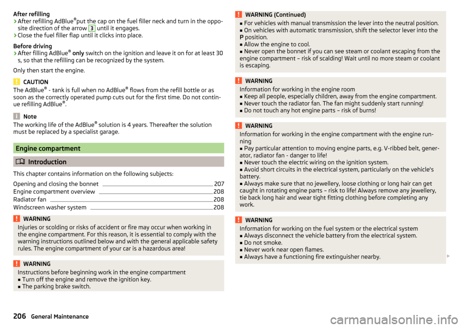
Engine compartment overviewFig. 228
Principle sketch: Engine compartment
Read and observe
and on page 206 first.
Layout of the engine compartment » Fig. 228
Coolant expansion reservoir
211
Engine oil dipstick
210
Engine oil filler opening
210
Brake fluid reservoir
212
Battery (under a cover)
213
Windscreen washer fluid reservoir
208
Note
The location of the inspection points in the engine compartment of petrol and
diesel engines is practically identical.
Radiator fan
Read and observe
and on page 206 first.
The radiator fan is powered by an electric motor. Operation is controlled ac-
cording to the temperature of the coolant.
WARNINGAfter switching off the ignition, the fan may intermittently continue to op-
erate for approx. 10 minutes.ABCDEFWindscreen washer systemFig. 229
Windscreen washer fluid reservoir
Read and observe
and on page 206 first.
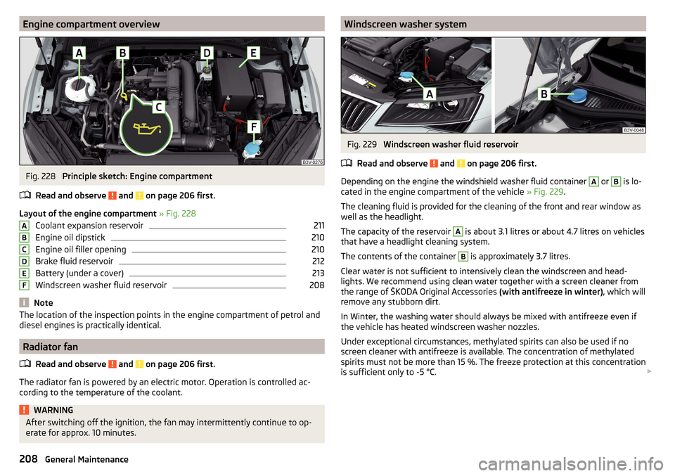
Depending on the engine the windshield washer fluid container
A
or
B
is lo-
cated in the engine compartment of the vehicle » Fig. 229.
The cleaning fluid is provided for the cleaning of the front and rear window as
well as the headlight.
The capacity of the reservoir
A
is about 3.1 litres or about 4.7 litres on vehicles
that have a headlight cleaning system.
The contents of the container
B
is approximately 3.7 litres.
Clear water is not sufficient to intensively clean the windscreen and head-
lights. We recommend using clean water together with a screen cleaner from
the range of ŠKODA Original Accessories (with antifreeze in winter), which will
remove any stubborn dirt.
In Winter, the washing water should always be mixed with antifreeze even if
the vehicle has heated windscreen washer nozzles.
Under exceptional circumstances, methylated spirits can also be used if no
screen cleaner with antifreeze is available. The concentration of methylated
spirits must not be more than 15 %. The freeze protection at this concentration
is sufficient only to -5 °C.
208General Maintenance
Page 212 of 276
CAUTION■In an emergency, another engine oil to be refilled. To prevent damage to the
engine, a maximum of 0.5 litres only of the following engine oils may be used:
■ For petrol engine models: ACEA A3/ACEA B4 or API SN, (API SM);
■ For diesel engine models: ACEA C3 or API CJ-4.
Checking the oil level
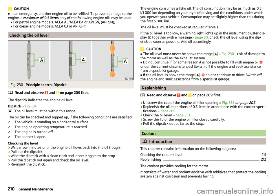
Fig. 230
Principle sketch: Dipstick
Read and observe
and on page 209 first.
The dipstick indicates the engine oil level .
Dipstick » Fig. 230
The oil level must be within this range.
The oil can be checked and topped up, if the following conditions are satisfied. The vehicle is standing on a horizontal surface.
The engine operating temperature is reached.
The engine is turned off.
The bonnet is open.
Checking the level
›
Wait a few minutes until the engine oil flows back into the oil trough.
›
Pull out the dipstick.
›
Wipe the dipstick with a clean cloth and insert it again to the stop.
›
Pull the dipstick out again and check the oil level.
›
Re-insert the dipstick.
AThe engine consumes a little oil. The oil consumption may be as much as 0.5
l/1 000 km depending on your style of driving and the conditions under which
you operate your vehicle. Consumption may be slightly higher than this during
the first 5 000 km.
The oil level must be checked at regular intervals.
If the oil level is too low, a warning light lights up in the instrument cluster dis-
play
together with a message » page 38. Check the oil level using the dip-
stick as soon as possible. Add oil accordingly.
CAUTION
■ The oil level must never be above the range A » Fig. 230 - risk of damage to
the motor as well as the exhaust system.■
Do not continue if for some reason it is not possible to fill with engine oil
under the current circumstances! Switch off the engine and seek assistance
from a specialist garage.
■
If the oil level is above the range
A
,
do not continue to drive! Switch off
the engine and seek assistance from a specialist garage.
Replenishing
Read and observe
and on page 209 first.
›
Unscrew the cap of the engine oil filler opening » Fig. 228 on page 208 .
›
Replenish the oil in portions of 0.5 litres in accordance with the correct speci-
fications » page 209 .
›
Check the oil level » page 210.
›
Screw the lid of the engine oil filler closed carefully.
›
Pull the dipstick out as far as the stop.
Coolant
Introduction
This chapter contains information on the following subjects:
Checking the coolant level
211
Replenishing
212
The coolant provides cooling for the motor.
It consists of water and coolant additive with additives that protect the cooling
system against corrosion and prevents furring.
210General Maintenance
Page 213 of 276

The proportion of coolant additive in the mixture must be at least 40%.
The coolant additive may be increased to a maximum of 60%.
The correct mixing ratio of water and coolant additive is to be checked if nec-
essary by a specialist garage or is to be restored if necessary.
The description of the coolant is shown in the coolant expansion reservoir
» Fig. 231 on page 211 .WARNINGThe engine compartment of your car is a hazardous area. The following
warning instructions must be followed at all times when working in the en- gine compartment » page 206.■
The coolant is harmful to health.
■
Avoid contact with the coolant.
■
Coolant vapours are harmful to health.
■
Never open the end cover of the coolant expansion reservoir while the
engine is still warm. The cooling system is pressurized!
■
When opening the end cover of the coolant expansion reservoir, cover it
with a cloth to protect your face, hands and arms from hot steam or hot
coolant.
■
If any coolant splashes into your eyes, immediately rinse out your eyes
with clear water and contact a doctor as soon as possible.
■
Always keep the coolant in the original container, safe from people who
are not completely independent, especially children - there is a danger of
poisoning!
■
If coolant is swallowed, consult a doctor immediately.
■
Never spill operating fluids over the hot engine - risk of fire.
CAUTION
■ Do not continue if for some reason it is not possible to fill with coolant un-
der the current circumstances! Switch off the engine and seek assistance from
a specialist garage.■
If the expansion tank is empty, do not top up with coolant. The system could
ventilate - there is a risk of engine damage,
not continue! Switch off the en-
gine and seek assistance from a specialist garage.
■
The concentration of coolant additive in the coolant must never be under
40%.
■
Over 60% of coolant additive in the coolant reduces the antifreeze protec-
tion and cooling effect.
■
A coolant additive that does not comply with the correct specification can
significantly reduce the corrosion protection of the cooling system.
■ Any faults resulting from corrosion may cause a loss of coolant and can con-
sequently result in major engine damage.■
Do not fill the coolant above the mark
A
» Fig. 231 on page 211 .
■
If an error occurs, leading to the engine overheating, the help of a professio-
nal garage is to be sought - there is a risk of serious engine damage occurring.
■
Additional headlights and other attached components in front of the air inlet
impair the cooling efficiency of the coolant.
■
Never cover the radiator - there is a risk of the engine overheating.
Note
The coolant capacity is approximately 1 l greater on vehicles that are fitted
with an auxiliary heater (auxiliary heating and ventilation).
Checking the coolant level
Fig. 231
Coolant expansion reservoir
Read and observe and on page 211 first.
The coolant expansion bottle is located in the engine compartment.
Coolant expansion reservoir » Fig. 231
Mark for the maximum permissible coolant level
Mark for the lowest permissible coolant level
The coolant level should be kept between the marks
A
and
B
.
The coolant can be checked and topped up, if the following conditions are sat-
isfied.
The vehicle is standing on a horizontal surface.
The engine is turned off.
The engine is not heated.
The bonnet is open.
AB211Inspecting and replenishing
Page 214 of 276
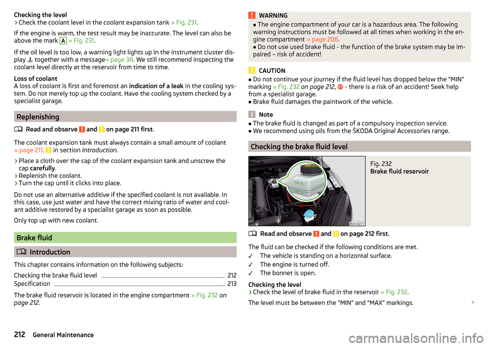
Checking the level›Check the coolant level in the coolant expansion tank » Fig. 231.
If the engine is warm, the test result may be inaccurate. The level can also be
above the mark A
» Fig. 231 .
If the oil level is too low, a warning light lights up in the instrument cluster dis-
play
together with a message » page 38. We still recommend inspecting the
coolant level directly at the reservoir from time to time.
Loss of coolant
A loss of coolant is first and foremost an indication of a leak in the cooling sys-
tem. Do not merely top up the coolant. Have the cooling system checked by a
specialist garage.
Replenishing
Read and observe
and on page 211 first.
The coolant expansion tank must always contain a small amount of coolant» page 211, in section Introduction .
›
Place a cloth over the cap of the coolant expansion tank and unscrew the
cap carefully .
›
Replenish the coolant.
›
Turn the cap until it clicks into place.
Do not use an alternative additive if the specified coolant is not available. In
this case, use just water and have the correct mixing ratio of water and cool-
ant additive restored by a specialist garage as soon as possible.
Only top up with new coolant.
Brake fluid
Introduction
This chapter contains information on the following subjects:
Checking the brake fluid level
212
Specification
213
The brake fluid reservoir is located in the engine compartment » Fig. 232 on
page 212 .
WARNING■
The engine compartment of your car is a hazardous area. The following
warning instructions must be followed at all times when working in the en-
gine compartment » page 206.■
Do not use used brake fluid - the function of the brake system may be im-
paired – risk of accident!
CAUTION
■ Do not continue your journey if the fluid level has dropped below the “MIN”
marking » Fig. 232 on page 212 , - there is a risk of an accident! Seek help
from a specialist garage.■
Brake fluid damages the paintwork of the vehicle.
Note
■ The brake fluid is changed as part of a compulsory inspection service.■We recommend using oils from the ŠKODA Original Accessories range.
Checking the brake fluid level
Fig. 232
Brake fluid reservoir
Read and observe and on page 212 first.
The fluid can be checked if the following conditions are met.
The vehicle is standing on a horizontal surface.
The engine is turned off.
The bonnet is open.
Checking the level
›
Check the level of brake fluid in the reservoir » Fig. 232.
The level must be between the “MIN” and “MAX” markings.
212General Maintenance
Page 243 of 276
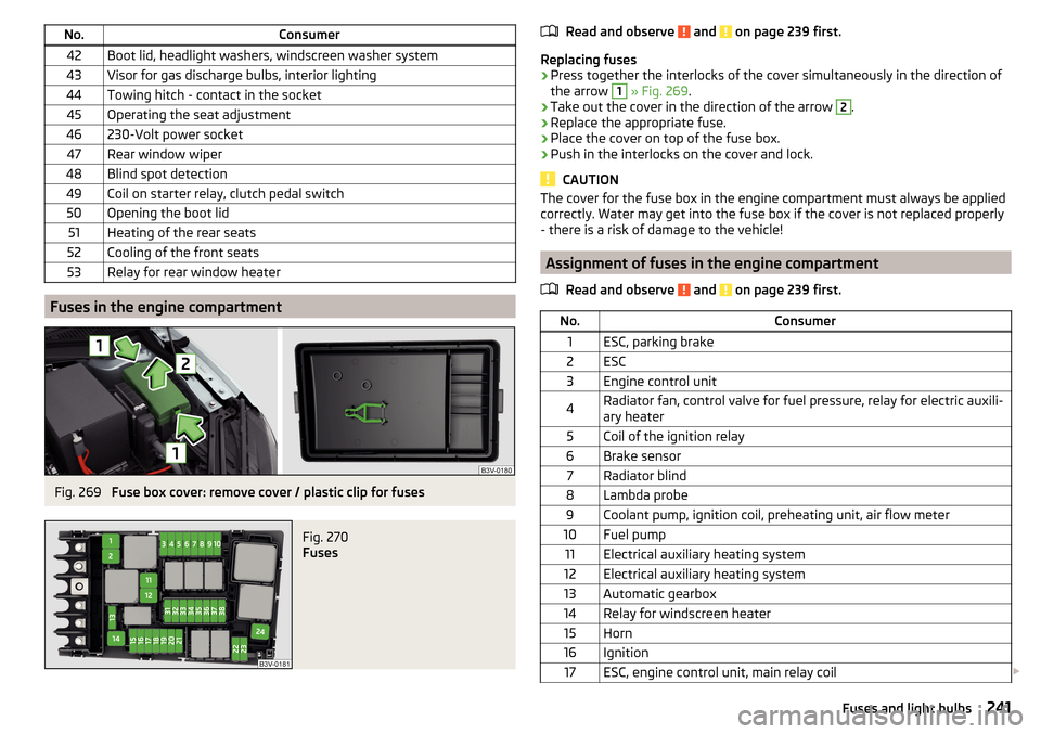
No.Consumer42Boot lid, headlight washers, windscreen washer system43Visor for gas discharge bulbs, interior lighting44Towing hitch - contact in the socket45Operating the seat adjustment46230-Volt power socket47Rear window wiper48Blind spot detection49Coil on starter relay, clutch pedal switch50Opening the boot lid51Heating of the rear seats52Cooling of the front seats53Relay for rear window heater
Fuses in the engine compartment
Fig. 269
Fuse box cover: remove cover / plastic clip for fuses
Fig. 270
Fuses
Read and observe and on page 239 first.
Replacing fuses
›
Press together the interlocks of the cover simultaneously in the direction of
the arrow
1
» Fig. 269 .
›
Take out the cover in the direction of the arrow
2
.
›
Replace the appropriate fuse.
›
Place the cover on top of the fuse box.
›
Push in the interlocks on the cover and lock.
CAUTION
The cover for the fuse box in the engine compartment must always be applied
correctly. Water may get into the fuse box if the cover is not replaced properly
- there is a risk of damage to the vehicle!
Assignment of fuses in the engine compartment
Read and observe
and on page 239 first.
No.Consumer1ESC, parking brake2ESC3Engine control unit4Radiator fan, control valve for fuel pressure, relay for electric auxili-
ary heater5Coil of the ignition relay6Brake sensor7Radiator blind8Lambda probe9Coolant pump, ignition coil, preheating unit, air flow meter10Fuel pump11Electrical auxiliary heating system12Electrical auxiliary heating system13Automatic gearbox14Relay for windscreen heater15Horn16Ignition17ESC, engine control unit, main relay coil 241Fuses and light bulbs
Page 259 of 276
automatic transmissionselector lever lock defect137
Automatic transmission135
Kick down138
Launch control138
Malfunctions37
Selector lever lock137
Warning light37
Warning messages37
AUX99
Auxiliary heating (auxiliary heating and ventila- tion)
123
Adjust124
Switching on/off124
Auxiliary heating (heating and ventilation) Radio remote control
125
Avoiding damage to your vehicle141
B
Bags on the backs of the front seats
97
on the inner sides of the front seats97
Battery In the remote control key
234
Replace the KESSY key234
Belts11
Belt tensioners14
Bonnet Closing
207
Opening207
Boot Class N1 vehicles
114
Non-contact opening61
See Boot lid59
Boot lid automatic locking
59
Closing59
Non-contact opening61
Opening59
Brake Information messages33
Warning light33
Brake Assist (HBA)145
Brake booster133
brake fluid specification
213
Brake fluid212
Checking212
Information messages33
Brake linings Warning light
36
Brake pedal (automatic transmission) Warning light
37
Brakes Brake booster
133
Brake fluid212
Braking and stabilisation systems143
Running-in139
Brakes and parking132
Brake system143
Braking Information on braking
132
Bulbs Replacing
242
C
Camera Lens care
197
Camera lens care
197
Car care Jack
197
Car computer see multifunction display
42
Care and maintenance190
Cargo element112
Car park134
Car park ticket holder91
Carrier Roof rack117
Cavity protection197
Central locking52
Problems57
Central locking button55
Change Bulb for indicator (halogen headlight)
243
engine oil209
light bulb in tail light244
Change engine oil
209
Changing Wheels
224
Changing a wheel Follow-up tasks
227
Preparation224
Changing wheels Wheel removal and fix
227
Charging a vehicle battery215
Checking Battery electrolyte level
214
Brake fluid212
Coolant211
Engine oil210
Oil level210
Windscreen washer fluid208
Checks Statutory checks
190
Children and safety20
Child safety Side airbag
22
Child safety lock57
Child safety seat Use of child safety seats
23
Child seat Classification
22
i-Size25
ISOFIX23
on the front passenger seat21
257Index
Page 260 of 276

TOP TETHER25
Use of child safety seats i-Size25
Use of ISOFIX child seats24
Chrome parts Refer to vehicle maintenance
196
Cigarette lighter102
Clean Anodized parts
196
Chrome parts196
Cleaning Alcantara
199
and maintaining belts200
artificial leather199
headlight glasses197
materials199
natural leather199
plastic parts196
seats covers of the electrically heated seats200
wheels197
Cleaning safety belt
200
Cleaning seat covers
200
Cleaning the interior artificial leather
199
Seat covers200
Cleaning the vehicle exterior Camera lens
197
Cavity protection197
Decorative films195
Door locking cylinder197
Headlight glasses197
Protective films195
Under-body protection198
wheels197
Windows and external mirrors196
Cleaning vehicle193
Cleaning vehicle exterior194
Anodized parts196
Chrome parts196
Plastic parts196
Rubber seals196
Vehicle paint work195
Wiper blades198
Clean interior Safety belt
200
Climatronic air distribution control
122
Automatic operation121
Operating elements120
Clothes hook96
Cockpit 12 volt power outlet
100
Ashtray103
Cigarette lighter102
General view27
Lighting74
storage compartments90
useful equipment90
Comfort operation Window
63
COMING HOME71
compartments90
Component protection192
Components of the puncture repair kits228
Computer see multifunction display
42
Convenience operation sliding / tilting roof
65
convenience turn signal68
Coolant210
Checking211
Information messages38
Replenishing212
Temperature gauge30
Warning light38
CORNER see Headlights with CORNER function
71
Correct routing of seat belt
12
Correct seated position8
Front passenger10
Rear seats10
Correct seat position Driver
9
Counter for distance driven31
Crew Protect Assist173
cruise control operation
160
operation description161
Cruise Control System160
Cup holders92
D
DAY LIGHT see Daylight running lights
68
Daylight running lights68
DCC171
Warning light41
De-icing windows
196
De-icing the windscreen and rear window75
Deactivating an airbag19
Decorative films195
Delayed locking of the boot lid see boot lid
59
Diesel refer to Fuel
203
Diesel fuel Operation in winter
203
Diesel particulate filter39
information messages39
Digital Clock31
Dipstick210
Disconnecting and reconnecting vehicle battery
215
Display29
Compass points48
Coolant temperature30
258Index