remote control SKODA SUPERB 2015 3.G / (B8/3V) User Guide
[x] Cancel search | Manufacturer: SKODA, Model Year: 2015, Model line: SUPERB, Model: SKODA SUPERB 2015 3.G / (B8/3V)Pages: 276, PDF Size: 42.14 MB
Page 125 of 276
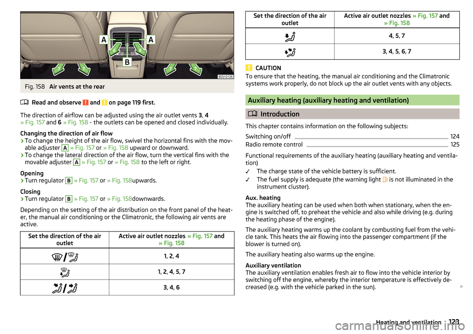
Fig. 158
Air vents at the rear
Read and observe
and on page 119 first.
The direction of airflow can be adjusted using the air outlet vents 3, 4
» Fig. 157 and 6 » Fig. 158 - the outlets can be opened and closed individually.
Changing the direction of air flow
›
To change the height of the air flow, swivel the horizontal fins with the mov-
able adjuster
A
» Fig. 157 or » Fig. 158 upward or downward.
›
To change the lateral direction of the air flow, turn the vertical fins with the
movable adjuster
A
» Fig. 157 or » Fig. 158 to the left or right.
Opening
›
Turn regulator
B
» Fig. 157 or » Fig. 158 upwards.
Closing
›
Turn regulator
B
» Fig. 157 or » Fig. 158 downwards.
Depending on the setting of the air distribution on the front panel of the heat-
er, the manual air conditioning or the Climatronic, the following air vents are
active.
Set the direction of the air outletActive air outlet nozzles » Fig. 157 and
» Fig. 158 1, 2 , 41, 2 , 4 , 5 , 7 3, 4 , 6Set the direction of the air
outletActive air outlet nozzles » Fig. 157 and
» Fig. 1584 , 5 , 73 , 4 , 5 , 6 , 7
CAUTION
To ensure that the heating, the manual air conditioning and the Climatronic
systems work properly, do not block up the air outlet vents with any objects.
Auxiliary heating (auxiliary heating and ventilation)
Introduction
This chapter contains information on the following subjects:
Switching on/off
124
Radio remote control
125
Functional requirements of the auxiliary heating (auxiliary heating and ventila-
tion)
The charge state of the vehicle battery is sufficient.
The fuel supply is adequate (the warning light is not illuminated in the
instrument cluster).
Aux. heating
The auxiliary heating can be used when both when stationary, when the en-
gine is switched off, to preheat the vehicle and also while driving (e.g. during
the heating phase of the engine).
The auxiliary heating warms up the coolant by combusting fuel from the vehi-
cle tank. This heats the air flowing into the passenger compartment (if the
blower is turned on).
The auxiliary heating also warms up the engine.
Auxiliary ventilation
The auxiliary ventilation enables fresh air to flow into the vehicle interior by
switching off the engine, whereby the interior temperature is effectively de-
creased (e.g. with the vehicle parked in the sun).
123Heating and ventilation
Page 126 of 276
WARNING■The auxiliary heating (auxiliary heating and ventilation) (following as aux.
heating) must never be operated in closed rooms (e.g. garages) – risk of
poisoning!■
The auxiliary heating must not be allowed to run during refuelling – risk
of fire.
■
The exhaust pipe of the auxiliary heating is located on the underside of
the vehicle. If you want to use the heater, do not switch off the car in pla-
ces where the exhaust fumes can come into contact with flammable mate-
rials such as dry grass, undergrowth, leaves, spilled fuel etc. -. risk of fire.
CAUTION
■ The exhaust pipe of the auxiliary heating, which is located on the underside
of the vehicle, must not be clogged and the exhaust flow must not be blocked.■
If the auxiliary heating is running, the vehicle battery discharges.
■
The air inlet in front of the windscreen must be free (e.g. of ice, snow or
leaves) to ensure that the auxiliary heating operates properly.
Note
■ The auxiliary heating only switches the blower on, if it has achieved a coolant
temperature of approx. 50 °C.■
At low outside temperatures, this can result in a formation of water vapour in
the area of the engine compartment. This is quite normal and is not an operat-
ing problem.
■
So that warm air can flow into the vehicle interior after switching on the aux.
heating, you must maintain the comfort temperature normally selected by you,
leave the fan switched on and leave the air outlet vents in open. It is recom-
mended to put the air flow in the position
or
.
Switching on/offFig. 159
Button for direct power on / off of the auxiliary heating (heating
and ventilation) on the front panel of the Climatronic / manual air condi-
tioning
Read and observe
and on page 124 first.
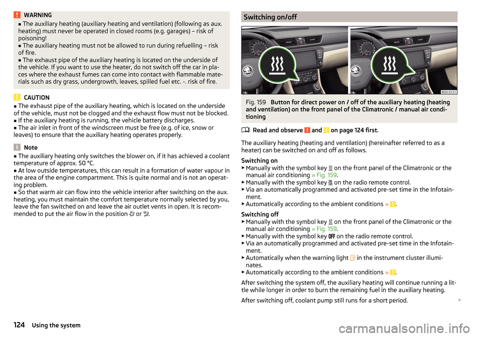
The auxiliary heating (heating and ventilation) (hereinafter referred to as a
heater) can be switched on and off as follows.
Switching on
▶ Manually with the symbol key on the front panel of the Climatronic or the
manual air conditioning » Fig. 159.
▶ Manually with the symbol key on the radio remote control.
▶ Via an automatically programmed and activated pre-set time in the Infotain-
ment.
▶ Automatically according to the ambient conditions »
.
Switching off
▶ Manually with the symbol key on the front panel of the Climatronic or the
manual air conditioning » Fig. 159.
▶ Manually with the symbol key on the radio remote control.
▶ Via an automatically programmed and activated pre-set time in the Infotain-
ment.
▶ Automatically when the warning light in the instrument cluster illumi-
nates.
▶ Automatically according to the ambient conditions »
.
After switching the system off, the auxiliary heating will continue running a lit-
tle while longer in order to burn the remaining fuel in the auxiliary heating.
After switching off, coolant pump still runs for a short period.
124Using the system
Page 127 of 276
Programming the auxiliary heating in the Infotainment
For vehicles with Climatronic: on the front panel of the Climatronic button
→
Press
For vehicles with manual air conditioning: button in the Infotainment fea-
ture
→
Press
When automatic switching on is activated, the indicator light in the symbol key
lights up » Fig. 159 for about 10 seconds after the ignition is turned off.
CAUTION
The automatic switching on and off the heating for rapid heating of the vehicle
interior can be disabled in the Infotainment » Owner´s Manual Infotainment ,
chapter Setting the heating and the cooling system .
Radio remote control
Fig. 160
Radio remote control
Read and observe and on page 124 first.
Using the radio remote control, the auxiliary heating and ventilation (herein-
after referred to as auxiliary heater) can be switched on or off.
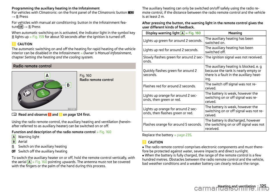
Function and description of the radio remote control » Fig. 160
Warning light
Aerial
Switch on the auxiliary heating
Switch off the auxiliary heating
To switch the auxiliary heater on or off, hold the remote control vertically, with
the aerial
A
» Fig. 160 pointing upwards. The antenna must not be covered
with the fingers or the palm of the hand during this process.
ABThe auxiliary heating can only be switched on/off safely using the radio re-
mote control, if the distance between the radio remote control and the vehicle
is at least 2 m.
After pressing the button, the warning light in the remote control gives the
user different kinds of feedback.Display warning light A » Fig. 160MeaningLights up green for around 2 seconds.The auxiliary heating has been
switched on.Lights up red for around 2 seconds.The auxiliary heating has been
switched off.Slowly flashes green for around 2 sec-
onds.The ignition signal was not received.Quickly flashes green for around 2
seconds.The auxiliary heating is blocked, e. g
because the tank is nearly empty or
there is a fault in the auxiliary heat-
ing.Flashes red for around 2 seconds.The switch off signal was not re-
ceived.Lights up orange for around 2 sec-
onds, then green or red.The battery is weak, however the
switching on or off signal was re-
ceived.Lights up orange for around 2 sec-
onds, then flashes green or red.The battery is weak, however the
switching on or off signal was not re-
ceived.Flashes orange for around 5 seconds.The battery is discharged, however
the switching on or off signal was not
received.
Replace the battery » page 235.
CAUTION
■
The radio remote control comprises electronic components and must there-
fore be protected against water, severe impacts and direct sunlight.■
When the battery is fully charged, the range of the remote control is a few
hundred metres. Obstacles between the radio remote control and the vehicle,
bad weather conditions and a weaker battery can clearly reduce the range.
125Heating and ventilation
Page 235 of 276
Removing/installing the towing eye›Manually screw the towing eye as far as it will go in the direction of the ar-
row 3
» Fig. 252 » .
For tightening purposes, we recommend, for example, using the wheel
wrench, towing eye from another vehicle or a similar object that can be pushed through the eye.
›
Unscrew the towing eye against the direction of the arrow
3
.
WARNINGThe towing eye must always be screwed in fully and firmly tightened, oth-
erwise the towing eye can tear when towing in or tow-starting.
Rear towing eye
Fig. 253
Removing the cap / fitting the towing eye
Read and observe
and on page 232 first.
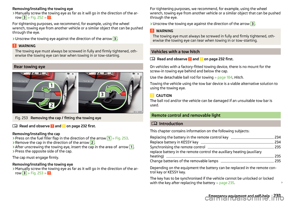
Removing/installing the cap
›
Press on the fuel filler flap in the direction of the arrow
1
» Fig. 253 .
›
Remove the cap in the direction of the arrow
2
.
›
After unscrewing the towing eye, insert the cap in the area of arrow
1
.
›
Press the opposite side of the cap.
The cap must engage firmly.
Removing/installing the towing eye
›
Manually screw the towing eye as far as it will go in the direction of the ar-
row
3
» Fig. 253 » .
For tightening purposes, we recommend, for example, using the wheel
wrench, towing eye from another vehicle or a similar object that can be pushed
through the eye.›
Unscrew the towing eye against the direction of the arrow
3
.
WARNINGThe towing eye must always be screwed in fully and firmly tightened, oth-
erwise the towing eye can tear when towing in or tow-starting.
Vehicles with a tow hitch
Read and observe
and on page 232 first.
On vehicles with a factory-fitted towing device, there is no mount for the
screw-in towing eye behind and below the cap.
Use the detachable ball rod for towing » page 184, Hitch .
Towing the vehicle using the tow bar device is a viable alternative solution to
using the towing eye.
CAUTION
The ball rod and/or the vehicle can be damaged if an unsuitable tow bar is
used.
Remote control and removable light
Introduction
This chapter contains information on the following subjects:
Replacing the battery in the remote control key
234
Replace battery in KESSY key
234
Synchronising the remote control
235
replace battery in the remote control the auxiliary heating (auxiliary
heating)
235
Change batteries of the removable lamps
235
Depending on the equipment the battery can be replaced in the remote con-
trol key or KESSY key.
The key has to be synchronised if the vehicle cannot be unlocked or locked
with the key after replacing the battery » page 235.
233Emergency equipment and self-help
Page 236 of 276

CAUTION■We recommend having faulty rechargeable batteries or batteries replaced by
a ŠKODA service partner.■
The replacement battery or the replacement rechargeable battery should
have the specifications of the original battery or original rechargeable battery.
■
Pay attention to the correct polarity when changing the rechargeable batter-
ies.
Note
If a key has an affixed decorative cover, this will be destroyed when the bat-
tery is replaced. A replacement cover can be purchased from a ŠKODA Partner.
Replacing the battery in the remote control key
Fig. 254
Remote control key: Remove cover/take out battery
Read and observe
on page 234 first.
Remote control key
›
Flip out the key.
›
Press off the battery cover
A
» Fig. 254 with your thumb or by using a flat
screwdriver in region
B
.
›
Open the battery in the direction of the arrow
1
.
›
Remove the discharged battery in the direction of arrow
2.›
Insert the new battery.
›
Insert the battery cover
A
and press it down until it clicks audibly into place.
Replace battery in KESSY keyFig. 255
KESSY key
Fig. 256
Replacing the battery
Read and observe
on page 234 first.
KESSY key
›
Remove retainer tabs
A
in the direction of arrow
1
» Fig. 255 .
›
Remove the emergency key
B
in the direction of the arrow
2
.
›
Slide a 3 mm wide slot screwdriver approximately 12 mm into the key body in
the direction of arrow
3
» Fig. 256 .
›
Turn the screwdriver in the direction of arrow
4
.
›
Slide the battery in the direction of the arrow
5
.
›
Remove the discharged battery in the direction of arrow
6.›
Insert the new battery.
›
Insert the battery cover and press it down until it clicks into place.
234Do-it-yourself
Page 237 of 276
Synchronising the remote controlRead and observe
on page 234 first.
If the vehicle does not unlock when pressing the remote control, the key may
not be synchronised. This can occur when the buttons on the remote control
key are actuated a number of times outside of the operative range of the
equipment or the battery in the remote control key has been replaced.
Synchronise the key as follows.
›
Press any button on the remote control key.
›
Unlock the door with the key in the lock cylinder within 1 minute of pressing the button.
replace battery in the remote control the auxiliary heating
(auxiliary heating)
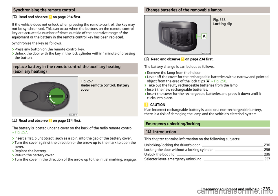
Fig. 257
Radio remote control: Battery
cover
Read and observe on page 234 first.
The battery is located under a cover on the back of the radio remote control
» Fig. 257 .
›
Insert a flat, blunt object, such as a coin, into the gap of the battery cover.
›
Turn the cover against the direction of the arrow up to the mark to open the
cover.
›
Replace the battery.
›
Return the battery cover.
›
Turn the cover in the direction of the arrow up to the initial marking, engage.
Change batteries of the removable lampsFig. 258
Locking clip
Read and observe on page 234 first.
The battery change is carried out as follows.
›
Remove the lamp from the holder.
›
Lever off the cover for the rechargeable batteries with a narrow and pointed
object from the area of the lock clips
A
» Fig. 258 .
›
Take out the faulty rechargeable batteries from the lamp.
›
Insert the new rechargeable batteries.
›
Insert the cover for the rechargeable batteries and press it down until it
clicks into place.
CAUTION
If an incorrect rechargeable battery is used or a non-rechargeable battery,
there is a risk of damaging the lamp and the vehicle's electrical system.
Emergency unlocking/locking
Introduction
This chapter contains information on the following subjects:
Unlocking/locking the driver's door
236
Locking the door without a locking cylinder
236
Unlock the boot lid
236
Selector lever-emergency unlocking
237235Emergency equipment and self-help
Page 238 of 276

Unlocking/locking the driver's doorFig. 259
Driver's door handle: masked lock cylinder / key rotations for un-
locking and locking
Fig. 260
Handle on the driver's door: Key / KESSY
The driver's door can be unlocked or locked in an emergency.
›
Pull on the door handle and hold in place.
›
Insert the vehicle key into the slot on the bottom of the cover » Fig. 259.
›
Open the cover in the direction of the arrow.
›
Release the door handle.
›
For vehicles with LHD insert the remote control key with the buttons facing
up into the lock cylinder and unlock or lock the vehicle.
›
For vehicles with RHD insert the remote control key directed with buttons
down into the lock cylinder and unlock or lock the vehicle.
On vehicles with the KESSY key point the emergency key with the handle
down into the key cylinder » Fig. 260.
›
Pull on the door handle and hold in place.
›Replace the cap in its original position.
CAUTION
Make sure you do not damage the paint when performing an emergency lock-
ing/unlocking.
Locking the door without a locking cylinder
Fig. 261
Emergency locking: Left/right rear door
An emergency locking mechanism, which is only visible after opening the door,
is located on the face side of the doors which have no locking cylinder.
›
Remove the cover
A
» Fig. 261 .
›
Insert the vehicle key into the slot and turn in the direction of the arrow
(sprung position).
›
Replace the cover
A
.
Unlock the boot lid
Fig. 262
Unlock boot lid: variant 1 / variant 2
The boot lid can be unlocked manually.
236Do-it-yourself
Page 242 of 276
Installing the storage compartment›Raise the storage compartment in the direction of the arrow 4.›
Overcome the resistance of the detents
A
.
›
Insert the brake control linkage in the opposite direction to arrow
2
.
›
Lock the brake control linkage in the opposite direction to arrow
1
.
›
Close the storage compartment.
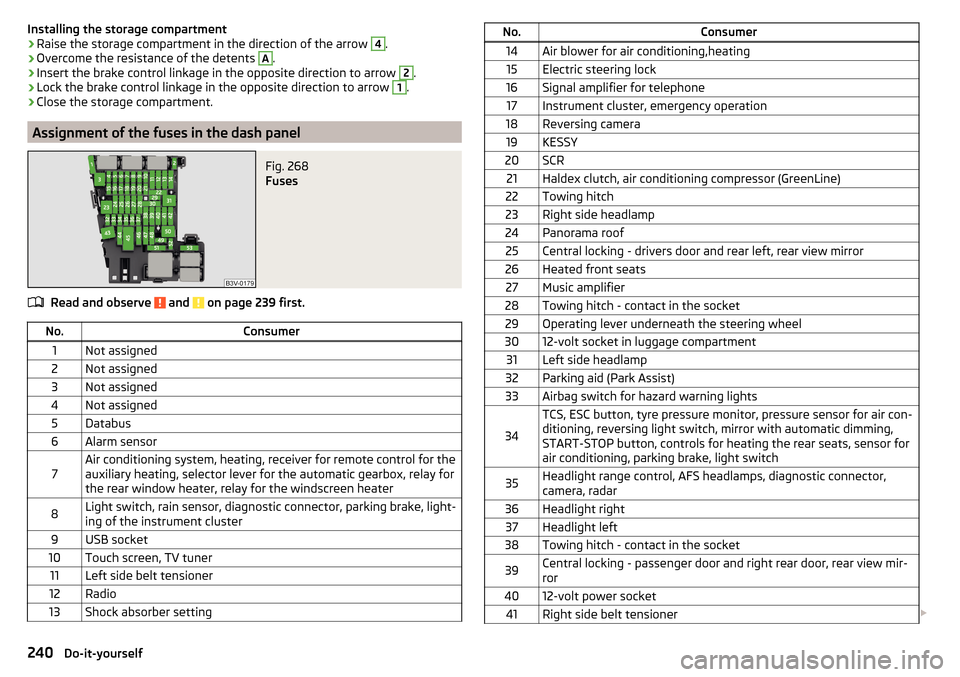
Assignment of the fuses in the dash panel
Fig. 268
Fuses
Read and observe and on page 239 first.
No.Consumer1Not assigned2Not assigned3Not assigned4Not assigned5Databus6Alarm sensor7Air conditioning system, heating, receiver for remote control for the
auxiliary heating, selector lever for the automatic gearbox, relay for
the rear window heater, relay for the windscreen heater8Light switch, rain sensor, diagnostic connector, parking brake, light-
ing of the instrument cluster9USB socket10Touch screen, TV tuner11Left side belt tensioner12Radio13Shock absorber settingNo.Consumer14Air blower for air conditioning,heating15Electric steering lock16Signal amplifier for telephone17Instrument cluster, emergency operation18Reversing camera19KESSY20SCR21Haldex clutch, air conditioning compressor (GreenLine)22Towing hitch23Right side headlamp24Panorama roof25Central locking - drivers door and rear left, rear view mirror26Heated front seats27Music amplifier28Towing hitch - contact in the socket29Operating lever underneath the steering wheel3012-volt socket in luggage compartment31Left side headlamp32Parking aid (Park Assist)33Airbag switch for hazard warning lights
34
TCS, ESC button, tyre pressure monitor, pressure sensor for air con-
ditioning, reversing light switch, mirror with automatic dimming,
START-STOP button, controls for heating the rear seats, sensor for
air conditioning, parking brake, light switch35Headlight range control, AFS headlamps, diagnostic connector,
camera, radar36Headlight right37Headlight left38Towing hitch - contact in the socket39Central locking - passenger door and right rear door, rear view mir-
ror4012-volt power socket41Right side belt tensioner 240Do-it-yourself
Page 259 of 276
automatic transmissionselector lever lock defect137
Automatic transmission135
Kick down138
Launch control138
Malfunctions37
Selector lever lock137
Warning light37
Warning messages37
AUX99
Auxiliary heating (auxiliary heating and ventila- tion)
123
Adjust124
Switching on/off124
Auxiliary heating (heating and ventilation) Radio remote control
125
Avoiding damage to your vehicle141
B
Bags on the backs of the front seats
97
on the inner sides of the front seats97
Battery In the remote control key
234
Replace the KESSY key234
Belts11
Belt tensioners14
Bonnet Closing
207
Opening207
Boot Class N1 vehicles
114
Non-contact opening61
See Boot lid59
Boot lid automatic locking
59
Closing59
Non-contact opening61
Opening59
Brake Information messages33
Warning light33
Brake Assist (HBA)145
Brake booster133
brake fluid specification
213
Brake fluid212
Checking212
Information messages33
Brake linings Warning light
36
Brake pedal (automatic transmission) Warning light
37
Brakes Brake booster
133
Brake fluid212
Braking and stabilisation systems143
Running-in139
Brakes and parking132
Brake system143
Braking Information on braking
132
Bulbs Replacing
242
C
Camera Lens care
197
Camera lens care
197
Car care Jack
197
Car computer see multifunction display
42
Care and maintenance190
Cargo element112
Car park134
Car park ticket holder91
Carrier Roof rack117
Cavity protection197
Central locking52
Problems57
Central locking button55
Change Bulb for indicator (halogen headlight)
243
engine oil209
light bulb in tail light244
Change engine oil
209
Changing Wheels
224
Changing a wheel Follow-up tasks
227
Preparation224
Changing wheels Wheel removal and fix
227
Charging a vehicle battery215
Checking Battery electrolyte level
214
Brake fluid212
Coolant211
Engine oil210
Oil level210
Windscreen washer fluid208
Checks Statutory checks
190
Children and safety20
Child safety Side airbag
22
Child safety lock57
Child safety seat Use of child safety seats
23
Child seat Classification
22
i-Size25
ISOFIX23
on the front passenger seat21
257Index
Page 261 of 276
Fuel supply30
Gear changes42
Service interval49
Disposal Acceptance and recycling of used vehicles
193
Distance driven31
Distance warning Warning light
40
Door Child safety lock
57
Closing56
Emergency locking236
Emergency locking the driver's door236
Opening56
Door warning41
Drive Driving through water
141
DriveGreen140
Driver Steering Recommendation (DSR)145
Driving Emissions
248
Fuel consumption248
through water141
driving data operation
43
Driving mode171
driving mode select Normal mode
172
Driving Mode Selection171
DSR145
Dynamic Light Assist72
E
ECO-TIP
49
Eco-tips49
Economical driving Tips
139
Economy mode Warning light
41
EDL145
Electrical boot lid set the top position of the lid
60
Electrical power windows Buttons in the driver's door
62
Electric boot lid Force limit
59
Manual operation59
Electric luggage compartment lid Malfunctions
61
Operating60
Electric parking brake133
Electric window lifter61, 63
Button in the passenger door63
Button in the rear doors63
Window operation malfunctions64
Electronic differential lock (EDL, XDS)145
Electronic immobilizer126
emergency replace battery in the remote control
235
Emergency Changing a wheel
224
Hazard warning light system71
Jump-starting230
Locking the door without a locking cylinder236
Locking the driver's door236
Selector lever-unlocking237
Switch off the engine by pressing a button129
Towing the using the tow hitch233
Towing the vehicle231
Tyre repair228
Unlocking the driver's door236
emergency equipment reflective vest
223
Emergency equipment Fire extinguisher
223
First aid kit222
Jack223
Vehicle tool kit223
Warning triangle222
Emissions248
Engine Information messages
38
Running-in139
Engine compartment206
Brake fluid212
Overview208
Vehicle battery213
Engine number246
engine oil specification
209
Engine oil209
Checking210
Replenishing210
Warning light38
EPC Warning light
35
ESC Operation
144
Warning light34
ESC Sport144
Exhaust emissions control system Warning light
34
F
Fastening elements
106
Fatigue detection182
Function182
Information messages182
Films195
Fire extinguisher223
First aid kit222
Floor covering Fixing
108
in the luggage compartment108
Fog lights Warning light
36
Fog Lights70
Fold in passenger's mirror80
259Index