air condition SKODA SUPERB 2015 3.G / (B8/3V) Owner's Guide
[x] Cancel search | Manufacturer: SKODA, Model Year: 2015, Model line: SUPERB, Model: SKODA SUPERB 2015 3.G / (B8/3V)Pages: 276, PDF Size: 42.14 MB
Page 171 of 276
The Front Assist (hereinafter referred to as the system) warns you of the dan-
ger of a collision with a vehicle or another obstacle in front of the vehicle, and
tries to avoid a collision or mitigate its consequences by automatically applying
the brakes where necessary.
The area in front of the vehicle is monitored by a radar sensor » page 143.WARNING■
Please take note of the general points relating to the use of assistance
systems » page 142, in section Introduction .■
The system does not respond to crossing or oncoming objects.
CAUTION
In case of failure of more than one brake light on the vehicle or on the electri-
cally connected trailer, the system becomes unavailable.
Operation
Read and observe
and on page 169 first.
The system support is provided in the following manner.▶ Alerts you about a dangerous proximity to the vehicle ahead.
▶ Warns you of an impending collision.
▶ Prepares the brakes for emergency braking prior to a detected danger.
▶ Assists with a brake action triggered by the driver.
▶ If the driver fails to respond to a detected danger, an automatic braking ac-
tion is performed.
The system can work only if the following basic conditions are met. The system is activated.
The TCS is activated » page 143, Braking and stabilisation systems .
The vehicle is moving forwards at a speed of more than approx. 5 km/h.
Note
The system can be impaired or may not be available, for example when driving
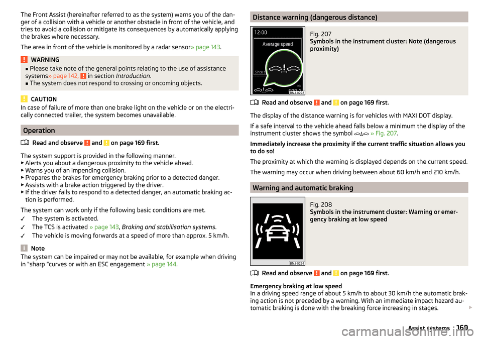
in “sharp ”curves or with an ESC engagement » page 144.Distance warning (dangerous distance)Fig. 207
Symbols in the instrument cluster: Note (dangerous
proximity)
Read and observe and on page 169 first.
The display of the distance warning is for vehicles with MAXI DOT display.
If a safe interval to the vehicle ahead falls below a minimum the display of the
instrument cluster shows the symbol
» Fig. 207 .
Immediately increase the proximity if the current traffic situation allows you
to do so!
The proximity at which the warning is displayed depends on the current speed.
The warning may occur when driving between about 60 km/h and 210 km/h.
Warning and automatic braking
Fig. 208
Symbols in the instrument cluster: Warning or emer-
gency braking at low speed
Read and observe and on page 169 first.
Emergency braking at low speed
In a driving speed range of about 5 km/h to about 30 km/h the automatic brak- ing action is not preceded by a warning. With an immediate impact hazard au-
tomatic braking is done with the breaking force increasing in stages.
169Assist systems
Page 174 of 276

Normal
Read and observe on page 171 first.
This mode is suitable for a conventional driving.
Sport
mode
Read and observe
on page 171 first.
This mode is suitable for a sporty driving.
Selecting this mode primarily affects the function of the following systems.
DCC
The DCC adjusts the chassis for the sporty driving style.
Steering
The power steering is reduced slightly, i.e., the driver needs to exert more
force for steering .
Engine / drive
The vehicle acceleration is more dynamic than in
Normal
mode.
Adaptive Cruise Control (ACC)
The acceleration is quicker than in
Normal
mode with distance control
» page 163 .
Xenon headlight
The headlamps adapt to the driving style more dynamically than in mode
Nor-mal
» page 69 .
ProActive passenger protection
The first level of protection is deactivated » page 173.
Eco
mode
Read and observe
on page 171 first.
This mode is suitable for a relaxed style of driving and helps to save fuel.
Selecting this mode primarily affects the function of the following systems.
Engine / drive
Vehicle acceleration is more relaxed than in
Normal
mode.
The recommended gear is controlled such to achieve the lowest possible fuel
consumption » page 42.
When the START-STOP system was deactivated manually » page 130, it is au-
tomatically activated.
The automatic gearbox is set automatically to mode E » page 135 .
Adaptive Cruise Control (ACC)
Acceleration occurs more relaxed than in Normal
» page 163 mode with distance
control.
Xenon headlight
The system is in economic mode » page 69. The headlamps are in basic setting
and do not adapt to the direction of travel.
Air conditioning (Climatronic)
The air conditioning is controlled so as to save energy. For this reason, for ex-
ample, it may take longer to reach the desired interior temperature in mode
Normal
.
Note
■ The mode Eco is not available when towing a trailer or when another acces-
sory is connected to the trailer socket. If the vehicle is in drive mode Eco
and a
trailer is hitched up or another accessory is connected, the vehicle is automati-
cally set to the driving mode
Normal
.
■
The maximum vehicle acceleration (kick down function) is possible also in
driving mode
Eco
.
Individual
mode
Read and observe
on page 171 first.
In the mode
Individual
each system can be set independently » page 173, Mode
settings
Individual
.
172Driving
Page 175 of 276
Mode selection and Infotainment displayFig. 210
Button for selecting the driving mode / Display in Infotainment
display
Read and observe
on page 171 first.
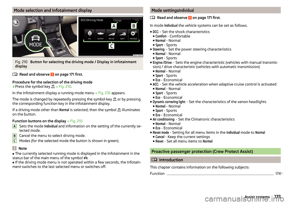
Procedure for the selection of the driving mode
›
Press the symbol key
» Fig. 210 .
In the Infotainment display a running mode menu » Fig. 210 appears.
The mode is changed by repeatedly pressing the symbol key or by pressing
the corresponding function key in the Infotainment display.
If a driving mode other than
Normal
is selected, then the symbol illuminates
on the button.
Function buttons on the display » Fig. 210
Sets the mode
Individual
and information on the setting of the currently se-
lected mode.
Cancel the menu to select driving mode.
Modes (for the selected mode the button is shown in green).
Note
■ The currently selected running mode is displayed in the Infotainment in the
status bar of the main menu of the symbol .■
If the driving mode menu is not operated within a few seconds, the Infotain-
ment switches to the last selected menu or switches off.
ABCMode settingsIndividual
Read and observe on page 171 first.
In mode
Individual
the vehicle systems can be set as follows.
■
DCC:
- Set the shock characteristics
■
Comfort
- Comfortable
■
Normal
- Normal
■
Sport
- Sports
■
Steering:
- Set the power steering characteristics
■
Normal
- Normal
■
Sport
- Sports
■
Engine:
/
Drive:
- Sets the engine characteristic (vehicles with manual transmis-
sion) / drive characteristic (vehicles with automatic transmission)
■
Normal
- Normal
■
Sport
- Sports
■
Eco
- Economical
■
ACC:
- Set the vehicle acceleration when adaptive cruise control is activated
■
Normal
- Normal
■
Sport
- Sports
■
Eco
- Economical
■
Dynamic cornering light:
- Set the characteristics of the xenon headlights
■
Normal
- Normal
■
Sport
- Sports
■
Eco
- Economical
■
Air conditioning:
- Set the Climatronic characteristics
■
Normal
- Normal
■
Eco
- Economical
■
Reset mode
- Setting for all menu items in the
Individual
mode to
Normal
■
Cancel
- Keep the current settings
■
Reset
- Set all menu items to
Normal
Proactive passenger protection (Crew Protect Assist)
Introduction
This chapter contains information on the following subjects:
Function
174
173Assist systems
Page 179 of 276
Assistant for “blind spot monitoring”
Introduction
This chapter contains information on the following subjects:
Operation
177
Driving conditions and warnings
178
Activation / deactivation
178
Information messages
179
The assistant for“blind spot monitoring” (following known as system) draws
attention to vehicles travelling in the same direction in the next lane in the so
called blind spots.
The “blind spot” is an area that is not easily visible in a rear-view mirror or even
directly from the vehicle.
WARNING■ Please take note of the general points relating to the use of assistance
systems » page 142, in section Introduction .WARNINGThe system has physical and system-related limitations. Therefore, in the
following situations the system can be delayed in drawing attention (or not
at all) to a vehicle in the next land. The responsibility for the lane change
rests with the driver.■
When a vehicle is approaching at a very high speed.
■
When passing through a very sharp curve or a roundabout.
Operation
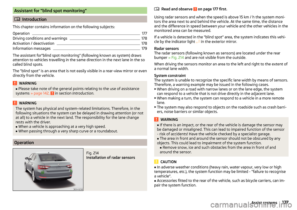
Fig. 214
Installation of radar sensors
Read and observe on page 177 first.
Using radar sensors and when the speed is above 15 km / h the system moni- tors the area next to and behind the vehicle. At the same time, the distance
and the difference in speed between your vehicle and the other vehicles in the
monitored area can be measured.
If a vehicle is detected in the “blind spot” area, the system indicates this vehi-
cle by the indicator light in the exterior mirror.
Radar sensors
The radar sensors (following known as sensors) are located under the rear
bumper » Fig. 214 and are not visible from the outside.
When driving the sensors monitor an area to the left and right to the extent of
a normal lane width.
System constraint
The system is unable to recognize the specific lane width by means of sensors. Therefore, a warning example may be issued in the following cases.
▶ When driving on a road with narrow lanes or on the lane edge, the system
can respond to a vehicle that is not drive directly in the adjacent lane.
▶ When making a turn, the system can respond to a vehicle in a more remote
lane.
▶ The system may also respond to objects on the roadside such as crash barri-
ers, noise barriers or similar objects.
WARNING■ If there is an impact, or the rear of the vehicle is damage the sensor may
be damaged or misaligned. This can lead to impaired function of the sensor
- risk of accidents! Have the vehicle checked by a specialist garage.■
The area in front and around the sensor should not be obscured by any
objects. This could lead to impairment of the system function. ■ Remove snow, ice and such obstacles from the area in front of and
around the sensor.
CAUTION
■ In adverse weather conditions (heavy rain, water vapour, very low or high
temperatures, etc.), the system function may be limited - “failure to recognise
a vehicle”.■
Accessories fitted to the rear of the vehicle, such as bicycle carriers, can im-
pair the system function.
177Assist systems
Page 192 of 276

General Maintenance
Care and maintenance
Service work, adjustments and technical alterations
Introduction
This chapter contains information on the following subjects:
Vehicle operating under different weather conditions
190
Statutory checks
190
ŠKODA Service Partners
191
ŠKODA Original parts
191
ŠKODA Original accessories
191
Spoiler
192
Component protection
192
Airbags
192
Acceptance and recycling of used vehicles
193
The instructions and guidelines from ŠKODA AUTO a.s. must be observed when
carrying out any modifications, repairs or technical alterations to your vehicle.
Adhering to these instructions and guidelines helps ensure road safety and
helps keep your vehicle in a good technical condition. After carrying out modifi-
cations, repairs or technical alterations, the vehicle will comply with German
road transport regulations (StVZO).
Always consult a ŠKODA Partner » page 191 before buying accessories or
parts, or before carrying out any modifications, repairs or technical alterations
to your vehicle.
WARNING■ Work on your vehicle, which have been carried out unprofessionally, can
cause operational faults – risk of accident!■
Interference on the electronic components and their software can lead to
operational faults. This interference can also impair not directly affected
systems because of the networking of the electronic components. The op-
erational safety of the vehicle may be at significant risk and can lead to in-
creased wear of parts.
For the sake of the environmentTechnical documents regarding alterations carried out on the vehicle must be
kept by the vehicle user in order to be handed over to the recyclers at a later
date. This ensures that the vehicle is recycled in an environmentally sound
manner.
Note
■ We recommend only having these modifications, repairs and technical
changes performed by a specialist garage.■
Any damage caused by technical alterations made without the approval of
the manufacturer is excluded from the warranty » Service schedule .
■
The ŠKODA Partner accepts no liability for products that have not been ap-
proved by ŠKODA AUTO a.s. even though these may be products with an op-
erational approval or that have been approved by a government testing insti-
tute.
■
We advise you only to use ŠKODA Original Accessories and ŠKODA Original
Parts which have been expressly approved for use on your vehicle. Reliability,
safety and suitability for your vehicle are guaranteed with these.
■
ŠKODA Original Accessories and ŠKODA Original Parts can be purchased from
ŠKODA Partners, who will also perform the professional assembly of the pur-
chased parts.
Vehicle operating under different weather conditions
Read and observe
on page 190 first.
If you would like to operate your vehicle in countries other than those with itsintended weather conditions, you should contact a ŠKODA Partner.
She will advise you if certain precautions need to be taken to ensure the full
functioning of the vehicle and to prevent damage.
This involves, for example, the coolant, battery replacement and the like.
Statutory checks
Read and observe
on page 190 first.
Many countries have legislation requiring the operational reliability and roadworthiness and/or exhaust gas properties of a vehicle to be tested at specific
intervals. These tests can be carried out by workshops or testing stations that
have been legally authorized for this purpose.
190General Maintenance
Page 193 of 276

The ŠKODA Service Partners are up-to-date on the legally required tests and
will prepare the vehicle for the tests as part of a service operation if required,
or will be responsible for carrying out these tests. The specialist garages can
carry out the specified tests directly if required by the customer if they are au-
thorised to do so. This saves you time and money.
Even if you want to take your vehicle to an officially approved test centre for
prior checking in preparation of a legally required test, we recommend that you
consult the service consultant of your ŠKODA Service Partner beforehand.
Based on their appraisal, the service consultant will tell you which areas you
should focus on in order to ensure that your vehicle will pass the technical test
without any problems. This allows you to avoid additional expenses resulting
from a possible subsequent test.
ŠKODA Service Partners
Read and observe
on page 190 first.
ŠKODA Service Partners feature modern, specially developed tools and equip-
ment. Here, trained specialists have access to a comprehensive range of
ŠKODA Original Parts and ŠKODA Original Accessories for carrying out modifi-
cations, repairs and technical alterations.
All ŠKODA service partners operate according to the most recent guidelines
and instructions from ŠKODA AUTO a.s. All service and repair work is therefore
carried out on time and at the appropriate quality. Adhering to these instruc-
tions and guidelines helps ensure road safety and helps keep your vehicle in a
good technical condition.
ŠKODA Service Partners are therefore properly prepared to service your vehicle
and to provide quality work. We therefore advise you to have all modifications,
repairs and technical alterations to your vehicle carried out by a ŠKODA Service
Partner.
ŠKODA Original parts
Read and observe
on page 190 first.
We recommend the use of ŠKODA Genuine Parts for your vehicle, as these
parts are approved by ŠKODA AUTO a.s.. They correspond precisely to the
ŠKODA AUTO a.s. regulations with regard to design, dimensional accuracy and
material, and are identical to the components used in series production.
ŠKODA AUTO a.s. is able to vouch for the safety, suitability and long service life of these products. We therefore recommend that you only use ŠKODA Genuine
Parts.
ŠKODA AUTO a.s. supplies the market with a complete range of ŠKODA Genu-
ine Parts - not only while the model is still in production but for at least 15
years after the end of series production for wear parts and at least 10 years
after the end of series production for all other vehicle parts.
ŠKODA Service Partners are liable for any defects of ŠKODA Genuine Parts for a period of 2 years after sale in accordance with the materials defect liability,
unless agreed otherwise in the purchase agreement. You should keep the ap-
proved warranty certificate and the invoices for these components for this pe-
riod of time, so that the commencement of the term can be verified.
Body repairs
ŠKODA vehicles are designed such that if any damage occurs to the body, it is
only necessary to replace those parts that are actually damaged.
However, before you decide to have damaged body parts replaced, you should
first of all contact your specialist garage to determine whether or not the parts
can also be repaired. Repairs to body parts are usually cheaper.
ŠKODA Original accessories
Read and observe
on page 190 first.
If you wish to fit accessories to your vehicle, you should remember the follow-ing.
We recommend that you use ŠKODA Genuine Accessories in your vehicle.
ŠKODA AUTO a.s. has selected these accessories to ensure that they are relia-
ble, safe and suitable for your particular vehicle. Although we constantly moni-
tor the market, we are not able to assess or vouch for other products even
though in some instances such parts may have operational approval or may
have been approved by a nationally recognised testing laboratory.
All accessory products are subjected to a challenging process in the areas of technical development (technical testing) and quality inspection (customer
testing), and the product only becomes a ŠKODA Genuine Accessory if all tests
are passed.
Our ŠKODA Genuine Accessories service also includes expert advice and pro-
fessional fitting if required by the customer.
191Care and maintenance
Page 213 of 276

The proportion of coolant additive in the mixture must be at least 40%.
The coolant additive may be increased to a maximum of 60%.
The correct mixing ratio of water and coolant additive is to be checked if nec-
essary by a specialist garage or is to be restored if necessary.
The description of the coolant is shown in the coolant expansion reservoir
» Fig. 231 on page 211 .WARNINGThe engine compartment of your car is a hazardous area. The following
warning instructions must be followed at all times when working in the en- gine compartment » page 206.■
The coolant is harmful to health.
■
Avoid contact with the coolant.
■
Coolant vapours are harmful to health.
■
Never open the end cover of the coolant expansion reservoir while the
engine is still warm. The cooling system is pressurized!
■
When opening the end cover of the coolant expansion reservoir, cover it
with a cloth to protect your face, hands and arms from hot steam or hot
coolant.
■
If any coolant splashes into your eyes, immediately rinse out your eyes
with clear water and contact a doctor as soon as possible.
■
Always keep the coolant in the original container, safe from people who
are not completely independent, especially children - there is a danger of
poisoning!
■
If coolant is swallowed, consult a doctor immediately.
■
Never spill operating fluids over the hot engine - risk of fire.
CAUTION
■ Do not continue if for some reason it is not possible to fill with coolant un-
der the current circumstances! Switch off the engine and seek assistance from
a specialist garage.■
If the expansion tank is empty, do not top up with coolant. The system could
ventilate - there is a risk of engine damage,
not continue! Switch off the en-
gine and seek assistance from a specialist garage.
■
The concentration of coolant additive in the coolant must never be under
40%.
■
Over 60% of coolant additive in the coolant reduces the antifreeze protec-
tion and cooling effect.
■
A coolant additive that does not comply with the correct specification can
significantly reduce the corrosion protection of the cooling system.
■ Any faults resulting from corrosion may cause a loss of coolant and can con-
sequently result in major engine damage.■
Do not fill the coolant above the mark
A
» Fig. 231 on page 211 .
■
If an error occurs, leading to the engine overheating, the help of a professio-
nal garage is to be sought - there is a risk of serious engine damage occurring.
■
Additional headlights and other attached components in front of the air inlet
impair the cooling efficiency of the coolant.
■
Never cover the radiator - there is a risk of the engine overheating.
Note
The coolant capacity is approximately 1 l greater on vehicles that are fitted
with an auxiliary heater (auxiliary heating and ventilation).
Checking the coolant level
Fig. 231
Coolant expansion reservoir
Read and observe and on page 211 first.
The coolant expansion bottle is located in the engine compartment.
Coolant expansion reservoir » Fig. 231
Mark for the maximum permissible coolant level
Mark for the lowest permissible coolant level
The coolant level should be kept between the marks
A
and
B
.
The coolant can be checked and topped up, if the following conditions are sat-
isfied.
The vehicle is standing on a horizontal surface.
The engine is turned off.
The engine is not heated.
The bonnet is open.
AB211Inspecting and replenishing
Page 214 of 276
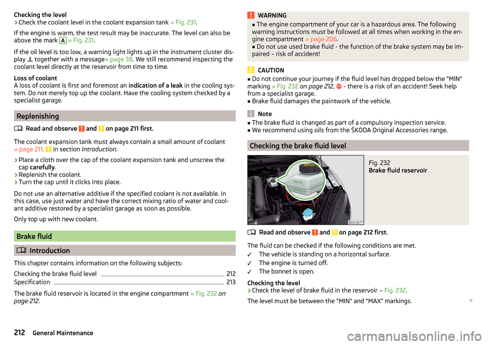
Checking the level›Check the coolant level in the coolant expansion tank » Fig. 231.
If the engine is warm, the test result may be inaccurate. The level can also be
above the mark A
» Fig. 231 .
If the oil level is too low, a warning light lights up in the instrument cluster dis-
play
together with a message » page 38. We still recommend inspecting the
coolant level directly at the reservoir from time to time.
Loss of coolant
A loss of coolant is first and foremost an indication of a leak in the cooling sys-
tem. Do not merely top up the coolant. Have the cooling system checked by a
specialist garage.
Replenishing
Read and observe
and on page 211 first.
The coolant expansion tank must always contain a small amount of coolant» page 211, in section Introduction .
›
Place a cloth over the cap of the coolant expansion tank and unscrew the
cap carefully .
›
Replenish the coolant.
›
Turn the cap until it clicks into place.
Do not use an alternative additive if the specified coolant is not available. In
this case, use just water and have the correct mixing ratio of water and cool-
ant additive restored by a specialist garage as soon as possible.
Only top up with new coolant.
Brake fluid
Introduction
This chapter contains information on the following subjects:
Checking the brake fluid level
212
Specification
213
The brake fluid reservoir is located in the engine compartment » Fig. 232 on
page 212 .
WARNING■
The engine compartment of your car is a hazardous area. The following
warning instructions must be followed at all times when working in the en-
gine compartment » page 206.■
Do not use used brake fluid - the function of the brake system may be im-
paired – risk of accident!
CAUTION
■ Do not continue your journey if the fluid level has dropped below the “MIN”
marking » Fig. 232 on page 212 , - there is a risk of an accident! Seek help
from a specialist garage.■
Brake fluid damages the paintwork of the vehicle.
Note
■ The brake fluid is changed as part of a compulsory inspection service.■We recommend using oils from the ŠKODA Original Accessories range.
Checking the brake fluid level
Fig. 232
Brake fluid reservoir
Read and observe and on page 212 first.
The fluid can be checked if the following conditions are met.
The vehicle is standing on a horizontal surface.
The engine is turned off.
The bonnet is open.
Checking the level
›
Check the level of brake fluid in the reservoir » Fig. 232.
The level must be between the “MIN” and “MAX” markings.
212General Maintenance
Page 242 of 276
Installing the storage compartment›Raise the storage compartment in the direction of the arrow 4.›
Overcome the resistance of the detents
A
.
›
Insert the brake control linkage in the opposite direction to arrow
2
.
›
Lock the brake control linkage in the opposite direction to arrow
1
.
›
Close the storage compartment.
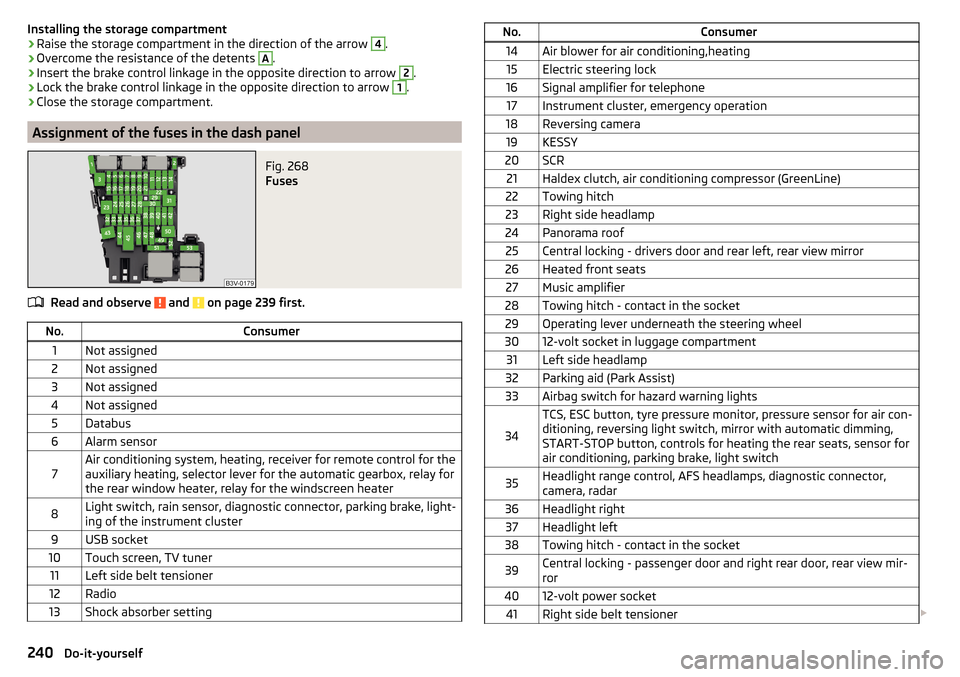
Assignment of the fuses in the dash panel
Fig. 268
Fuses
Read and observe and on page 239 first.
No.Consumer1Not assigned2Not assigned3Not assigned4Not assigned5Databus6Alarm sensor7Air conditioning system, heating, receiver for remote control for the
auxiliary heating, selector lever for the automatic gearbox, relay for
the rear window heater, relay for the windscreen heater8Light switch, rain sensor, diagnostic connector, parking brake, light-
ing of the instrument cluster9USB socket10Touch screen, TV tuner11Left side belt tensioner12Radio13Shock absorber settingNo.Consumer14Air blower for air conditioning,heating15Electric steering lock16Signal amplifier for telephone17Instrument cluster, emergency operation18Reversing camera19KESSY20SCR21Haldex clutch, air conditioning compressor (GreenLine)22Towing hitch23Right side headlamp24Panorama roof25Central locking - drivers door and rear left, rear view mirror26Heated front seats27Music amplifier28Towing hitch - contact in the socket29Operating lever underneath the steering wheel3012-volt socket in luggage compartment31Left side headlamp32Parking aid (Park Assist)33Airbag switch for hazard warning lights
34
TCS, ESC button, tyre pressure monitor, pressure sensor for air con-
ditioning, reversing light switch, mirror with automatic dimming,
START-STOP button, controls for heating the rear seats, sensor for
air conditioning, parking brake, light switch35Headlight range control, AFS headlamps, diagnostic connector,
camera, radar36Headlight right37Headlight left38Towing hitch - contact in the socket39Central locking - passenger door and right rear door, rear view mir-
ror4012-volt power socket41Right side belt tensioner 240Do-it-yourself
Page 248 of 276

Technical data
Technical data
Basic vehicle data
Introduction
This chapter contains information on the following subjects:
Vehicle characteristics
246
Operating weight
247
Payload
248
Measurement of fuel consumption and CO 2 emissions according to ECE
Regulations and EU Directives
248
Dimensions - Superb
249
Dimensions - Superb estate
250
Overhang angle
251
The details given in the vehicle's technical documentation always take prece-
dence over the details in the Owner's Manual.
The listed performance values were determined without performance-reduc- ing equipment, e.g. air conditioning system.
The values given have been determined in accordance with the rules and con-
ditions specified in statutory or technical regulations for determining opera-
tional and technical data for motor vehicles.
The values listed are for the basic model without any optional equipment.
Vehicle characteristicsFig. 277
Vehicle data sticker/type plate
Vehicle data sticker
The vehicle data sticker » Fig. 277 -
is located on the base of the luggage
compartment and is also fixed into the service schedule.
The vehicle data sticker contains the following data. Vehicle identification number (VIN)
Vehicle type
Gearbox code/paint number/interior equipment/engine output/engine code
Partial vehicle description
Approved tyre diameter in inches 1)
The approved tyres and rim sizes for your vehicle are listed in the vehicle's
technical documentation (the so called COC document) and this also states the
declaration of conformity.
Type plate
The type plate » Fig. 277 -
is located at the bottom of the B-pillar on the
right driver's side.
The type plate contains the following data. Manufacturer
Vehicle identification number (VIN)
Maximum permissible gross weight
Maximum permissible towed weight (towing vehicle and trailer)
1234567891)
Only valid for some countries.
246Technical data