engine coolant SKODA SUPERB 2015 3.G / (B8/3V) Owner's Manual
[x] Cancel search | Manufacturer: SKODA, Model Year: 2015, Model line: SUPERB, Model: SKODA SUPERB 2015 3.G / (B8/3V)Pages: 276, PDF Size: 42.14 MB
Page 5 of 276
Traffic jam assistant179Assistant for emergencies179
Traffic sign recognition
180
Fatigue detection
182
Tyre pressure monitoring
183
Hitch and trailer
184
Hitch
184
Trailer
185
General Maintenance
Care and maintenance
190
Service work, adjustments and technical
alterations
190
Washing vehicle
193
Cleaning vehicle exterior
194
Interior care
198
Inspecting and replenishing
201
Fuel
201
AdBlue ®
and its refilling
204
Engine compartment
206
Engine oil
209
Coolant
210
Brake fluid
212
Vehicle battery
213
Wheels
217
Tyres and wheel rims
217
Winter operation
220
Do-it-yourself
Emergency equipment and self-help
222
Emergency equipment
222
Changing a wheel
224
Puncture repair kit
228
Jump-starting
230
Towing the vehicle
231
Remote control and removable light
233Emergency unlocking/locking235Replacing windscreen wiper blades237
Fuses and light bulbs
238
Fuses
238
Bulbs
242
Technical data
Technical data
246
Basic vehicle data
246
Vehicle-specific information depending on
engine type
252
Index
3Table of Contents
Page 10 of 276
Safety
Passive Safety
General information
Introduction
This chapter contains information on the following subjects:
Before setting off
8
Driving safety
8
In this section of the instructions you will find important information, tips and
notes on the subject of passive safety.
We have combined everything here which you should be familiar with, for ex-
ample, regarding seat belts, airbags, safety of children and anything similar.
You can find further information on safety concerning you and those travelling
with you in the following chapters of this Owner's Manual.
The complete on-board literature should therefore always be in the vehicle.
This applies in particular, if you rent out or sell the vehicle.
Before setting off
For your own safety and the safety of the people travelling with you, please
pay attention to the following points before setting off.
▶ Ensure that the lighting and the turn signal system are functioning properly.
▶ Ensure that the function of the wipers and the condition of the wiper blades
are free of any defects.
▶ Ensure that all of the windows offer good visibility to the outside.
▶ Adjust the rear-view mirror so that vision to the rear is guaranteed.
▶ Ensure that the mirrors are not covered.
▶ Check the tyre inflation pressure.
▶ Check the engine oil, brake fluid and coolant level.
▶ Secure all items of luggage.
▶ Do not exceed the permissible axle loads and permissible gross weight of the
vehicle.
▶ Close all doors as well as the bonnet and boot lid.
▶ Ensure that no objects can obstruct the pedals.
▶
Protect children in suitable child seats with correctly fastened seat belts
» page 20 , Transporting children safely .
▶ Adopt the correct seated position » page 8, Correct and safe seated posi-
tion . Tell your passengers to assume the correct seated position.
Driving safety
The driver is fully responsible for himself and passengers, especially children. If
your driving safety is effected, you place yourself and the oncoming traffic at
risk.
The following guidelines must therefore be observed. ▶ Do not become distracted from concentrating on the traffic situation, (e.g. by
your passengers or mobile phone calls).
▶ Never drive when your driving ability is impaired, (e.g. due to medication, al-
cohol or drugs).
▶ Keep to the traffic regulations and the permissible speed limit.
▶ Always adjust the driving speed to the road, traffic and weather conditions.
▶ Take regular breaks on long journeys (at least every two hours).
The following list contains instructions for the Passenger which, if not ob-
served, may cause serious injuries or death. ▶ Do not lean against the dash panel.
▶ Do not put your feet on the dash panel.
The following list contains instructions for all Passengers which, if not ob-
served, may cause serious injuries or death. ▶ Do not sit only on the front part of the seat.
▶ Do not sit facing to the side.
▶ Do not lean out of the window.
▶ Do not put your limbs out of the window.
▶ Do not put your feet on the seat cushion.
Correct and safe seated position
Introduction
This chapter contains information on the following subjects:
Correct seat position of the driver
9
Adjusting the steering wheel position
9
Correct seated position for the front passenger
10
Correct seated position for the passengers in the rear seats
10
8Safety
Page 30 of 276

Storage compartment with bottle storage91
Waste container
93
Note
The arrangement of the controls right-hand drive models may differ from the
layout shown in » Fig. 21. The symbols on the controls and switches are the
same as for left-hand drive models.3839Instruments and warning lights
Instrument cluster
Introduction
This chapter contains information on the following subjects:
Overview
29
Revolutions counter
29
Display
29
Coolant temperature gauge
30
Fuel gauge
30
Counter for distance driven
31
Setting the clock
31
Display in rear centre console
31
The instrument cluster gives the driver basic information such as the current
speed, engine speed, the state of some vehicle systems and the like.
If there is a fault in the instrument cluster, the following message will appear
in the display.
Error: instrument cluster. Workshop!COMBI-INSTRUM_ WORKSHOP
Seek help from a specialist garage.
WARNINGConcentrate fully at all times on your driving! As the driver, you are fully re-
sponsible for road safety.
Note
■ If the message SAFE CP appears in the instrument cluster display, the compo-
nent protection for the instrument cluster is active. Further information
» page 192 , Component protection .■
With the ignition switched on the instruments are also illuminated. The
brightness of the instrument illumination is set automatically depending on
the ambient lighting throughout.
28Using the system
Page 31 of 276
OverviewFig. 22
Instrument cluster
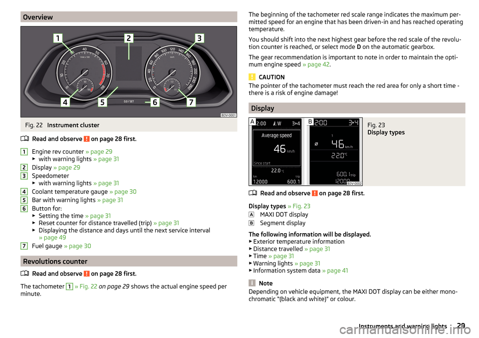
Read and observe
on page 28 first.
Engine rev counter » page 29
▶ with warning lights » page 31
Display » page 29
Speedometer
▶ with warning lights » page 31
Coolant temperature gauge » page 30
Bar with warning lights » page 31
Button for: ▶ Setting the time » page 31
▶ Reset counter for distance travelled (trip) » page 31
▶ Displaying the distance and days until the next service interval
» page 49
Fuel gauge » page 30
Revolutions counter
Read and observe
on page 28 first.
The tachometer
1
» Fig. 22 on page 29 shows the actual engine speed per
minute.
1234567The beginning of the tachometer red scale range indicates the maximum per-
mitted speed for an engine that has been driven-in and has reached operating
temperature.
You should shift into the next highest gear before the red scale of the revolu-
tion counter is reached, or select mode D on the automatic gearbox.
The gear recommendation is important to note in order to maintain the opti-
mum engine speed » page 42.
CAUTION
The pointer of the tachometer must reach the red area for only a short time -
there is a risk of engine damage!
Display
Fig. 23
Display types
Read and observe on page 28 first.
Display types » Fig. 23
MAXI DOT display
Segment display
The following information will be displayed.
▶ Exterior temperature information
▶ Distance travelled » page 31
▶ Time » page 31
▶ Warning lights » page 31
▶ Information system data » page 41
Note
Depending on vehicle equipment, the MAXI DOT display can be either mono-
chromatic “(black and white)” or colour.29Instruments and warning lights
Page 32 of 276
Coolant temperature gaugeFig. 24
Coolant temperature gauge
Read and observe on page 28 first.
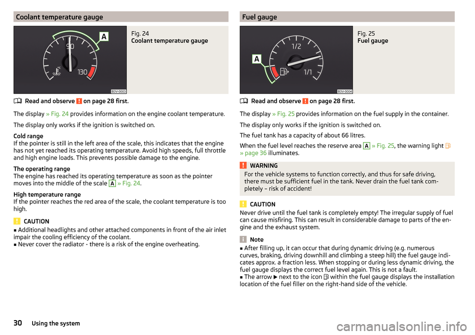
The display » Fig. 24 provides information on the engine coolant temperature.
The display only works if the ignition is switched on.
Cold range
If the pointer is still in the left area of the scale, this indicates that the engine has not yet reached its operating temperature. Avoid high speeds, full throttle
and high engine loads. This prevents possible damage to the engine.
The operating range
The engine has reached its operating temperature as soon as the pointer
moves into the middle of the scale
A
» Fig. 24 .
High temperature range
If the pointer reaches the red area of the scale, the coolant temperature is too
high.
CAUTION
■ Additional headlights and other attached components in front of the air inlet
impair the cooling efficiency of the coolant.■
Never cover the radiator - there is a risk of the engine overheating.
Fuel gaugeFig. 25
Fuel gauge
Read and observe on page 28 first.
The display » Fig. 25 provides information on the fuel supply in the container.
The display only works if the ignition is switched on.
The fuel tank has a capacity of about 66 litres.
When the fuel level reaches the reserve area
A
» Fig. 25 , the warning light
» page 36 illuminates.
WARNINGFor the vehicle systems to function correctly, and thus for safe driving,
there must be sufficient fuel in the tank. Never drain the fuel tank com-
pletely – risk of accident!
CAUTION
Never drive until the fuel tank is completely empty! The irregular supply of fuel
can cause misfiring. This can result in considerable damage to parts of the en-
gine and the exhaust system.
Note
■ After filling up, it can occur that during dynamic driving (e.g. numerous
curves, braking, driving downhill and climbing a steep hill) the fuel gauge indi-
cates approx. a fraction less. When stopping or during less dynamic driving, the
fuel gauge displays the correct fuel level again. This is not a fault.■
The arrow
next to the icon
within the fuel gauge displays the installation
location of the fuel filler on the right-hand side of the vehicle.
30Using the system
Page 34 of 276
Engine electronics check (petrol engine)35 Safety systems35
Tyre pressure
35
Brake linings
36
Fuel reserve
36
Lane departure warning (Lane Assist)
36
Turn signal system
36
Trailer turn signal lights
36
Fog lights
36
Speed regulating system / Speed limiter
37
Brake pedal (automatic transmission)
37
Parking brake - Auto Hold function
37
Main beam
37
Automatic transmission
37
Rear seat belt warning light
37
Alternator
37
Coolant
38
Engine oil pressure too low
38
Engine oil level
38
AdBlue ®
39
Lamp failure
39
Diesel particulate filter (diesel engine)
39
Windscreen washer fluid level
40
Headlamp assistant
40
START-STOP system
40
Low temperature displayed
40
Water in the fuel filter (diesel engine)
40
Automatic Distance Control (ACC)
40
Distance warning (Front Assist)
40
Advance warning / emergency braking (Front Assist)
41
Economy mode
41
Adaptive chassis control (DCC) fault
41
Service
41
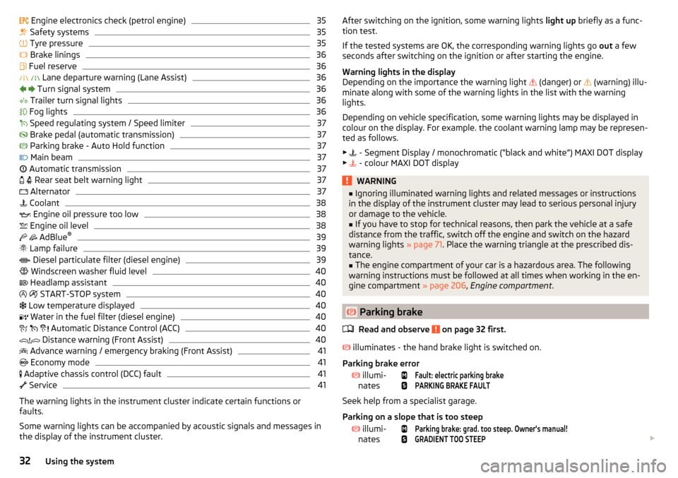
The warning lights in the instrument cluster indicate certain functions or
faults.
Some warning lights can be accompanied by acoustic signals and messages in
the display of the instrument cluster.
After switching on the ignition, some warning lights light up briefly as a func-
tion test.
If the tested systems are OK, the corresponding warning lights go out a few
seconds after switching on the ignition or after starting the engine.
Warning lights in the display
Depending on the importance the warning light
(danger) or
(warning) illu-
minate along with some of the warning lights in the list with the warning
lights.
Depending on vehicle specification, some warning lights may be displayed in
colour on the display. For example. the coolant warning lamp may be represen-
ted as follows.
▶ - Segment Display / monochromatic (“black and white”) MAXI DOT display
▶ - colour MAXI DOT displayWARNING■
Ignoring illuminated warning lights and related messages or instructions
in the display of the instrument cluster may lead to serious personal injury
or damage to the vehicle.■
If you have to stop for technical reasons, then park the vehicle at a safe
distance from the traffic, switch off the engine and switch on the hazard
warning lights » page 71. Place the warning triangle at the prescribed dis-
tance.
■
The engine compartment of your car is a hazardous area. The following
warning instructions must be followed at all times when working in the en-
gine compartment » page 206, Engine compartment .
Parking brake
Read and observe
on page 32 first.
illuminates - the hand brake light is switched on.
Parking brake error
illumi-
nates
Fault: electric parking brakePARKING BRAKE FAULT
Seek help from a specialist garage.
Parking on a slope that is too steep
illumi-
nates
Parking brake: grad. too steep. Owner's manual!GRADIENT TOO STEEP
32Using the system
Page 40 of 276
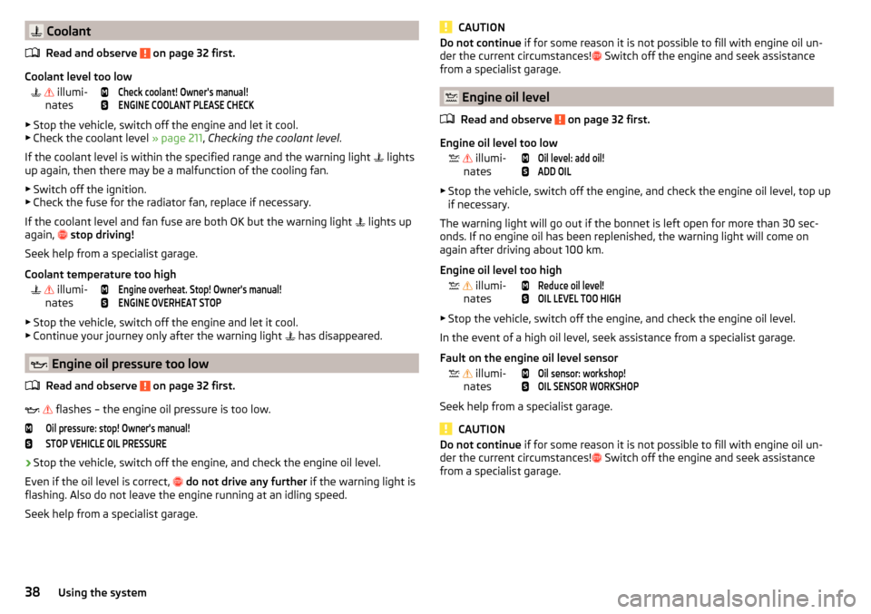
CoolantRead and observe
on page 32 first.
Coolant level too low
illumi-
nates
Check coolant! Owner's manual!ENGINE COOLANT PLEASE CHECK
▶ Stop the vehicle, switch off the engine and let it cool.
▶ Check the coolant level » page 211, Checking the coolant level .
If the coolant level is within the specified range and the warning light
lights
up again, then there may be a malfunction of the cooling fan.
▶ Switch off the ignition.
▶ Check the fuse for the radiator fan, replace if necessary.
If the coolant level and fan fuse are both OK but the warning light lights up
again,
stop driving!
Seek help from a specialist garage.
Coolant temperature too high
illumi-
nates
Engine overheat. Stop! Owner's manual!ENGINE OVERHEAT STOP
▶ Stop the vehicle, switch off the engine and let it cool.
▶ Continue your journey only after the warning light has disappeared.
Engine oil pressure too low
Read and observe
on page 32 first.
flashes – the engine oil pressure is too low.
Oil pressure: stop! Owner's manual!STOP VEHICLE OIL PRESSURE›
Stop the vehicle, switch off the engine, and check the engine oil level.
Even if the oil level is correct,
do not drive any further if the warning light is
flashing. Also do not leave the engine running at an idling speed.
Seek help from a specialist garage.
CAUTIONDo not continue if for some reason it is not possible to fill with engine oil un-
der the current circumstances! Switch off the engine and seek assistance
from a specialist garage.
Engine oil level
Read and observe
on page 32 first.
Engine oil level too low
illumi-
nates
Oil level: add oil!ADD OIL
▶ Stop the vehicle, switch off the engine, and check the engine oil level, top up
if necessary.
The warning light will go out if the bonnet is left open for more than 30 sec-
onds. If no engine oil has been replenished, the warning light will come on
again after driving about 100 km.
Engine oil level too high
illumi-
nates
Reduce oil level!OIL LEVEL TOO HIGH
▶ Stop the vehicle, switch off the engine, and check the engine oil level.
In the event of a high oil level, seek assistance from a specialist garage.
Fault on the engine oil level sensor
illumi-
nates
Oil sensor: workshop!OIL SENSOR WORKSHOP
Seek help from a specialist garage.
CAUTION
Do not continue if for some reason it is not possible to fill with engine oil un-
der the current circumstances! Switch off the engine and seek assistance
from a specialist garage.38Using the system
Page 120 of 276

fixing points for base supportFig. 152
Attachment points
Read and observe
and on page 117 first.
The mounting points are located on both sides of the vehicle.
Arrangement of the attachment points » Fig. 152
Front attachment points
Rear attachment points
The mounting and dismounting of the basic carrier is carried out according to
the instructions provided.
Roof load
Read and observe
and on page 117 first.
Do not exceed the permissible roof load of 100 kg, this includes the carrier sys-
tem.
The full permissible roof load cannot be used if a roof rack system with a lower
load carrying capacity is used. The maximum capacity of the carrier system
should never be exceeded.
ABHeating and ventilation
Heating, manual air conditioning system, Climatronic
Introduction
This chapter contains information on the following subjects:
Heating and manual air conditioning
119
Climatronic (automatic air conditioning)
120
Climatronic - automatic operation
121
Air distribution control
122
Air outlet vents
122
The heating and air conditioning ventilate and heat the vehicle interior. The air
conditioning system also cools and dehumidifies the vehicle interior.
The heating effect is dependent upon the coolant temperature, thus full heat
output only occurs when the engine has reached its operating temperature.
The cooling system only operates if the following conditions are met. The cooling system is switched on.
The engine is running.
The outside temperature is above approx. +2 °C.
The blower is switched on.
If the cooling system is switched on, the temperature and air humidity drops in the vehicle. The cooling system prevents the windows from misting up during
the cold season of the year.
It is possible to briefly activate recirculated air mode to enhance the cooling
effect » page 122 .
Health protection
To reduce health risks (e.g. common colds), the following instructions for the
use of the cooling system are to be observed. ▶ The difference between the indoor temperature and the outdoor air temper-
ature should not be greater than about 5 ° C.
▶ The cooling system is to be turned off about 10 minutes before the end of
the journey.
▶ Once a year, disinfection of the manual air conditioner or the Climatronic is to
be carried out by a specialist company.
118Using the system
Page 121 of 276

WARNING■For your own safety and that of other road users, ensure that all the win-
dows are free of ice, snow and misting. The blower should always be on to
prevent the windows from misting up.■
Under certain circumstances, air at a temperature of about 5 °C can flow
out of the vents when the cooling system is switched on.
CAUTION
■ The air inlet in front of the windscreen must be free of e.g. ice, snow or
leaves to ensure that the heating and cooling system operates properly.■
After switching on the cooling Condensation from the evaporator of the air
conditioning may drip down and form a puddle below the vehicle. This is not a
leak!
■
If the coolant temperature is too high, the cooling system is switched off to
ensure that the engine cools down.
Heating and manual air conditioning
Fig. 153
Heating Controls
Fig. 154
Controls of the manual air conditioning
Read and observe
and on page 119 first.
Individual functions can be set and switched on by turning the rotary switch or
by pressing the button in question. When the function is switched on, the indi-
cator lamp below the button lights up.
Functions of the individual controls » Fig. 153 and » Fig. 154
Setting temperature
▶ Lower the temperature
▶ Increase the temperature
Set the blower speed (Level 0: fan off, Level 6: high speed)
Set the direction of the air flow » page 122
▶ Air flow to the windows
▶ Air flow to the upper body
▶ Air flow into the footwell and to the body (warmer air directed to the
footwell than to the body)
▶ Air flow to the footwell
▶ Air flow to the windows and the footwell
Depending on equipment fitted:
▶ Auxiliary heating and ventilation on / switch off
» page 124
▶ Switching the windscreen heater on/off
» page 75
Operate seat heating for the front left seat » page 88
Switching the cooling system on/off
Switch the heated rear window function on/off » page 75
Switch recirculation on/off » page 122
Operate seat heating for the front right seat » page 88
ABCD119Heating and ventilation
Page 125 of 276
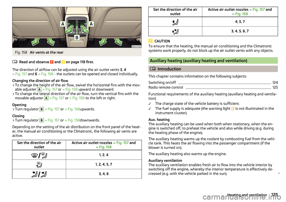
Fig. 158
Air vents at the rear
Read and observe
and on page 119 first.
The direction of airflow can be adjusted using the air outlet vents 3, 4
» Fig. 157 and 6 » Fig. 158 - the outlets can be opened and closed individually.
Changing the direction of air flow
›
To change the height of the air flow, swivel the horizontal fins with the mov-
able adjuster
A
» Fig. 157 or » Fig. 158 upward or downward.
›
To change the lateral direction of the air flow, turn the vertical fins with the
movable adjuster
A
» Fig. 157 or » Fig. 158 to the left or right.
Opening
›
Turn regulator
B
» Fig. 157 or » Fig. 158 upwards.
Closing
›
Turn regulator
B
» Fig. 157 or » Fig. 158 downwards.
Depending on the setting of the air distribution on the front panel of the heat-
er, the manual air conditioning or the Climatronic, the following air vents are
active.
Set the direction of the air outletActive air outlet nozzles » Fig. 157 and
» Fig. 158 1, 2 , 41, 2 , 4 , 5 , 7 3, 4 , 6Set the direction of the air
outletActive air outlet nozzles » Fig. 157 and
» Fig. 1584 , 5 , 73 , 4 , 5 , 6 , 7
CAUTION
To ensure that the heating, the manual air conditioning and the Climatronic
systems work properly, do not block up the air outlet vents with any objects.
Auxiliary heating (auxiliary heating and ventilation)
Introduction
This chapter contains information on the following subjects:
Switching on/off
124
Radio remote control
125
Functional requirements of the auxiliary heating (auxiliary heating and ventila-
tion)
The charge state of the vehicle battery is sufficient.
The fuel supply is adequate (the warning light is not illuminated in the
instrument cluster).
Aux. heating
The auxiliary heating can be used when both when stationary, when the en-
gine is switched off, to preheat the vehicle and also while driving (e.g. during
the heating phase of the engine).
The auxiliary heating warms up the coolant by combusting fuel from the vehi-
cle tank. This heats the air flowing into the passenger compartment (if the
blower is turned on).
The auxiliary heating also warms up the engine.
Auxiliary ventilation
The auxiliary ventilation enables fresh air to flow into the vehicle interior by
switching off the engine, whereby the interior temperature is effectively de-
creased (e.g. with the vehicle parked in the sun).
123Heating and ventilation