fuel type SKODA SUPERB 2015 3.G / (B8/3V) Owner's Manual
[x] Cancel search | Manufacturer: SKODA, Model Year: 2015, Model line: SUPERB, Model: SKODA SUPERB 2015 3.G / (B8/3V)Pages: 276, PDF Size: 42.14 MB
Page 5 of 276
Traffic jam assistant179Assistant for emergencies179
Traffic sign recognition
180
Fatigue detection
182
Tyre pressure monitoring
183
Hitch and trailer
184
Hitch
184
Trailer
185
General Maintenance
Care and maintenance
190
Service work, adjustments and technical
alterations
190
Washing vehicle
193
Cleaning vehicle exterior
194
Interior care
198
Inspecting and replenishing
201
Fuel
201
AdBlue ®
and its refilling
204
Engine compartment
206
Engine oil
209
Coolant
210
Brake fluid
212
Vehicle battery
213
Wheels
217
Tyres and wheel rims
217
Winter operation
220
Do-it-yourself
Emergency equipment and self-help
222
Emergency equipment
222
Changing a wheel
224
Puncture repair kit
228
Jump-starting
230
Towing the vehicle
231
Remote control and removable light
233Emergency unlocking/locking235Replacing windscreen wiper blades237
Fuses and light bulbs
238
Fuses
238
Bulbs
242
Technical data
Technical data
246
Basic vehicle data
246
Vehicle-specific information depending on
engine type
252
Index
3Table of Contents
Page 17 of 276
System descriptionRead and observe
on page 14 first.
The inflation of the airbag is carried out in a fraction of a second.
When the airbags are deployed, they fill with gas and inflate.
A grey white or red, non-harmful gas is released when the airbag is inflated.
This is perfectly normal and is not an indication of a fire in the vehicle.
Depending on the vehicle equipment, the airbag system consists of the
following parts. ▶ Front airbag for the driver and the front passenger » page 15.
▶ Driver’s knee airbag » page 17.
▶ Side airbags » page 17.
▶ Head airbags » page 18.
▶ Airbag warning light in the instrument cluster » page 35.
▶ Key switch for the front passenger airbag » page 19.
▶ Warning light for the front passenger airbag in the middle of the dash panel
» page 19 .
Airbag deployment
Read and observe
on page 14 first.
The airbag system is only functional when the ignition is switched on.
Triggering conditions
It is not possible to generally determine which deployment conditions apply to
the airbag system in every situation. An important role is played by factors
such as the type of object that the vehicle hits (hard/soft), the impact angle, vehicle speed etc.
A decisive factor for the deployment of the airbags is the deceleration which
occurs. If the vehicle deceleration which occurs and is measured during the
collision remains below the prescribed reference values specified in the control
unit, the airbags are not deployed although the vehicle may well suffer severe
damage to the bodywork as a consequence of the accident.
The following airbags will be deployed in the event of a severe frontal
collision.
▶ Driver’s front airbag.
▶ Front passenger airbag.
▶ Driver’s knee airbag.
The following airbags will be deployed in the event of a severe side collision.
▶ Front side airbag on the side of the accident.
▶ Rear side airbag on the side of the accident.
▶ Head airbags on the side of the accident.
When an airbag is deployed, the following events occur. ▶ The interior light comes on (if the automatic operation of the interior light is
switched on - switch
).
▶ The hazard warning lights are switched on.
▶ All doors are unlocked.
▶ The fuel supply to the engine is interrupted.
When there is no air bag deployment?
With minor frontal and side collisions, rear collision, overturning of the vehicle
or vehicle roll-over there is no airbag deployment.
Airbag overview
Introduction
This chapter contains information on the following subjects:
Front airbags
15
Driver’s knee airbag
17
Side airbags
17
Head airbags
18
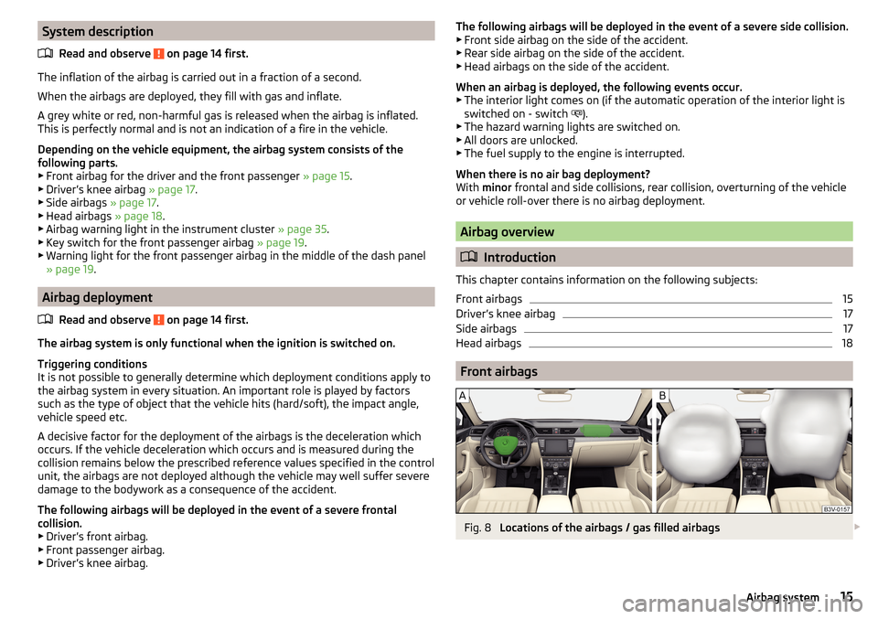
Front airbags
Fig. 8
Locations of the airbags / gas filled airbags
15Airbag system
Page 31 of 276
OverviewFig. 22
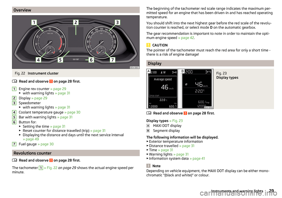
Instrument cluster
Read and observe
on page 28 first.
Engine rev counter » page 29
▶ with warning lights » page 31
Display » page 29
Speedometer
▶ with warning lights » page 31
Coolant temperature gauge » page 30
Bar with warning lights » page 31
Button for: ▶ Setting the time » page 31
▶ Reset counter for distance travelled (trip) » page 31
▶ Displaying the distance and days until the next service interval
» page 49
Fuel gauge » page 30
Revolutions counter
Read and observe
on page 28 first.
The tachometer
1
» Fig. 22 on page 29 shows the actual engine speed per
minute.
1234567The beginning of the tachometer red scale range indicates the maximum per-
mitted speed for an engine that has been driven-in and has reached operating
temperature.
You should shift into the next highest gear before the red scale of the revolu-
tion counter is reached, or select mode D on the automatic gearbox.
The gear recommendation is important to note in order to maintain the opti-
mum engine speed » page 42.
CAUTION
The pointer of the tachometer must reach the red area for only a short time -
there is a risk of engine damage!
Display
Fig. 23
Display types
Read and observe on page 28 first.
Display types » Fig. 23
MAXI DOT display
Segment display
The following information will be displayed.
▶ Exterior temperature information
▶ Distance travelled » page 31
▶ Time » page 31
▶ Warning lights » page 31
▶ Information system data » page 41
Note
Depending on vehicle equipment, the MAXI DOT display can be either mono-
chromatic “(black and white)” or colour.29Instruments and warning lights
Page 142 of 276

DriveGreen functionFig. 172
Shown in the infotainment dis-
play
The DriveGreen function (hereinafter referred to as DriveGreen) evaluates the
driving efficiency based on the information respecting the driving style. Useful
tips for reducing fuel consumption are also offered.
DriveGreen can be displayed on the Infotainment as follows.
›
Press the button in the Infotainment and then in the display the function
keys one after the other
→
DriveGreen
.
A
driving liquid display
With the driving is liquid the display is near the green dot. When accelerating
or braking, the indicator moves down or up.
B
“Green leaf”
The leaf margin shown in green shows with a few seconds, the current drive
efficiency. When driving economically there are several green layers on the
edge of the leaf. If driving less economically, no green colour appears and the
leaf can disappear completely.
C
Graphical review summary
The evaluation of the driving economy during the last 3 minutes or 1.5 minutes
(depending on type of Infotainment) is shown like a beam in 5-second incre-
ments. The current status is shown on the left and moves gradually to the
right. The higher the green bars, the more economic the driving style is.
D
Scoring
In the function key, the evaluation of driving efficiency is shown from the start
in the range from 0 to 100 points. The higher the indicated value, the more
economic the driving style is.
When you press the function key, a detailed assessment showing the driving
efficiency during the last 30 minutes is shown.
If the trip from the start, takes less than 30 minutes, then the assessment
takes in information from the previous trip (the bars are shown in dark green).E
Average fuel consumption
In the function key, the average fuel consumption from the start is displayed.
When you press the function key a detailed overview of the average fuel con-
sumption during the last 30 minutes is shown.
If the trip from the start, takes less than 30 minutes, then the average fuel
consumption takes in information from the previous trip (the bars are shown in
dark green).
F
Symbols in the display
The display may show the following four symbols, which give information on
the current driving style.
Ecological trip
The current speed has a negative effect on fuel consumption. The driving is not liquid, drive with anticipation.
Recommended gear.
Tips for reducing fuel consumption
When tapping the “Page” the display shows useful tips on how to reduce fuel consumption. These tips can to be helpful to drive more economically.
Note
■ Resetting the single-trip memory “from start” also resets the average con-
sumption E and the driving assessment D.■
With some Infotainment types changing the units for the fuel consumption
indicator causes the resetting of the average fuel consumption values
E
.
Radiator blind
The radiator blind(hereinafter: blind) helps to reduce CO 2emissions as well as
harmful emissions and to save fuel.
If the system detects that it is possible to reduce the amount of air flowing to
the radiator, it closes the blinds. As a result the wind resistance at the front of
the vehicle is reduced.
The blinds are located between the grille in the front bumper and the radiator.
140Driving
Page 203 of 276
Inspecting and replenishing
Fuel
Introduction
This chapter contains information on the following subjects:
Petrol and diesel refuelling
201
Lead-free petrol
202
Diesel fuel
203
The correct fuel grades for your vehicle are specified on the inside of the fuel
filler flap » Fig. 224 on page 201 .
WARNING■
The operating instructions of the refuelling system must always be fol-
lowed.■
Do not smoke when refuelling and do not use a mobile phone.
■
Fuel vapours are explosive - can be fatal!
CAUTION
■ Never drive until the fuel tank is completely empty! The irregular supply of
fuel can cause misfiring, which can result in damage to parts of the engine and
the exhaust system.■
Immediately remove any fuel that has spilled onto the vehicle's paintwork –
risk of paint damage.
■
If the vehicle was not purchased in the country where it was intended to be
operated, you should check whether the fuel specified by the manufacturer is
offered in the country where the vehicle will be operated. You should also per-
haps check whether the manufacturer has recommended a different fuel for
operation of the vehicle in the corresponding country. If no prescribed fuel is
available, then you must check whether it is permitted by the manufacturer to
operate the vehicle with another fuel type.
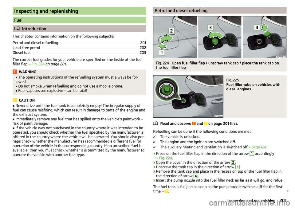
Petrol and diesel refuellingFig. 224
Open fuel filler flap / unscrew tank cap / place the tank cap on
the fuel filler flap
Fig. 225
Fuel filler tube on vehicles with
diesel engines
Read and observe and on page 201 first.
Refuelling can be done if the following conditions are met.
The vehicle is unlocked.
The engine and the ignition are switched off.
The auxiliary heating and ventilation is switched off » page 124.
›
Press on the fuel filler flap in the direction of the arrow
1
accordingly
» Fig. 224 .
›
Open the cover in the direction of the arrow
2
.
›
Unscrew the tank cap in the direction of arrow
3
.
›
Remove the tank cap and place in the recess on top of the fuel filler flap in
the direction of arrow
4
.
›
Insert the pump nozzle into the fuel filler neck as far as it will go, and refuel.
The fuel tank is full just as soon as the pump nozzle switches off for the first
time »
.
201Inspecting and replenishing
Page 248 of 276

Technical data
Technical data
Basic vehicle data
Introduction
This chapter contains information on the following subjects:
Vehicle characteristics
246
Operating weight
247
Payload
248
Measurement of fuel consumption and CO 2 emissions according to ECE
Regulations and EU Directives
248
Dimensions - Superb
249
Dimensions - Superb estate
250
Overhang angle
251
The details given in the vehicle's technical documentation always take prece-
dence over the details in the Owner's Manual.
The listed performance values were determined without performance-reduc- ing equipment, e.g. air conditioning system.
The values given have been determined in accordance with the rules and con-
ditions specified in statutory or technical regulations for determining opera-
tional and technical data for motor vehicles.
The values listed are for the basic model without any optional equipment.
Vehicle characteristicsFig. 277
Vehicle data sticker/type plate
Vehicle data sticker
The vehicle data sticker » Fig. 277 -
is located on the base of the luggage
compartment and is also fixed into the service schedule.
The vehicle data sticker contains the following data. Vehicle identification number (VIN)
Vehicle type
Gearbox code/paint number/interior equipment/engine output/engine code
Partial vehicle description
Approved tyre diameter in inches 1)
The approved tyres and rim sizes for your vehicle are listed in the vehicle's
technical documentation (the so called COC document) and this also states the
declaration of conformity.
Type plate
The type plate » Fig. 277 -
is located at the bottom of the B-pillar on the
right driver's side.
The type plate contains the following data. Manufacturer
Vehicle identification number (VIN)
Maximum permissible gross weight
Maximum permissible towed weight (towing vehicle and trailer)
1234567891)
Only valid for some countries.
246Technical data
Page 249 of 276
Maximum permissible front axle load
Maximum permissible rear axle load
Vehicle identification number (VIN)
The vehicle identification number - VIN (vehicle body number) is stamped into
the engine compartment on the right hand suspension strut dome. This num-
ber is also located on a sign on the lower left hand edge below the windscreen
(together with a VIN bar code), and on the type plate.
The VIN number can also be displayed in the Infotainment » Owner´s Manual
Infotainment , chapter CAR - vehicle settings .
Engine number
The engine number (three-digit identifier and serial number) is stamped on the
engine block.
Supplementary Information (applies to Russia)
The full type approval number of the means of transport is indicated in the
registration documents, field 17.
Maximum permissible towed weight
The listed maximum allowable trailer weight is only valid for altitudes up to
1000 m above sea level.
The engine output falls as altitude increases, as does the vehicle's climbing
power. Therefore, for every additional 1000 m in height (or part), the maximum
permissible towed weight must be reduced by 10%.
The towed weight is made up of the actual weights of the loaded towing vehi-
cle and the loaded trailer.WARNINGDo not exceed the specified maximum permissible weights – risk of acci-
dent and damage!
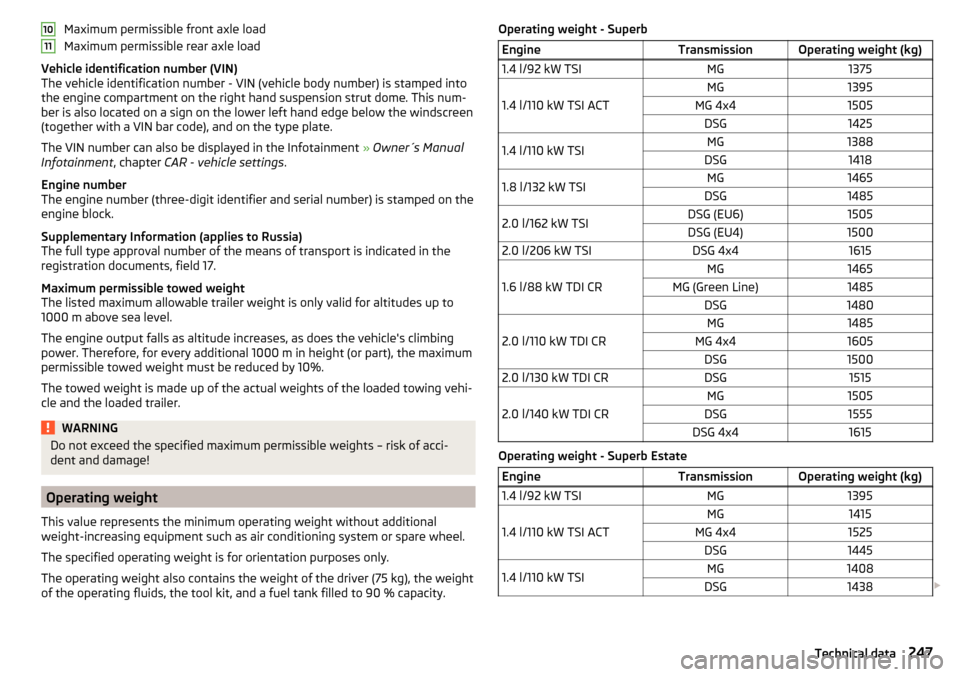
Operating weight
This value represents the minimum operating weight without additional
weight-increasing equipment such as air conditioning system or spare wheel.
The specified operating weight is for orientation purposes only.
The operating weight also contains the weight of the driver (75 kg), the weight
of the operating fluids, the tool kit, and a fuel tank filled to 90 % capacity.
1011Operating weight - SuperbEngineTransmissionOperating weight (kg)1.4 l/92 kW TSIMG1375
1.4 l/110 kW TSI ACT
MG1395MG 4x41505DSG14251.4 l/110 kW TSIMG1388DSG14181.8 l/132 kW TSIMG1465DSG14852.0 l/162 kW TSIDSG (EU6)1505DSG (EU4)15002.0 l/206 kW TSIDSG 4x41615
1.6 l/88 kW TDI CR
MG1465MG (Green Line)1485DSG1480
2.0 l/110 kW TDI CR
MG1485MG 4x41605DSG15002.0 l/130 kW TDI CRDSG1515
2.0 l/140 kW TDI CR
MG1505DSG1555DSG 4x41615
Operating weight - Superb Estate
EngineTransmissionOperating weight (kg)1.4 l/92 kW TSIMG1395
1.4 l/110 kW TSI ACT
MG1415MG 4x41525DSG14451.4 l/110 kW TSIMG1408DSG1438 247Technical data