brake sensor SKODA SUPERB 2016 3.G / (B8/3V) Owner's Manual
[x] Cancel search | Manufacturer: SKODA, Model Year: 2016, Model line: SUPERB, Model: SKODA SUPERB 2016 3.G / (B8/3V)Pages: 336, PDF Size: 53.89 MB
Page 64 of 336
›To
open/close , move one foot in the sensor area below the rear bumper
quickly in the direction of the arrow » Fig. 42.
The brake light in the rear window illuminates and the lid opens/closes auto-
matically. An acoustic signal is sounded when opening/closing the lid.
If the lid does not move, then repeat the operating process after a few sec-
onds.
The lid movement can be stopped by a rapid swinging of the foot. Swinging
the foot again will continue the lid movement.
The function can be activated / deactivated in Infotainment in the menu
→
→
Opening and closing
.
We recommend that the function is deactivated in the following cases:
▶ Installation of a roof rack.
▶ Connecting a trailer (accessory) to the towbar.
▶ Manual vehicle wash.
▶ Maintenance and repair work in the back of the vehicle.
When connecting a device to the trailer socket the deactivation of the function
takes place.
Note
With heavy rain or a dirty rear bumper, under certain circumstances that there
may be limitations, or the automatic deactivation of the contactless opening
function of the boot lid may occur.
Window operation
Introduction
This chapter contains information on the following subjects:
Open / close Window
62
Force limiter
63
Window convenience operation
63
Malfunctions
64
The windows in the doors can be operated electrically using the buttons on
the doors.
WARNING■ Always close the window carefully and controlled. Doing so may may
cause yourself or fellow passengers considerable crushing injuries.■
The system is fitted with a force limiter » page 63. If there is an obstacle
(e.g. In the event of a body part becoming trapped) the closing process is
stopped and the window goes down by several centimetres. However, the
windows should be closed carefully – risk of injury.
CAUTION
■ Keep the windows clean to ensure the correct functionality of the electric
power windows.■
Always close the windows before disconnecting the battery.
Note
If the windows are opened, dust and other dirt can get into the vehicle and the
wind noise is more at certain speeds.
Open / close Window
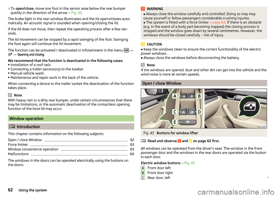
Fig. 43
Buttons for window lifter
Read and observe
and on page 62 first.
All windows can be operated from the driver's seat. The window in the front
passenger door and the windows in the rear doors are operated via the button
in each door.
Electric window buttons » Fig. 43
Front door left
Front door right
Rear door, left
ABC62Using the system
Page 217 of 336
Multicollision brake (MCB)Read and observe
on page 213 first.
MCB helps to decrease speed after a collision by means of automatic braking
interventions and to stabilise the vehicle. This reduces the risk of a subse-
quent crash due to uncontrolled vehicle movement.
The automatic brake interventions can take place only if the following condi-
tions are met.
There was a front, side and rear-end collision of a certain severity.
The impact speed was greater than approx. 10 km/h.
The brakes, the ESL and other required electrical systems remain function-
al after impact.
The accelerator pedal is not actuated.
Trailer stabilisation system (TSA)
Read and observe
on page 213 first.
The TSA helps the combination stable in situations where the trailer sways
and then the whole trailer combination.
TSA brakes the individual wheels of the towing vehicle in order to damp the rocking motion of the entire vehicle combination.
The following conditions are required for the correct TSA function. The trailer was shipped from the factory or purchased from the ŠKODA
genuine accessories.
The trailer is electrically connected to the towing vehicle via the trailer
socket.
The parking aid is activated.
The speed is greater than 60 km/h.
Further information » page 250, Towing device and trailer .
Parking aid (ParkPilot)
Introduction
This chapter contains information on the following subjects:
Settings in Infotainment
216
Operation
216
Display in Infotainment screen
217
Activation / deactivation
217
Automatic system activation when moving forward
218
The parking aid (hereinafter referred to as system) uses acoustic signals or the
Infotainment screen when manoeuvring around obstacles in the vicinity of the
vehicle.
WARNING■ The general information relating to the use of assistance systems must
be observed » page 212, in section Introduction .■
Moving persons or objects may not be recognized by the system sensors.
■
Under certain circumstances, surfaces of certain objects and types of
clothing cannot reflect the system signals. There is a danger that such ob-
jects or people may not be recognised by the system sensors.
■
External noise sources may affect the signals of the system sensors.
There is a danger that obstacles may not be detected by the system sen-
sors.
■
Before reversing, you should satisfy yourself that there are no small ob-
stacle, such as a rock, thin post etc., in front or behind your vehicle. Such
obstacles may not be recognised by the system sensors.
CAUTION
■ Keep the system sensors » Fig. 266 on page 216 clean, snow-and ice-free
and do not cover with any objects of any kind, otherwise the system function-
ing may be impaired.■
Under adverse weather conditions (heavy rain, water vapour, very low or
high temperatures, etc.), the system function may be limited - “incorrect recog-
nition of obstacle”.
■
Accessories fitted to the vehicle rear, such as bicycle carriers, can impair the
system function.
215Assist systems
Page 227 of 336
›Stop the vehicle and steer opposite until the yellow lines 6 the red line 8fade into each other (required roadway alignment). Hold the steering wheel
in this position.
Orientation lines are displayed » Fig. 278 on page 223 on the screen.›
Carefully move backwards.
›
Stop the vehicle when
appears on the screen, or at a safe distance from
the obstacle situated behind the vehicle.
Note
The guidance in the parking space is cancelled due to the system when the
steering wheel is set for a period of time against the required road direction.
The parking is to be started again.
mode- Driving up to a trailer / Distance monitoring
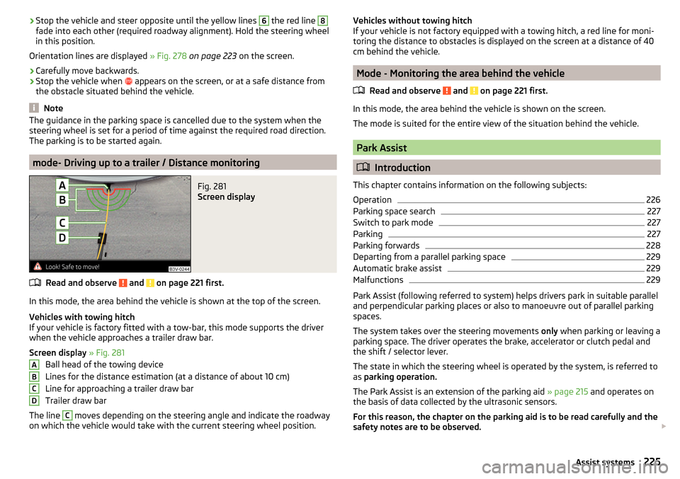
Fig. 281
Screen display
Read and observe and on page 221 first.
In this mode, the area behind the vehicle is shown at the top of the screen.
Vehicles with towing hitch
If your vehicle is factory fitted with a tow-bar, this mode supports the driver
when the vehicle approaches a trailer draw bar.
Screen display » Fig. 281
Ball head of the towing device
Lines for the distance estimation (at a distance of about 10 cm)
Line for approaching a trailer draw bar
Trailer draw bar
The line
C
moves depending on the steering angle and indicate the roadway
on which the vehicle would take with the current steering wheel position.
ABCDVehicles without towing hitch
If your vehicle is not factory equipped with a towing hitch, a red line for moni-
toring the distance to obstacles is displayed on the screen at a distance of 40
cm behind the vehicle.
Mode - Monitoring the area behind the vehicle
Read and observe
and on page 221 first.
In this mode, the area behind the vehicle is shown on the screen.
The mode is suited for the entire view of the situation behind the vehicle.
Park Assist
Introduction
This chapter contains information on the following subjects:
Operation
226
Parking space search
227
Switch to park mode
227
Parking
227
Parking forwards
228
Departing from a parallel parking space
229
Automatic brake assist
229
Malfunctions
229
Park Assist (following referred to system) helps drivers park in suitable parallel
and perpendicular parking places or also to manoeuvre out of parallel parking
spaces.
The system takes over the steering movements only when parking or leaving a
parking space. The driver operates the brake, accelerator or clutch pedal and
the shift / selector lever.
The state in which the steering wheel is operated by the system, is referred to
as parking operation.
The Park Assist is an extension of the parking aid » page 215 and operates on
the basis of data collected by the ultrasonic sensors.
For this reason, the chapter on the parking aid is to be read carefully and the safety notes are to be observed.
225Assist systems
Page 235 of 336
Adaptive Cruise Control (ACC)
Introduction
This chapter contains information on the following subjects:
Settings in Infotainment
233
Operation
234
Automatic stopping and starting
234
Operation overview
235
Start control
235
Stop/resume control
235
Set/change the desired speed
236
Set the clearance level
236
Special driving situations
236
Overtaking and towing
237
Malfunctions
237
The Adaptive Cruise Control (hereinafter referred to as ACC) maintains the set
speed or the distance to the vehicle ahead without the accelerator or brake
pedal being pressed.
The front of the vehicle and the distance to the vehicle ahead is monitored by
a radar sensor » page 212.
The state in which the ACC maintains the speed or the proximity is described
as control from here on.
WARNING■
The general information relating to the use of assistance systems must
be observed » page 212, in section Introduction .■
The driver must always be ready to take over the operation of the accel-
erator and brake pedal.
■
The ACC does not react when approaching a stationary obstacle, such as
traffic jams, vehicle breakdowns or vehicles waiting at a traffic light.
■
The ACC does not respond to crossing or oncoming objects.
■
If the ACC does not decelerate fast enough, immediately apply the vehi-
cle's foot brake.
WARNINGFor safety reasons, do not use the ACC under the following conditions.■When driving in turning lanes, motorway exits or construction sites, to
avoid an unwanted acceleration to the stored speed.■
When visibility is poor, (e.g. fog, heavy rain, thick snowfall).
■
When road conditions are poor (e.g. ice, slippery road, gravel, dirt road).
■
Driving in “sharp” corners or in steep gradients / on steep inclines.
■
When driving through places where metal objects (such as metal build-
ings, railway tracks, etc.) can be found.
■
When driving through very divided and enclosed spaces (such as large-ca-
pacity garages, car ferries, tunnels and the like.).
Note
■ The ACC is designed primarily for use on motorways.■The ACC reduces the speed by automatically releasing the accelerator or by
means of a braking procedure as appropriate. If the brakes are used for an au-
tomatic speed reduction at any moments, then the brake light illuminates.■
In case of failure of more than one brake light on the vehicle or on the con-
nected trailer, the ACC becomes unavailable.
■
The control automatically cancels the engagement of the brake supportive
assistance systems (e.g. ESC) or when the maximum permitted engine speed is
exceeded.
Settings in Infotainment
Read and observe
on page 233 first.
›
Press the button, then tap on the function surface
→
Driver assistance
.
■ ACC (adaptive cruise control) - Setting for the adaptive cruise control
■
Driving progr.:
- Set the vehicle acceleration when adaptive cruise control is
activated 1)
■
Last selec. Distance
- Switch on/off of the last distance selected
■
Distance:
- Set the distance monitoring to the vehicles ahead
1)
This can be set in the menu on vehicles with a travel mode option as follows » page 240 .
233Assist systems
Page 236 of 336
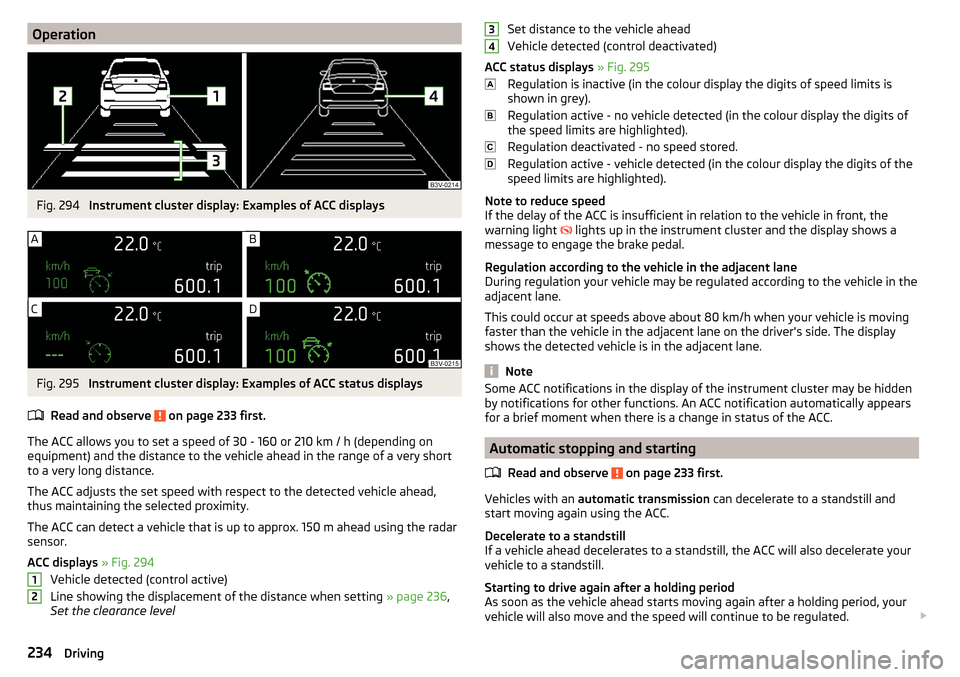
OperationFig. 294
Instrument cluster display: Examples of ACC displays
Fig. 295
Instrument cluster display: Examples of ACC status displays
Read and observe
on page 233 first.
The ACC allows you to set a speed of 30 - 160 or 210 km / h (depending on
equipment) and the distance to the vehicle ahead in the range of a very short
to a very long distance.
The ACC adjusts the set speed with respect to the detected vehicle ahead,
thus maintaining the selected proximity.
The ACC can detect a vehicle that is up to approx. 150 m ahead using the radar
sensor.
ACC displays » Fig. 294
Vehicle detected (control active)
Line showing the displacement of the distance when setting » page 236,
Set the clearance level
12Set distance to the vehicle ahead
Vehicle detected (control deactivated)
ACC status displays » Fig. 295
Regulation is inactive (in the colour display the digits of speed limits is
shown in grey).
Regulation active - no vehicle detected (in the colour display the digits of
the speed limits are highlighted).
Regulation deactivated - no speed stored.
Regulation active - vehicle detected (in the colour display the digits of the
speed limits are highlighted).
Note to reduce speed
If the delay of the ACC is insufficient in relation to the vehicle in front, the
warning light lights up in the instrument cluster and the display shows a
message to engage the brake pedal.
Regulation according to the vehicle in the adjacent lane
During regulation your vehicle may be regulated according to the vehicle in the
adjacent lane.
This could occur at speeds above about 80 km/h when your vehicle is moving
faster than the vehicle in the adjacent lane on the driver's side. The display
shows the detected vehicle is in the adjacent lane.
Note
Some ACC notifications in the display of the instrument cluster may be hidden
by notifications for other functions. An ACC notification automatically appears
for a brief moment when there is a change in status of the ACC.
Automatic stopping and starting
Read and observe
on page 233 first.
Vehicles with an automatic transmission can decelerate to a standstill and
start moving again using the ACC.
Decelerate to a standstill
If a vehicle ahead decelerates to a standstill, the ACC will also decelerate your
vehicle to a standstill.
Starting to drive again after a holding period
As soon as the vehicle ahead starts moving again after a holding period, your
vehicle will also move and the speed will continue to be regulated.
34234Driving
Page 239 of 336
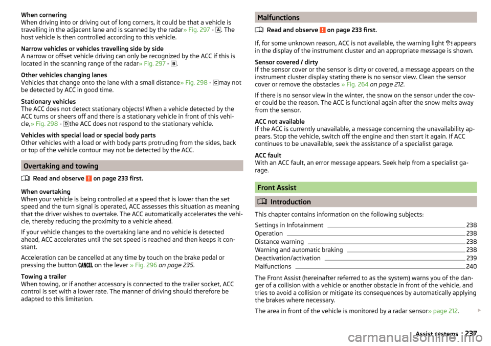
When cornering
When driving into or driving out of long corners, it could be that a vehicle is
travelling in the adjacent lane and is scanned by the radar » Fig. 297 -
. The
host vehicle is then controlled according to this vehicle.
Narrow vehicles or vehicles travelling side by side
A narrow or offset vehicle driving can only be recognized by the ACC if this is
located in the scanning range of the radar » Fig. 297 -
.
Other vehicles changing lanes
Vehicles that change onto the lane with a small distance » Fig. 298 -
may not
be detected by ACC in good time.
Stationary vehicles
The ACC does not detect stationary objects! When a vehicle detected by the
ACC turns or sheers off and there is a stationary vehicle in front of this vehi-
cle, » Fig. 298 -
the ACC does not respond to the stationary vehicle.
Vehicles with special load or special body parts
Other vehicles with a load or with body parts protruding from the sides, back
or top of the vehicle contour may not be detected by the ACC.
Overtaking and towing
Read and observe
on page 233 first.
When overtaking
When your vehicle is being controlled at a speed that is lower than the set
speed and the turn signal is operated, ACC assesses this situation as meaning
that the driver wishes to overtake. The ACC automatically accelerates the vehi-
cle, thereby reducing the proximity to a vehicle ahead.
If your vehicle changes to the overtaking lane and no vehicle is detected
ahead, ACC accelerates until the set speed is reached and then keeps it con-
stant.
Acceleration can be cancelled at any time by touch on the brake pedal or
pressing the button on the lever
» Fig. 296 on page 235 .
Towing a trailer
When towing, or if another accessory is connected to the trailer socket, ACC
control is set with a lower rate. The manner of driving should therefore be
adapted to this limitation.
Malfunctions
Read and observe
on page 233 first.
If, for some unknown reason, ACC is not available, the warning light
appears
in the display of the instrument cluster and an appropriate message is shown.
Sensor covered / dirty
If the sensor cover or the sensor is dirty or covered, a message appears on the
instrument cluster display stating there is no sensor view. Clean the sensor
cover or remove the obstacles » Fig. 264 on page 212 .
If there is no sensor view in the winter, the snow on the sensor under the cov- er could be the reason. The ACC is functional again after the snow melts away
from the sensor.
ACC not available
If the ACC is currently unavailable, a message concerning the unavailability ap-
pears. Stop the vehicle, switch off the engine and then start it again. If ACC
continues to be unavailable, seek the assistance of a specialist garage.
ACC fault
With an ACC fault, an error message appears. Seek help from a specialist ga-
rage.
Front Assist
Introduction
This chapter contains information on the following subjects:
Settings in Infotainment
238
Operation
238
Distance warning
238
Warning and automatic braking
238
Deactivation/activation
239
Malfunctions
240
The Front Assist (hereinafter referred to as the system) warns you of the dan-
ger of a collision with a vehicle or another obstacle in front of the vehicle, and
tries to avoid a collision or mitigate its consequences by automatically applying
the brakes where necessary.
The area in front of the vehicle is monitored by a radar sensor » page 212.
237Assist systems
Page 247 of 336
Activation / deactivationRead and observe
and on page 243 first.
The activation/deactivation of the system can be carried out in one of two
ways. ▶ In the instrument cluster display » page 48, Menu item
Assist systems
.
▶ In Infotainment » page 243, Settings in Infotainment .
Adaptive tracking can also be enabled or disabled In Infotainment.
After switching off and switching on the ignition, the system setting is re-
tained.
Note
The system setting is stored (depending on the Infotainment type) in the ac-
tive user account personalisation » page 49.
Malfunctions
Read and observe
and on page 243 first.
If, for some unknown reason, the system is not available, an appropriate mes-
sage appears in the display of the instrument cluster.
Sensor covered / dirty
If the windscreen is dirty, iced or misted up in the sensor area, a message ap-
pears indicating that there is no sensor view. Clean the windscreen or remove
the obstacles from the sensor area.
System unavailable
If the system is currently unavailable, a message concerning the unavailability
appears. Try to re-activate the machine. If the system still is not available, seek
the assistance of a specialist garage.
System fault
In the case of a system fault, an error message appears. Seek help from a spe-
cialist garage.
Request to take over steering
If the system detects that there are no hands are on the steering wheel, this
will not work properly. You will be prompted to take over steering. Place your
hands on the steering wheel.
Traffic jam assistant
Introduction
This chapter contains information on the following subjects:
Function
245
Operating conditions
245WARNING■ Please take note of the general points relating to the use of assistance
systems » page 212, in section Introduction .■
The driver must always have hands on the steering wheel and be ready to
take over steering of the vehicle himself (accelerate or brake).
Note
The system is designed primarily for use on motorways.
Function
Read and observe
on page 245 first.
The traffic jam assistant (referred to as system) helps to keep the vehicle with-
in the lane at speeds below 65 km/h while keeping the distance to the vehicle
ahead.
The system is only available for vehicles with Automatic transmission.
The traffic jam assistant is an extension of the systems Lane Assist » page 243
and ACC » page 233 and works by using the functions of these two systems.
For this reason, the chapters on System Lane Assist and ACC are to be read
carefully and the safety notes are to be observed.
Operating conditions
Read and observe
on page 245 first.
The system activation occurs automatically whilst fulfilling the following ba-sic conditions.
Lane Assist with the adaptive tracking is enabled, the boundary lines on
both sides are recognized lane » page 243.
ACC is activated and the regulation » page 233 follows.
The vehicle speed is below 65 km/h.
245Assist systems
Page 299 of 336
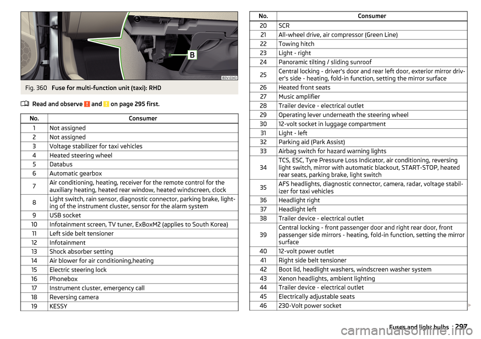
Fig. 360
Fuse for multi-function unit (taxi): RHD
Read and observe
and on page 295 first.
No.Consumer1Not assigned2Not assigned3Voltage stabilizer for taxi vehicles4Heated steering wheel5Databus6Automatic gearbox7Air conditioning, heating, receiver for the remote control for the
auxiliary heating, heated rear window, heated windscreen, clock8Light switch, rain sensor, diagnostic connector, parking brake, light-
ing of the instrument cluster, sensor for the alarm system9USB socket10Infotainment screen, TV tuner, ExBoxM2 (applies to South Korea)11Left side belt tensioner12Infotainment13Shock absorber setting14Air blower for air conditioning,heating15Electric steering lock16Phonebox17Instrument cluster, emergency call18Reversing camera19KESSYNo.Consumer20SCR21All-wheel drive, air compressor (Green Line)22Towing hitch23Light - right24Panoramic tilting / sliding sunroof25Central locking - driver's door and rear left door, exterior mirror driv-
er's side - heating, fold-in function, setting the mirror surface26Heated front seats27Music amplifier28Trailer device - electrical outlet29Operating lever underneath the steering wheel3012-volt socket in luggage compartment31Light - left32Parking aid (Park Assist)33Airbag switch for hazard warning lights34TCS, ESC, Tyre Pressure Loss Indicator, air conditioning, reversing
light switch, mirror with automatic blackout, START-STOP, heated
rear seats, parking brake, light switch35AFS headlights, diagnostic connector, camera, radar, voltage stabil-
izer for taxi vehicles36Headlight right37Headlight left38Trailer device - electrical outlet39Central locking - front passenger door and right rear door, front
passenger side mirrors - heating, fold-in function, setting the mirror
surface4012-volt power outlet41Right side belt tensioner42Boot lid, headlight washers, windscreen washer system43Xenon headlights, ambient lighting44Trailer device - electrical outlet45Electrically adjustable seats46230-Volt power socket 297Fuses and light bulbs
Page 300 of 336
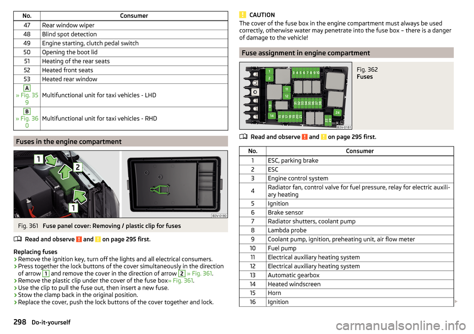
No.Consumer47Rear window wiper48Blind spot detection49Engine starting, clutch pedal switch50Opening the boot lid51Heating of the rear seats52Heated front seats53Heated rear windowA
» Fig. 359Multifunctional unit for taxi vehicles - LHD
B
» Fig. 36 0Multifunctional unit for taxi vehicles - RHD
Fuses in the engine compartment
Fig. 361
Fuse panel cover: Removing / plastic clip for fuses
Read and observe
and on page 295 first.
Replacing fuses
›
Remove the ignition key, turn off the lights and all electrical consumers.
›
Press together the lock buttons of the cover simultaneously in the direction
of arrow
1
and remove the cover in the direction of arrow
2
» Fig. 361 .
›
Remove the plastic clip under the cover of the fuse box » Fig. 361.
›
Use the clip to pull the fuse out, then insert a new fuse.
›
Stow the clamp back in the original position.
›
Replace the cover, push the lock buttons of the cover together and lock.
CAUTIONThe cover of the fuse box in the engine compartment must always be used
correctly, otherwise water may penetrate into the fuse box – there is a danger
of damage to the vehicle!
Fuse assignment in engine compartment
Fig. 362
Fuses
Read and observe and on page 295 first.
No.Consumer1ESC, parking brake2ESC3Engine control system4Radiator fan, control valve for fuel pressure, relay for electric auxili-
ary heating5Ignition6Brake sensor7Radiator shutters, coolant pump8Lambda probe9Coolant pump, ignition, preheating unit, air flow meter10Fuel pump11Electrical auxiliary heating system12Electrical auxiliary heating system13Automatic gearbox14Heated windscreen15Horn16Ignition 298Do-it-yourself
Page 323 of 336
Route schedule192
Search for destination182
Set to137
Start the route guidance190
Status line138
Tank options138
Top speeds138
Traffic jam ahead197
Traffic reports (TMC)196
Trailer towing191
Transit point193
Update navigation data181
Update the navigation data138
Version information138
Voice control128
Waypoint mode194
Navigation data181
Nav. announcements138, 192
Net partition111
Nets102, 103
Network Data connection
133
Data roaming133
Set133
set to136
Values of the downloaded data133
New route194
O
oil see Engine oil
271
Oil Information messages
40
Oil changing Engine oil
270
On-board computer see multifunction display
46
Online Owner's Manual8
Operating weight304
Operation Media146
MirrorLink®179
Radio142
Telephone162, 163
Original accessories257
Overhang angle308
Overview Cockpit
31
Engine compartment269
Fuses295
Warning lights33
Own POI categories186
P
Pairing process
164
Park216
Rear traffic alert218
Park assist Parking
227
Park Assist225
Automatic brake assist229
Departing from a parallel parking space229
Malfunctions229
Operation226
Parking228
Parking space search227
Switch to park mode227
Parking205
Park Assist225
Parking sensors215
Reversing camera221
Parking aid automatic system activation when moving for- ward
218
Display in Infotainment screen217
Operation216
Parking assistance Activation / deactivation
217
Parking brake203
Warning light34
Parking lights67
Parking sensors215
Settings in Infotainment216
Parking the vehicle see Parking
205
Parking ticket holder88
Park pilot215
ParkPilot Settings in Infotainment
216
Part replacement256
Passive safety Before setting off
12
Driving safety12
Passive Safety12
Pedals206
Floor mats206
Personalisation49
Configuration wizard127
Personal POIs186
Petrol265
Petrol station184
Petrol station logo137
Phonebox89
Pictures Compatible sources
154
File formats154
Requirements and restrictions154
Supported file formats154
Pin code set to
136
Pockets94
POI186
Choose in the map187
Import186
My POIs186
Tap in the map187
321Index