fuse SKODA SUPERB 2016 3.G / (B8/3V) Owner's Manual
[x] Cancel search | Manufacturer: SKODA, Model Year: 2016, Model line: SUPERB, Model: SKODA SUPERB 2016 3.G / (B8/3V)Pages: 336, PDF Size: 53.89 MB
Page 6 of 336
Emergency unlocking / unlocking of doors292Replacing windscreen wiper blades294
Fuses and light bulbs
295
Fuses
295
Bulbs
299
Technical data
Technical data
303
Basic vehicle data
303
Vehicle-specific details per engine type
309
Index
4Table of Contents
Page 41 of 336
Auto Hold functionRead and observe
on page 34 first.
illuminates - the Auto Hold function is activated.
For more information about the Auto-Hold Function » page 204.
Main beam
Read and observe
on page 34 first.
lights up – the main beam or the headlight flasher is switched on.
Automatic gearbox
Read and observe
on page 34 first.
Gearbox overheated
The warning light is only shown in the MAXI DOTdisplay.
Illumi-
nates
Gearbox overheated. You can drive on.GEARBOX OVERHEATED
Transmission overheated. You can drive on, exercising appropriate caution.
Illumi-
nates
Gearbox overheated. Stop! Log book!STOP VEHICLE GEARBOX OVERHEAT
▶
Do not drive the vehicle! Stop the vehicle and turn off the engine.
You can continue your journey as soon as the warning light disappears.
▶ If the warning light does not go off,
stop driving! Seek help from a special-
ist garage.
Transmission problem
The warning light is only shown in the MAXI DOTdisplay.
Illumi-
nates
Gearbox faulty. Stop the vehicle safely!GEARBOX FAULTY WORKSHOP Illumi-
nates
Gearbox in emergency mode. No reverse gear.GEARBOX ERROR REV_ GEAR NOT AVAIL Illumi-
nates
Error: gearbox. Speed is limited.GEARBOX ERROR▶ You can drive on, exercising appropriate caution. Seek assistance from a spe-
cialist garage immediately.
Rear seat belt warning light
Read and observe
on page 34 first.
lights up – a rear seat belt is not fastened.
lights up – a rear seat belt is fastened.
When the seat belt is fastened/unfastened, the particular light lights up briefly
and indicates the current belt status!
Generator
Read and observe
on page 34 first.
lights up – the battery is not being charged whilst the engine is running.
CAUTION
If in addition to the light
the light lights up while driving, stop driving -
There is a risk of engine damage! Switch off the engine and seek assistance
from a specialist garage.
Coolant
Read and observe
on page 34 first.
Coolant level too low
Illumi-
nates
ENGINE COOLANT PLEASE CHECK Log book!ENGINE COOLANT PLEASE CHECK
▶ Stop the vehicle, switch off the engine and let it cool.
▶ Check the coolant level » page 272.
If the coolant level is within the specified range and the warning light lights
up again, then there may be a malfunction of the cooling fan.
▶ Switch off the ignition.
▶ Check the fuse for the radiator fan, replace if necessary.
If the coolant level and fan fuse are both OK but the warning light lights up
again,
stop driving!
▶ Seek help from a specialist garage.
39Instruments and warning lights
Page 99 of 336
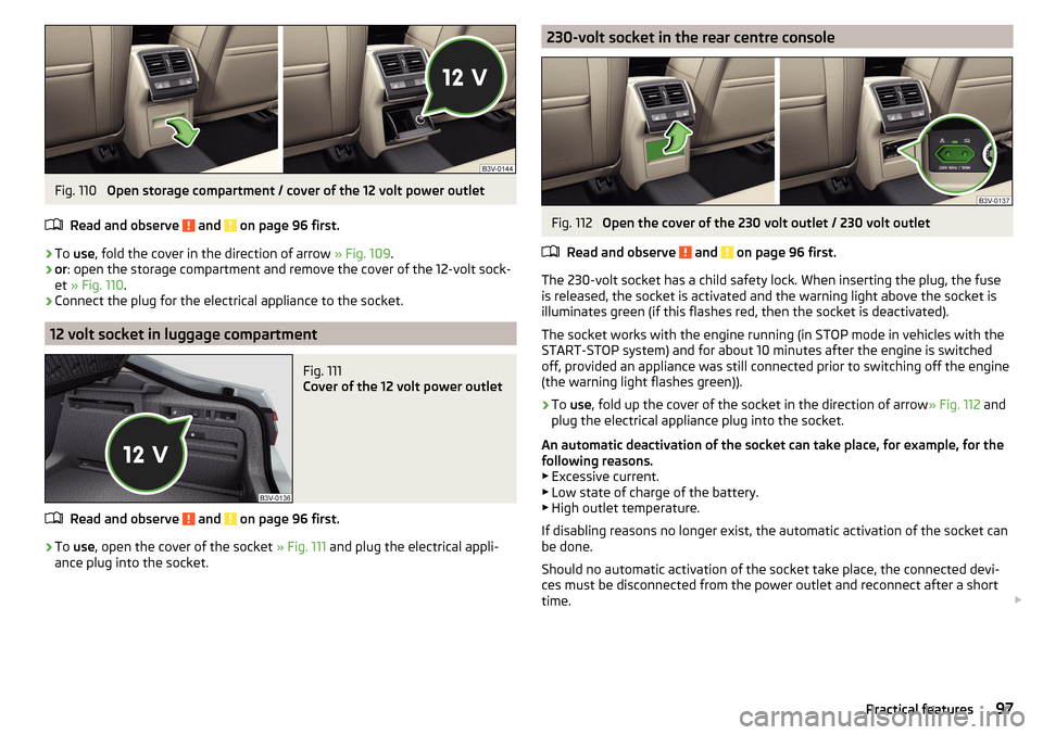
Fig. 110
Open storage compartment / cover of the 12 volt power outlet
Read and observe
and on page 96 first.
›
To use , fold the cover in the direction of arrow » Fig. 109.
›
or: open the storage compartment and remove the cover of the 12-volt sock-
et » Fig. 110 .
›
Connect the plug for the electrical appliance to the socket.
12 volt socket in luggage compartment
Fig. 111
Cover of the 12 volt power outlet
Read and observe and on page 96 first.
›
To use , open the cover of the socket » Fig. 111 and plug the electrical appli-
ance plug into the socket.
230-volt socket in the rear centre consoleFig. 112
Open the cover of the 230 volt outlet / 230 volt outlet
Read and observe
and on page 96 first.
The 230-volt socket has a child safety lock. When inserting the plug, the fuse
is released, the socket is activated and the warning light above the socket is
illuminates green (if this flashes red, then the socket is deactivated).
The socket works with the engine running (in STOP mode in vehicles with the
START-STOP system) and for about 10 minutes after the engine is switched
off, provided an appliance was still connected prior to switching off the engine
(the warning light flashes green)).
›
To use , fold up the cover of the socket in the direction of arrow » Fig. 112 and
plug the electrical appliance plug into the socket.
An automatic deactivation of the socket can take place, for example, for the
following reasons. ▶ Excessive current.
▶ Low state of charge of the battery.
▶ High outlet temperature.
If disabling reasons no longer exist, the automatic activation of the socket can
be done.
Should no automatic activation of the socket take place, the connected devi-
ces must be disconnected from the power outlet and reconnect after a short
time.
97Practical features
Page 297 of 336
Replacing the rear window wiper bladeFig. 355
Replace the rear window wiper blade
Read and observe
on page 294 first.
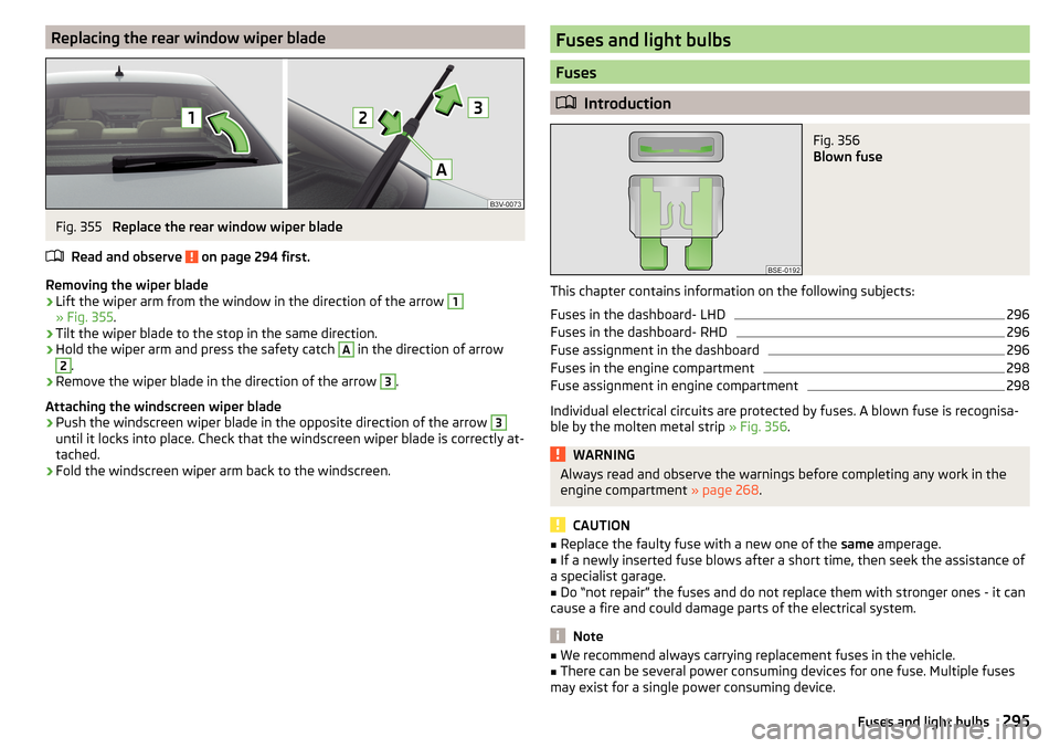
Removing the wiper blade
›
Lift the wiper arm from the window in the direction of the arrow
1
» Fig. 355 .
›
Tilt the wiper blade to the stop in the same direction.
›
Hold the wiper arm and press the safety catch
A
in the direction of arrow
2
.
›
Remove the wiper blade in the direction of the arrow
3
.
Attaching the windscreen wiper blade
›
Push the windscreen wiper blade in the opposite direction of the arrow
3
until it locks into place. Check that the windscreen wiper blade is correctly at-
tached.
›
Fold the windscreen wiper arm back to the windscreen.
Fuses and light bulbs
Fuses
Introduction
Fig. 356
Blown fuse
This chapter contains information on the following subjects:
Fuses in the dashboard- LHD
296
Fuses in the dashboard- RHD
296
Fuse assignment in the dashboard
296
Fuses in the engine compartment
298
Fuse assignment in engine compartment
298
Individual electrical circuits are protected by fuses. A blown fuse is recognisa-
ble by the molten metal strip » Fig. 356.
WARNINGAlways read and observe the warnings before completing any work in the
engine compartment » page 268.
CAUTION
■
Replace the faulty fuse with a new one of the same amperage.■If a newly inserted fuse blows after a short time, then seek the assistance of
a specialist garage.■
Do “not repair” the fuses and do not replace them with stronger ones - it can
cause a fire and could damage parts of the electrical system.
Note
■ We recommend always carrying replacement fuses in the vehicle.■There can be several power consuming devices for one fuse. Multiple fuses
may exist for a single power consuming device.295Fuses and light bulbs
Page 298 of 336
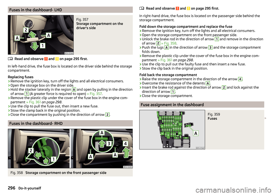
Fuses in the dashboard- LHDFig. 357
Storage compartment on the
driver's side
Read and observe and on page 295 first.
In left-hand drive, the fuse box is located on the driver side behind the storage compartment.
Replacing fuses
›
Remove the ignition key, turn off the lights and all electrical consumers.
›
Open the storage box on the driver side.
›
Hold the stacker laterally in the region
A
and open by pulling in the direction
of arrow
1
(A greater force is required to open) » Fig. 357.
›
Remove the plastic clip under the cover of the fuse box in the engine com-
partment » Fig. 361 on page 298 .
›
Use the clip to pull the fuse out, then insert a new fuse.
›
Stow the clamp back in the original position.
›
Close the compartment by pushing in the direction of arrow
2
.
Fuses in the dashboard- RHD
Fig. 358
Storage compartment on the front passenger side
Read and observe and on page 295 first.
In right-hand drive, the fuse box is located on the passenger side behind the
storage compartment.
Fold down the storage compartment and replace the fuse
›
Remove the ignition key, turn off the lights and all electrical consumers.
›
Open the storage compartment on the front passenger side.
›
Unlock the brake rod in the direction of arrow
1
and remove in the direction
of arrow
2
» Fig. 358 .
›
Push the lugs
A
in the direction of arrow
3
and the storage compartment
folds down.
›
Remove the plastic clip under the cover of the fuse box in the engine com-
partment » Fig. 361 on page 298 .
›
Use the clip to pull out the faulty fuse and then insert a new fuse.
›
Stow the clip back in the original position.
Fold back the storage compartment
›
Raise the storage compartment in the direction of the arrow
4
.
›
Overcome the resistance of the detents
A
.
›
Insert the brake rod against the direction of arrow
2
and lock against the
direction of arrow
1
.
›
Close the storage compartment.
Fuse assignment in the dashboard
Fig. 359
Fuses
296Do-it-yourself
Page 299 of 336
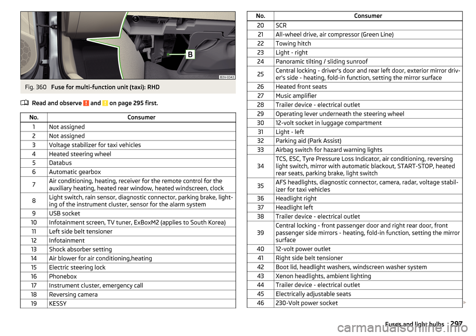
Fig. 360
Fuse for multi-function unit (taxi): RHD
Read and observe
and on page 295 first.
No.Consumer1Not assigned2Not assigned3Voltage stabilizer for taxi vehicles4Heated steering wheel5Databus6Automatic gearbox7Air conditioning, heating, receiver for the remote control for the
auxiliary heating, heated rear window, heated windscreen, clock8Light switch, rain sensor, diagnostic connector, parking brake, light-
ing of the instrument cluster, sensor for the alarm system9USB socket10Infotainment screen, TV tuner, ExBoxM2 (applies to South Korea)11Left side belt tensioner12Infotainment13Shock absorber setting14Air blower for air conditioning,heating15Electric steering lock16Phonebox17Instrument cluster, emergency call18Reversing camera19KESSYNo.Consumer20SCR21All-wheel drive, air compressor (Green Line)22Towing hitch23Light - right24Panoramic tilting / sliding sunroof25Central locking - driver's door and rear left door, exterior mirror driv-
er's side - heating, fold-in function, setting the mirror surface26Heated front seats27Music amplifier28Trailer device - electrical outlet29Operating lever underneath the steering wheel3012-volt socket in luggage compartment31Light - left32Parking aid (Park Assist)33Airbag switch for hazard warning lights34TCS, ESC, Tyre Pressure Loss Indicator, air conditioning, reversing
light switch, mirror with automatic blackout, START-STOP, heated
rear seats, parking brake, light switch35AFS headlights, diagnostic connector, camera, radar, voltage stabil-
izer for taxi vehicles36Headlight right37Headlight left38Trailer device - electrical outlet39Central locking - front passenger door and right rear door, front
passenger side mirrors - heating, fold-in function, setting the mirror
surface4012-volt power outlet41Right side belt tensioner42Boot lid, headlight washers, windscreen washer system43Xenon headlights, ambient lighting44Trailer device - electrical outlet45Electrically adjustable seats46230-Volt power socket 297Fuses and light bulbs
Page 300 of 336
No.Consumer47Rear window wiper48Blind spot detection49Engine starting, clutch pedal switch50Opening the boot lid51Heating of the rear seats52Heated front seats53Heated rear windowA
» Fig. 359Multifunctional unit for taxi vehicles - LHD
B
» Fig. 36 0Multifunctional unit for taxi vehicles - RHD
Fuses in the engine compartment
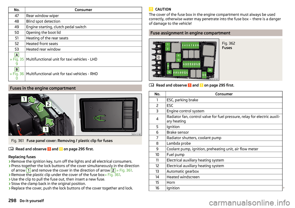
Fig. 361
Fuse panel cover: Removing / plastic clip for fuses
Read and observe
and on page 295 first.
Replacing fuses
›
Remove the ignition key, turn off the lights and all electrical consumers.
›
Press together the lock buttons of the cover simultaneously in the direction
of arrow
1
and remove the cover in the direction of arrow
2
» Fig. 361 .
›
Remove the plastic clip under the cover of the fuse box » Fig. 361.
›
Use the clip to pull the fuse out, then insert a new fuse.
›
Stow the clamp back in the original position.
›
Replace the cover, push the lock buttons of the cover together and lock.
CAUTIONThe cover of the fuse box in the engine compartment must always be used
correctly, otherwise water may penetrate into the fuse box – there is a danger
of damage to the vehicle!
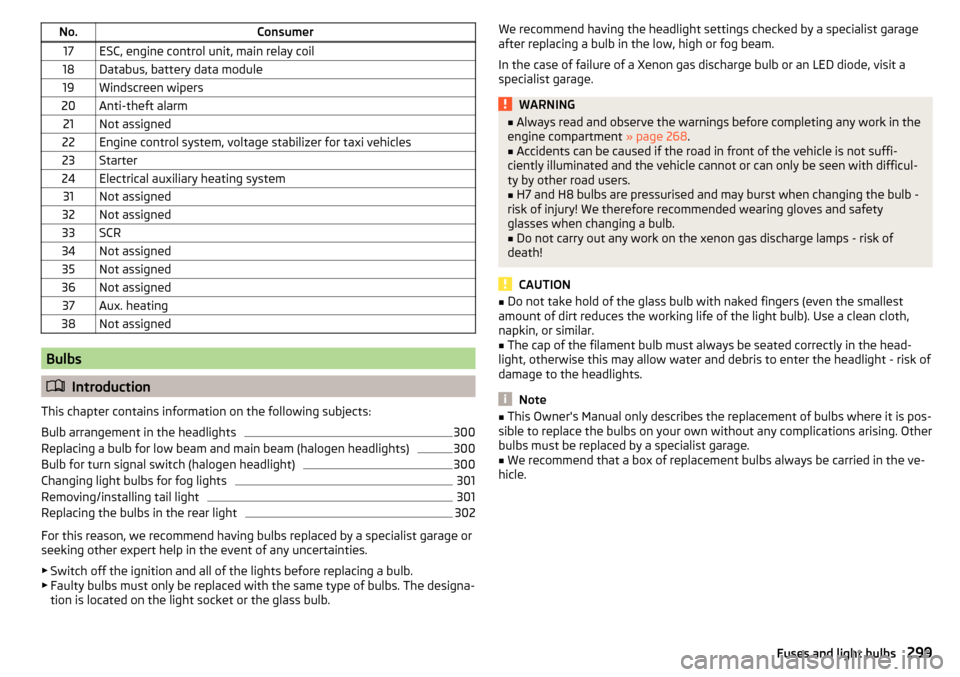
Fuse assignment in engine compartment
Fig. 362
Fuses
Read and observe and on page 295 first.
No.Consumer1ESC, parking brake2ESC3Engine control system4Radiator fan, control valve for fuel pressure, relay for electric auxili-
ary heating5Ignition6Brake sensor7Radiator shutters, coolant pump8Lambda probe9Coolant pump, ignition, preheating unit, air flow meter10Fuel pump11Electrical auxiliary heating system12Electrical auxiliary heating system13Automatic gearbox14Heated windscreen15Horn16Ignition 298Do-it-yourself
Page 301 of 336
No.Consumer17ESC, engine control unit, main relay coil18Databus, battery data module19Windscreen wipers20Anti-theft alarm21Not assigned22Engine control system, voltage stabilizer for taxi vehicles23Starter24Electrical auxiliary heating system31Not assigned32Not assigned33SCR34Not assigned35Not assigned36Not assigned37Aux. heating38Not assigned
Bulbs
Introduction
This chapter contains information on the following subjects:
Bulb arrangement in the headlights
300
Replacing a bulb for low beam and main beam (halogen headlights)
300
Bulb for turn signal switch (halogen headlight)
300
Changing light bulbs for fog lights
301
Removing/installing tail light
301
Replacing the bulbs in the rear light
302
For this reason, we recommend having bulbs replaced by a specialist garage or
seeking other expert help in the event of any uncertainties.
▶ Switch off the ignition and all of the lights before replacing a bulb.
▶ Faulty bulbs must only be replaced with the same type of bulbs. The designa-
tion is located on the light socket or the glass bulb.
We recommend having the headlight settings checked by a specialist garage
after replacing a bulb in the low, high or fog beam.
In the case of failure of a Xenon gas discharge bulb or an LED diode, visit a
specialist garage.WARNING■ Always read and observe the warnings before completing any work in the
engine compartment » page 268.■
Accidents can be caused if the road in front of the vehicle is not suffi-
ciently illuminated and the vehicle cannot or can only be seen with difficul-
ty by other road users.
■
H7 and H8 bulbs are pressurised and may burst when changing the bulb -
risk of injury! We therefore recommended wearing gloves and safety
glasses when changing a bulb.
■
Do not carry out any work on the xenon gas discharge lamps - risk of
death!
CAUTION
■ Do not take hold of the glass bulb with naked fingers (even the smallest
amount of dirt reduces the working life of the light bulb). Use a clean cloth,
napkin, or similar.■
The cap of the filament bulb must always be seated correctly in the head-
light, otherwise this may allow water and debris to enter the headlight - risk of
damage to the headlights.
Note
■ This Owner's Manual only describes the replacement of bulbs where it is pos-
sible to replace the bulbs on your own without any complications arising. Other
bulbs must be replaced by a specialist garage.■
We recommend that a box of replacement bulbs always be carried in the ve-
hicle.
299Fuses and light bulbs
Page 303 of 336
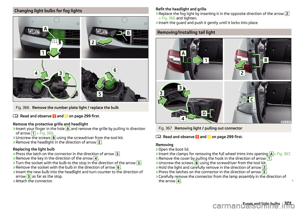
Changing light bulbs for fog lightsFig. 366
Remove the number plate light / replace the bulb
Read and observe
and on page 299 first.
Remove the protective grille and headlight
›
Insert your finger in the hole
A
and remove the grille by pulling in direction
of arrow
1
» Fig. 366 .
›
Unscrew the screws
B
using the screwdriver from the tool kit.
›
Remove the headlight in the direction of arrow
2
.
Replacing the light bulb
›
Press the latch on the connector in the direction of arrow
3
.
›
Remove the key in the direction of the arrow
4
.
›
Turn the socket with the bulb to the stop in the direction of the arrow
5
.
›
Remove the socket with the bulb in the direction of arrow
6
.
›
Insert the new bulb into the headlight and turn counter to the direction of
arrow
5
as far as the stop.
›
Attach the connector.
Refit the headlight and grille›Replace the fog light by inserting it in the opposite direction of the arrow 2
» Fig. 366 and tighten.
›
Insert the guard and push it gently until it locks into place.
Removing/installing tail light
Fig. 367
Removing light / pulling out connector
Read and observe
and on page 299 first.
Removing
›
Open the boot lid.
›
Insert the clamps for removing the full wheel trims into opening
A
» Fig. 367 .
›
Remove the cover by pulling the hook in the direction of arrow
1
.
›
Unscrew the screws
B
using the screwdriver from the tool kit.
›
Hold the light and carefully remove in the direction of arrow
2
.
›
Press the latches on the connector in the direction of arrow
3
.
›
Carefully remove the connector from the lamp assembly in the direction of
the arrow
4
.
301Fuses and light bulbs
Page 319 of 336
Engine oil270
Check271
Oil changing270
Refilling271
specification270
Warning light40
Engine revolutions counter32
Enter destination address
183
Destination on the map184
Environment monitoring system Settings in Infotainment
238
EPC37
EPG TV tuner
157
Equaliser131
ESC ESC Sport
213
Operation213
Warning light36
External device data transfer132
External module CD / DVD
149
SD card150
SIM card166
Video DVD155
F
Factory settings
140
Fastening elements101
Fatigue detection248
Favourite185, 190
File formats Media
152, 153
Pictures154
Requirements and Restrictions152, 153
Video DVD156
Finish route guidance192
Fire extinguisher281
First aid kit280
Flagged destination185
Flashing68
Floor covering in the luggage compartment103
Flooring in the luggage compartment103
Floor mats206
See Floor mats206
FM142, 143
Set134, 141
Fog lights Warning light
38
Fog lights/rear fog light69
Fog lights with CORNER function70
Foils261
Force limiter Electric boot lid
59
Sliding/tilting sunroof64
Tilting / sliding sunroof64
Window63
Front Assist237
Deactivation/activation239
Distance warning238
Malfunctions240
Operation238
Radar sensor212
Settings in Infotainment238
Warning and automatic braking238
Warning light42
Front seats80
Fuel264
Diesel266
Fuel gauge33
refer to Fuel264
Refuelling265
Unleaded petrol265
Warning light38
Fuel consumption305
Fuel filter Information messages
42
Fuel reserve38
Functional surfaces125
Fuses295
in the dashboard296
in the engine compartment298
Plastic clip298
G
Gearbox Information messages
39
Gear change Gear recommendation
44
Information on the selected gear44
Gear changing lever
206
Genuine parts257
Glasses compartment92
GPS180
Graphical driving recommendations191
H
Hazard warning light system
70
HBA214
Headlight assistant71
Warning light41
Headrests84
Heating113, 114
Air distribution control117
Mirrors78
Seats85
Steering wheel86
Windscreen and rear window74
HHC214
Hill Start Assist (HHC)214
hitch252
Hitch250
Home address137, 185
Hook103
Horn31
317Index