gearbox SKODA YETI 2012 1.G / 5L Owner's Guide
[x] Cancel search | Manufacturer: SKODA, Model Year: 2012, Model line: YETI, Model: SKODA YETI 2012 1.G / 5LPages: 225, PDF Size: 5.47 MB
Page 157 of 225

Manual gearbox
› If you are driving through difficult terrain,
on no account use the clutch or
change the gear. When the clutch is depressed, the vehicle may come to a
standstill because of the increased grip of all the tyres of the vehicle (e.g. in the
mud, in deep sand or on a slope). Once the vehicle has come to a standstill, it
may be difficult or even impossible to start off under these conditions.
› When negotiating a steep downhill section or a steep uphill section, always
shift into the 1st or 2nd gear.
› On a soft or slippery ground, you must drive at the appropriate speed and you
must select the highest possible gear for this.
Automatic gearbox
› Select the selector lever position D
for normal flat stretches of ter-
rain » page 110, Selector lever positions.
› While in Tiptronic mode, select the selector lever position 3
or 2
if you are
driving through mud, sand, water or hilly sections of terrain » page 111, Manual
shifting of gears (Tiptronic) .
› When negotiating a steep downhill section or a steep uphill section, select the
selector lever position 1
while in Tiptronic mode
› On a soft or slippery ground, you must drive at the appropriate speed and you
must select the highest possible driving stage for this. ÐDriving at an angle on a hillside
Fig. 137
Steer and maintain your trajec-
tory/in direction to exit - facing
uphill
First read and observe the introductory information and safety warn-
ings on page 151.
Driving at an angle on a hillside is one of the most dangerous situations while
driving off-road.
ä If the vehicle is at a very steep angle, the wheels on the low side must not sink
deeply into the ground or into troughs and you must not drive over stones, tree
stumps or other obstructions with the alternate raised wheels.
If there is a risk your vehicle may tilt, steer immediately in direction of dip A
and
lightly depress the accelerator » Fig. 137.
A passenger, seated at the rear, should always remain seated on the seat facing
up the hill during such a journey. In an extreme case, the passenger on the rele-
vant side must exit the vehicle until you have safely crossed the hillside.
Exiting the vehicle on a hillside
If the vehicle comes to a standstill at a steep angle on a hillside and you and your
passengers must exit the vehicle, then all the occupants should exit on the side
facing up the hill B
» Fig. 137
. WARNING
■ Before driving at an angle on a hillside A
» Fig. 137
, ensure that you can
steer and maintain your trajectory. If you drive at an angle on a hillside and
there is a risk your vehicle may tilt, steer immediately downhill on your trajec-
tory and lightly depress the accelerator. ■ In case the vehicle is stationary on a hillside at a steep angle, do not exit the
vehicle when it is facing downhill. Always leave the vehicle carefully on the
side facing downhill B
» Fig. 137.
■ When driving at an angle on a hillside, the vehicle can lose its grip and slide
sideways. Always make sure that the wheels on the low side do not sink
deeply into the ground or into troughs and do not drive over stones, tree
stumps or other obstructions with the alternate raised wheels - risk of acci-
dent! Ð Stuck vehicle
First read and observe the introductory information and safety warn-
ings on page 151.
If you can no longer drive on ...
›
Carefully dig out all wheels and ensure that no other parts of the vehicle are
still stuck.
› Engage reverse gear.
› Carefully press the accelerator and try to reverse in a straight line.
› Place scrub, footmats or a sackcloth directly in front of the tyres in order to im-
prove grip and thus achieve an improved traction to drive out. £
ä
155
Driving and the Environment
Page 171 of 225
Diesel fuel
First read and observe the introductory information and safety warn-
ings on page 167.
Your vehicle can only be operated with
diesel fuel, which complies with the
standard EN
590 (standard DIN 51628 in Germany, standard ÖNORM C 1590 in
Austria, GOST R 52368-2005/EN 590:2004 in Russia).
Operation in winter - Winter-grade diesel fuel
In the winter, only use diesel fuel, which complies with the standard EN 590
(standard DIN 51628 in Germany, standard ÖNORM C 1590 in Austria,
GOST R 52368-2005/EN 590:2004 in Russia). “Winter-grade diesel fuel” will still
operate properly even at a temperature of -20 °C.
It is often the case in countries with different climatic conditions that diesel fuels
available have a different temperature characteristic. The ŠKODA Service Partners
and filling stations in the relevant country will be able to provide you with infor-
mation regarding the diesel fuels available.
Preheating fuel
The vehicle is fitted with a fuel filter preheating system. This secures operation of
a vehicle using diesel fuel down to an environmental temperature of -25 °C.
Fuel additives
Fuel additives, so-called “flow improvers” (petrol and similar products) must not
be added to the diesel fuel. CAUTION
■ Just filling the tank once with diesel fuel that does not comply with the stand-
ard, can cause severe damage to parts of the engine, the fuel and exhaust sys-
tem!
■ If a different fuel other than diesel fuel, which complies to the above mentioned
standards (e.g. petrol) is used by mistake do not start the engine or switch on the
ignition! Extensive damage to engine parts can occur! We recommend that the
fuel system is cleaned by a
ŠKODA Service Partner.
■ Water which has collected in the fuel filter can cause engine faults.
■ Your vehicle is not adapted for use of biofuel (RME), therefore this fuel must not
be refuelled and driven. The use of biofuel (RME) can cause considerable damage
to parts of the engine or fuel system. Ð
ä Engine compartment
ä
Introduction
This chapter contains information on the following subjects:
Opening and closing the bonnet 171
Engine compartment overview 171
Checking the engine oil level 172
Replenishing the engine oil 172
Changing engine oil 173
Coolant 173
Checking the coolant level 174
Replenishing the coolant 174
Radiator fan 175
Checking the brake fluid 175
Changing the brake fluid 175
Windscreen washer system 176
There is a risk of injuries, scalding, accidents and fire when working in the en-
gine compartment, e.g. inspecting and replenishing oil and other fluids. For this
reason, it is essential to comply with the warning instructions stated below and
with the general applicable rules of safety. The vehicle's engine compartment is
a hazardous area . WARNING
■ Never open the bonnet if you can see steam or coolant flowing out of the
engine compartment - risk of scalding! Wait until the steam or coolant has
stopped escaping.
■ Turn off the engine and withdraw the ignition key.
■ If the vehicle is fitted with a manual gearbox, move the gearshift lever into
Neutral, or if the vehicle is fitted with an automatic gearbox, move the selec-
tor lever into position P .
■ Firmly apply the handbrake.
■ Allow the engine to cool.
■ For safety reasons, the bonnet must always be properly closed when driving.
This is why after closing the bonnet, the lock must always be checked to en-
sure it has engaged properly. £
169
Inspecting and replenishing
Page 194 of 225
Preliminary work
First read and observe the introductory information and safety warn-
ings on page 191.
The following steps must be carried out before actually changing the wheel:
›
In the event of a puncture, park the vehicle as far away as possible from the
flow of traffic. The place you choose should be level.
› Let all of the occupants get out.
While changing a tyre, the occupants of the
vehicle should not stand on the road (instead they should remain behind a crash
barrier).
› Switch off the engine and move the gearshift lever into
Neutral or move the
selector lever for the automatic gearbox into position P .
› Firmly apply the
handbrake.
› If a trailer is connected, remove it.
› Remove the vehicle tool kit
» page 190 and the spare wheel » page 184 from
the boot. ÐChanging a wheel
First read and observe the introductory information and safety warn-
ings on page 191.
Always change a wheel on a level surface as far as possible.
›
Remove the full wheel trim
» page 185 or caps » page 185 .
› In the case of light alloy wheel rims remove the wheel trim cap
» page 185.
› First of all slacken the anti-theft wheel bolt and then the other wheel
bolts » page 194.
› Jack up the vehicle until the wheel that needs changing is clear of the
ground » page 193.
› Unscrew the wheel bolts and place them on a clean surface (cloth, paper, etc.).
› Remove the wheel.
› Attach the spare wheel and slightly screw on the wheel bolts.
› Lower the vehicle.
› Alternately tighten the wheel bolts opposite each other using the wheel
wrench (crosswise) and then tighten the anti-theft wheel bolt » page 194.
› Reinstall the wheel trim/wheel trim cap or the caps.
ä
ä Note
■ All bolts must be clean and must turn easily.
■ Under no circumstances grease or oil the wheel bolts!
■ When fitting unidirectional tyres, ensure that the direction of rotation is cor-
rect »
page 181 . Ð Subsequent steps
First read and observe the introductory information and safety warn-
ings on page 191.
The following steps must also be performed after changing the wheel.
›
Stow and attach the replaced wheel in the spare wheel well using a special
screw » page 184 .
› Stow the vehicle tool kit in the space provided.
› Check
the tyre pressure
on the installed spare wheel as soon as possible.
› Have the
tightening torque of the wheel bolts checked with a torque wrench
as soon as possible.
› Change the damaged wheel or consult a ŠKODA specialist garage about repair
possibilities. Note
■ If it is determined that the wheel bolts are corroded and difficult to turn when
changing the wheel, the bolts must be replaced before checking the tightening
torque. ■ Drive cautiously and only at a moderate speed until the tightening torque has
been checked. Ð
ä
192 Do-it-yourself
Page 197 of 225

WARNING (Continued)
■ Do not drive faster than 80 km/h (50 mph).
■ Avoid accelerating at full throttle, sharp braking and fast cornering.
■ Check the tyre inflation pressure after driving for 10 minutes!
■ The sealant is hazardous to heath. Remove immediately if it comes into con-
tact with the skin. For the sake of the environment
Used sealant or sealant whose expiry date has passed must be disposed of in ac-
cordance with environmental protection regulations. Note
■ Observe the manufacturer's usage instructions for the breakdown kit.
■ A new bottle of sealant can be purchased from ŠKODA Original Accessories.
■ Immediately replace the wheel that was repaired using the breakdown kit or
consult a ŠKODA specialist garage about repair possibilities. ÐComponents of the breakdown kit
Fig. 160
Components of the breakdown kit
First read and observe the introductory information and safety warn-
ings on page 194.
ä The breakdown kit contains the following parts:
Valve remover
Sticker with speed designation
“max. 80 km/h”/“max. 50 mph”
Inflation hose with plug
Air compressor
Tyre inflation hose
Tyre inflation pressure indicator
Air release valve
ON and OFF switch
12 volt cable connector
Tyre inflator bottle with sealing agent
Replacement valve core
The valve remover 1
has a slot at its lower end which fits into the valve core.
This is the only way in which you can remove and re-install the valve core from
the tyre valve. The same also applies to the replacement valve core 11
.
Ð Preparing to use the breakdown kit
First read and observe the introductory information and safety warn-
ings on page 194.
The following preparatory work must be carried out before using the breakdown
kit.
›
In the event of a puncture, park the vehicle as far away as possible from the
flow of traffic. Park on as flat and firm a surface as possible.
› Let all of the occupants get out.
While changing a tyre, the occupants of the
vehicle should not stand on the road (instead they should remain behind a crash
barrier).
› Switch off the engine and move the gearshift lever into
Neutral or move the
selector lever
for the automatic gearbox into position P .
› Firmly apply the
handbrake.
› Check that you can carry out the repairs with the breakdown kit
» page 194.
› If a trailer is connected, remove it.
› Remove the breakdown kit
from the boot.
› Stick the sticker 2
»
Fig. 160
on page 195 on the dash panel in view of the driv-
er.
› Do not remove the foreign body, e.g. screw or nail, from the tyre.
› Unscrew the valve cap.
£ 1
2
3
4
5
6
7
8
9
10
11
ä
195
Do-it-yourself
Page 200 of 225
›
Attach the other end 4
to a solid metal part which is connected firmly to the
engine block, or to the engine block itself.
Starting engine
› Start the engine on the vehicle providing the power and allow it to idle.
› Now start the engine of the vehicle with the discharged battery.
› If the engine does not start, terminate the attempt to start the engine after
10 seconds and wait for about 30 seconds before repeating the process.
› Disconnect the cables in exactly the
reverse order to the one described above. ÐJump-starting in vehicles with the START-STOP system
Fig. 162
Jump-starting - START-STOP
system
First read and observe the introductory information and safety warn-
ings on page 197.
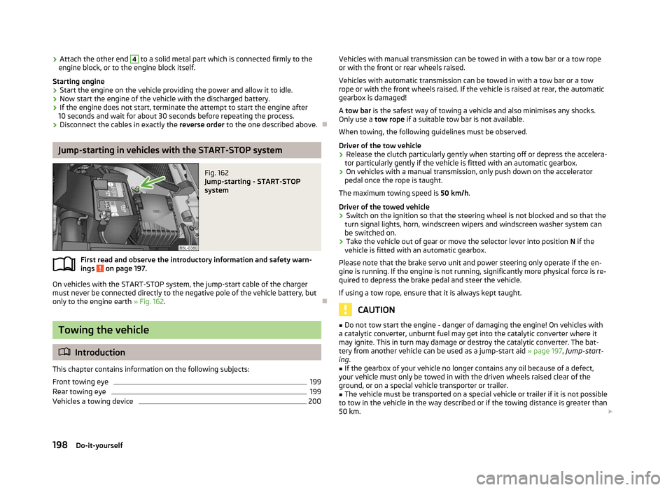
On vehicles with the START-STOP system, the jump-start cable of the charger
must never be connected directly to the negative pole of the vehicle battery, but
only to the engine earth » Fig. 162. ÐTowing the vehicle
ä
Introduction
This chapter contains information on the following subjects:
Front towing eye 199
Rear towing eye 199
Vehicles a towing device 200
ä Vehicles with manual transmission can be towed in with a tow bar or a tow rope
or with the front or rear wheels raised.
Vehicles with automatic transmission can be towed in with a tow bar or a tow
rope or with the front wheels raised. If the vehicle is raised at rear, the automatic
gearbox is damaged!
A tow bar is the safest way of towing a vehicle and also minimises any shocks.
Only use a tow rope if a suitable tow bar is not available.
When towing, the following guidelines must be observed.
Driver of the tow vehicle › Release the clutch particularly gently when starting off or depress the accelera-
tor particularly gently if the vehicle is fitted with an automatic gearbox.
› On vehicles with a manual transmission, only push down on the accelerator
pedal once the rope is taught.
The maximum towing speed is 50 km/h.
Driver of the towed vehicle
› Switch on the ignition so that the steering wheel is not blocked and so that the
turn signal lights, horn, windscreen wipers and windscreen washer system can
be switched on.
› Take the vehicle out of gear or move the selector lever into position
N if the
vehicle is fitted with an automatic gearbox.
Please note that the brake servo unit and power steering only operate if the en-
gine is running. If the engine is not running, significantly more physical force is re-
quired to depress the brake pedal and steer the vehicle.
If using a tow rope, ensure that it is always kept taught. CAUTION
■ Do not tow start the engine - danger of damaging the engine! On vehicles with
a catalytic converter, unburnt fuel may get into the catalytic converter where it
may ignite. This in turn may damage or destroy the catalytic converter. The bat-
tery from another vehicle can be used as a jump-start aid » page 197, Jump-start-
ing .
■ If the gearbox of your vehicle no longer contains any oil because of a defect,
your vehicle must only be towed in with the driven wheels raised clear of the
ground, or on a special vehicle transporter or trailer.
■ The vehicle must be transported on a special vehicle or trailer if it is not possible
to tow in the vehicle in the way described or if the towing distance is greater than
50 km. £
198 Do-it-yourself
Page 204 of 225
Fuses in the dash panel
Fig. 165
Fuse box cover in the dash panel/schematic diagram of the fuse
box
First read and observe the introductory information and safety warn-
ings on page 201.
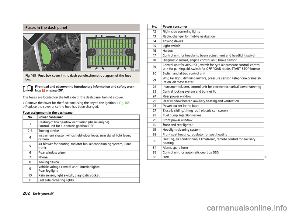
The fuses are located on the left side of the dash panel behind a cover.
›
Remove the cover for the fuse box using the key to the ignition
» Fig. 165.
› Replace the cover once the fuse has been changed.
Fuse assignment in the dash panel No. Power consumer
1 Heating of the gearbox ventilation (diesel engine)
Control unit for automatic gearbox DSG
2-3 Towing device
4 Instrument cluster, windshield wiper lever, turn signal light lever,
camera
5 Air blower for heating, radiator fan, air conditioning system, Clima-
tronic
6 Rear window wiper 7 Phone
8 Towing device
9 Vehicle voltage control unit - interior lights
Rear fog light
10 Rain sensor, light switch, diagnostic socket 11 Left side cornering lights ä
No. Power consumer
12 Right side cornering lights
13 Radio, changer for mobile navigation
14 Towing device 15 Light switch
16 Haldex 17 Control unit for headlamp beam adjustment and headlight swivel
18 Diagnostic socket, engine control unit, brake sensor
19 Control unit for ABS, ESP, switch for tyre air pressure control, control
unit for parking aid, switch for
OFF ROAD mode, START STOP button
20 Switch and airbag control unit
21 WIV, tail light, dimming mirrors, pressure sensor, telephone preinstal-
lation, air mass meter
22 Instrument cluster, control unit for electromechanical power steering
23 Central locking system and bonnet lid
24 Rear power window 25 Rear window heater, auxiliary heating and ventilation
26 Power socket in the boot 27 Electric sliding/tilting roof, electric sun screen
28 Fuel pump, injection valves 29 Front power window
30 front and rear lighter 31 Headlight cleaning system
32 Front seat heating, regulator for seat heating
33 Heating, air conditioning, Climatronic, remote control for auxiliary
heating
34 Alarm, spare horn 35 Control unit for automatic gearbox DSG
36 DVD Ð
202 Do-it-yourself
Page 205 of 225
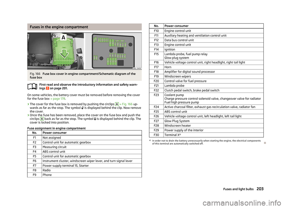
Fuses in the engine compartment
Fig. 166
Fuse box cover in engine compartment/Schematic diagram of the
fuse box
First read and observe the introductory information and safety warn-
ings on page 201.
On some vehicles, the battery cover must be removed before removing the cover
for the fuse box
» page 178.
› The cover for the fuse box is removed by pushing the circlips A
» Fig. 166
up-
wards as far as the stop. The symbol is displayed behind the clip. Now remove
the cover.
› Once the fuse has been removed, place the cover on the fuse box and push the
circlips A
back as far as the stop. The symbol
is displayed behind the clip. The
cover is locked into position.
Fuse assignment in engine compartment No. Power consumer
F1 Not assigned
F2 Control unit for automatic gearbox
F3 Measuring circuit
F4 ABS control unit F5 Control unit for automatic gearbox
F6 Instrument cluster, windscreen wiper lever, and turn signal lever F7 Power supply terminal 15, Starter
F8 Radio F9 Phone ä
No. Power consumer
F10 Engine control unit F11 Auxiliary heating and ventilation control unit
F12 Data bus control unit
F13 Engine control unit
F14 Ignition F15 Lambda probe, fuel pump relay Glow plug system
F16 Vehicle voltage control unit, right headlight, right tail light F17 Horn
F18 Amplifier for digital sound processor F19 Windscreen wipers
F20 Control valve for fuel pressure F21 Lambda probe
F22 Clutch pedal switch, brake pedal switch
F23 Coolant pump Charge pressure control solenoid valve, changeover valve for radiator
Fuel high pressure pump
F24 Active charcoal filter, exhaust gas recirculation valve, radiator fan F25 ABS control unit
F26 Vehicle voltage control unit, left headlight, left tail light F27 Glow Plug System
F28 Windscreen heater F29 Power supply of the interior
F30 Terminal X a) a)
In order not to drain the battery unnecessarily when starting the engine, the electrical components
of this terminal are automatically switched off. Ð
203
Fuses and light bulbs
Page 210 of 225

Technical data
Technical data
Introductory information
The details given in the vehicle's technical documentation always take prece-
dence over the details in the Owner's Manual. Please refer to the official vehicle
registration documents or consult a
ŠKODA Service Partner to determine which
engine your vehicle is equipped with.
The listed performance values were determined without performance-reducing
equipment, e.g. air conditioning system.
Vehicle identification number (VIN)
The vehicle identification number - VIN (vehicle body number) is stamped into the
engine compartment on the right hand suspension strut dome. This number is al-
so located on a sign on the lower left hand edge below the windscreen (together
with a VIN bar code).
Engine number
The engine number is stamped into the engine block. ÐData on the vehicle data sticker and the type plate
Fig. 174
Vehicle data sticker/type plate Vehicle data sticker
The vehicle data sticker
» Fig. 174 is located on the floor of the boot and is also
stated in the service schedule.
The vehicle data sticker contains the following data:
Vehicle identification number (VIN)
Vehicle type
Gearbox code/paint number/interior equipment/engine output/engine code
Partial description of the vehicle
Operating weight (in kg)
Fuel consumption (in ltr./100
km) - intra-urban/extra-urban/combined
CO 2 emission levels - combined (in g/km)
Type plate
The type plate » Fig. 174 is located on the lower part of the column between the
front and rear doors on the front passenger's side.
The type plate lists the following weights: Maximum permissible gross weight
Maximum permissible towed weight (towing vehicle and trailer)
Maximum permissible front axle load
Maximum permissible rear axle load
Operating weight
The specified operating weight is for orientation purposes only. This value repre-
sents the minimum operating weight without additional weight-increasing equip-
ment such as air conditioning system, spare wheel, or trailer hitch.
The operating weight also contains the weight of the driver (75 kg), the weight of
the operating fluids, the tool kit, and a fuel tank filled to 90 % capacity.
It is possible to calculate the approximate loading capacity from the difference
between the permissible total weight and the operating weight » .
The payload consists of the following components:
› Passengers
› All items of luggage and other loads
› Roof load including roof rack system
› Equipment not included in the operating weight
› Trailer drawbar load when towing a trailer (max. 80 kg).
£ 1
2
3
4
5
6
7
8
9
10
11
208
Technical data
Page 216 of 225

2.0 ltr./125 kW TDI CR engine
Output (kW per rpm) Max. torque (Nm at rpm)Number of cylinders/Displacement (cm3
)
125/4200 350/1750-2500 4/1968Performances
MG6 4x4
Top speed (km/h) 201
Acceleration 0 - 100 km/h (s) 8.4
Permissible trailer load, braked (kg) 2000
Permissible trailer load, unbraked (kg) 750 Ð
Multi-purpose vehicles (AF)
Engine 1.2 ltr./77 kW TSI 1.4 ltr./90 kW TSI 1.8 ltr./118 (112) kW
TSI1.6 ltr./77 kW TDI
CR2.0 ltr./81 kW TDI
CR 2.0 ltr./103 kW TDI
CR2.0 ltr./125 kW TDI
CR
Maximum permissi-
ble gross weight
(kg) 1880/1910
a)
1915/1935b)
2045/2080 c)
1950 1955/2065d)
2070/2095 a)
(2010) b)
2075a)
Valid for vehicles with automatic gearbox.
b) Applies to vehicles with a Green-tec package.
c) 1.8 ltr./112 kW TSI.
d) Valid for 4x4 vehicles. Ð
214 Technical data
Page 217 of 225
Index
A
Ability to climb see Slope angle 153
ABS Function 97
Warning light 22
Accessories 189
Active driver-steering recommendation (DSR) 96
Adjusting Exterior mirror 53
Adjusting seats 129
Adjustment Seat 56
Aerial 161
see Radio reception 163
Airbag 137
Deployment 137
Front airbag 138
Head airbag 141
Knee airbag 139
Side airbag 140
Airbag system 137
Air conditioning system Air outlet vents 81
Climatronic 86
Manual air conditioning system 83
Alarm 31
Anti-theft alarm system 31
Antilock brake system 97
Armrest 75
Ashtray 70
Assistance systems OFF ROAD 98
Assist systems ABS 22, 97
Cruise control systems (CCS) 104EDL 98
ESC 22, 96
Park assist 101
Parking aid 100
START/STOP 106
TCS 22, 97
Auto Check Control 17
Automatic driving lamp control 40
Automatic gearbox 109
Dynamic shift programme 112
Emergency programme 112
Information for driving 109
Kickdown 112
Manual shifting of gears 111
Parking 110
Selector lever-emergency unlocking 113
Selector lever lock 111
Selector lever positions 110
Starting off 110
Stopping 110
Tiptronic 111
Automatic load deactivation 180
Auxiliary heating (auxiliary heating and ventila- tion) 88
Avoiding damage to your vehicle 150
B
Before setting off 128
Belts 132
Belt tensioners 135
Bonnet Closing 171
Opening 171
Boot Class
N1 vehicles 63
Cover 65
Emergency unlocking 34
Fastening elements 64
Fixing nets 65
Folding hooks 64Light 47
see Boot lid 33
Unlocking the boot lid 34
Variable loading floor 66
Boot lid 33
Automatic locking 33
Warning light 21
Brake assist 96
Brake booster 96
Brake fluid Checking 175
Brakes Brake assist systems 94
Handbrake 96
Indicator light 19
Running in 146
Braking Brake fluid 175
Breakdown kit 194
Bulbs Replacing 204
Button in the driver's door Electric power windows 34
C
Car computer see Multifunction display 12
Car jack 190
Carrier 68
Catalytic converter 146
CD changer 126
Central locking button 29
Central locking system 27
lock 29
unlock 28
Changes 189
Changing Engine oil 173
Wheel 191
215
Index